Panasonic KX-T2378JXW User manual
Other Panasonic Telephone manuals
Panasonic
Panasonic kx-ta6246 User manual

Panasonic
Panasonic KX-TGE463 User manual

Panasonic
Panasonic KX-TC1871CB User manual
Panasonic
Panasonic KX-TG9391T - Cordless Phone Base Station User manual
Panasonic
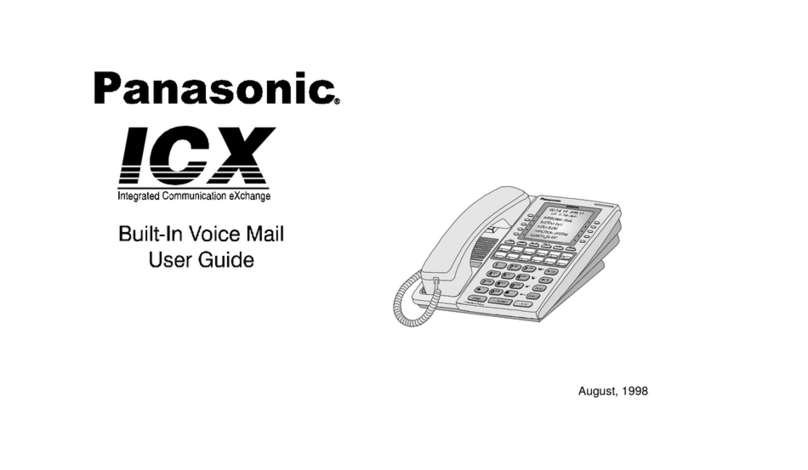
Panasonic ICX User manual
Panasonic
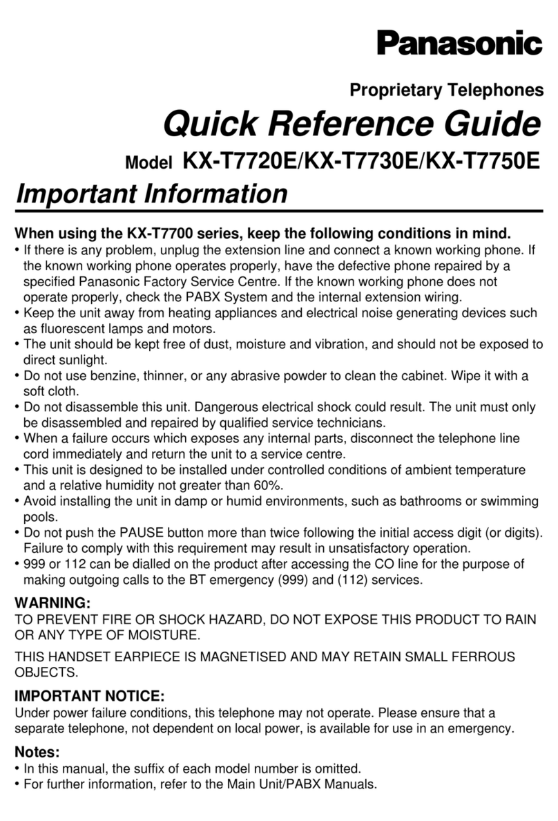
Panasonic KX-T7720E User manual
Panasonic
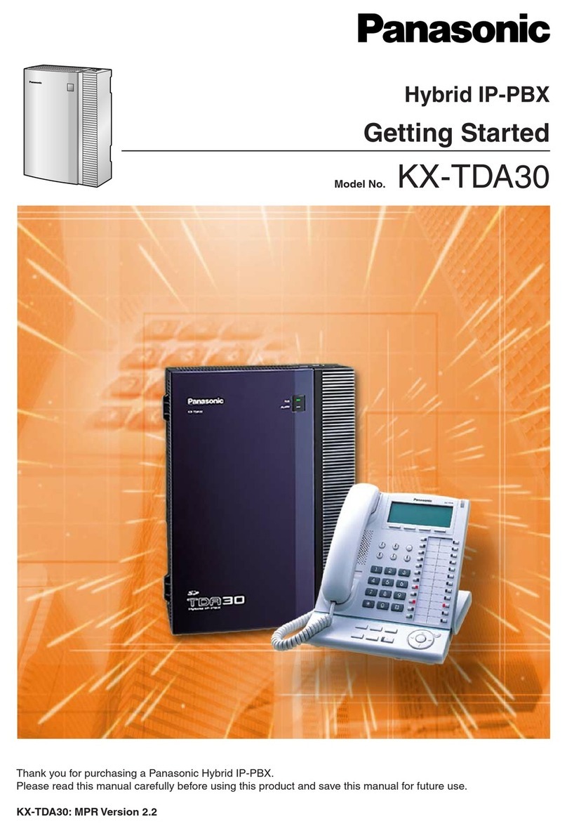
Panasonic KX-TDA30 User manual

Panasonic
Panasonic KX-TDA15 User manual
Panasonic
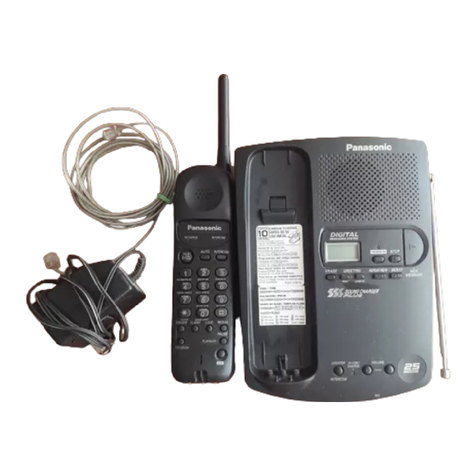
Panasonic KX-TC1040LAB User manual

Panasonic
Panasonic KX-PRW110 User manual
Panasonic
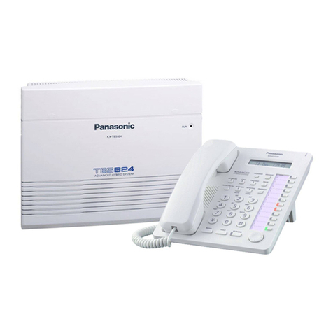
Panasonic KX-TES824 User manual

Panasonic
Panasonic KX-TCD505HKM User manual

Panasonic
Panasonic KX-HDV430 User manual
Panasonic
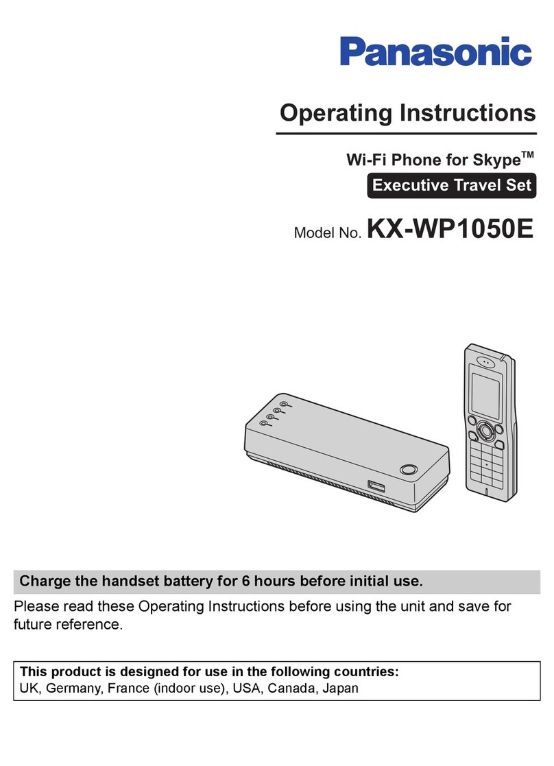
Panasonic KW-WP1050E User manual
Panasonic
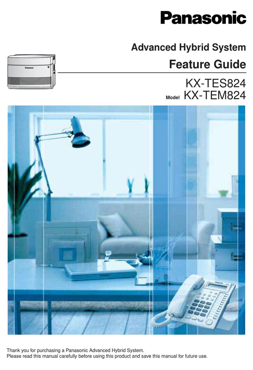
Panasonic KX-TEM824 Specification sheet

Panasonic
Panasonic KX-DT543 Reference guide

Panasonic
Panasonic KX-NCP1000 User manual
Panasonic
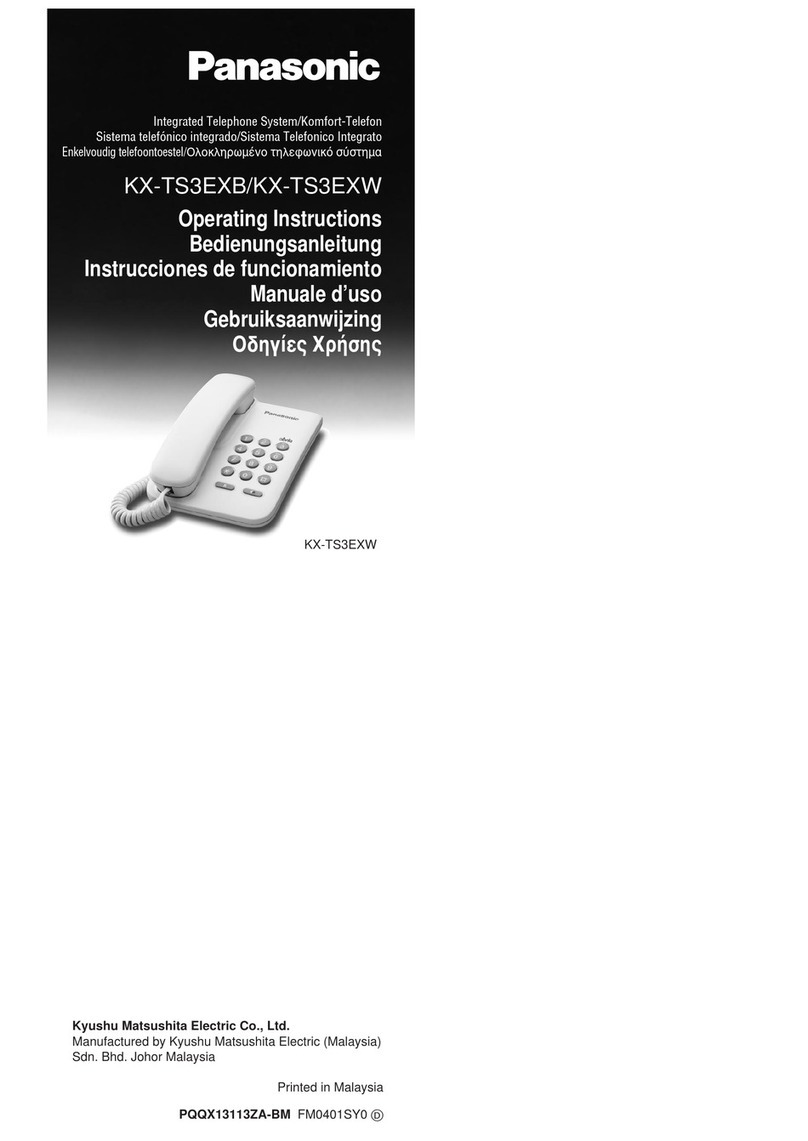
Panasonic KX-TS3EXB User manual

Panasonic
Panasonic KX-TGP600 User manual
Panasonic
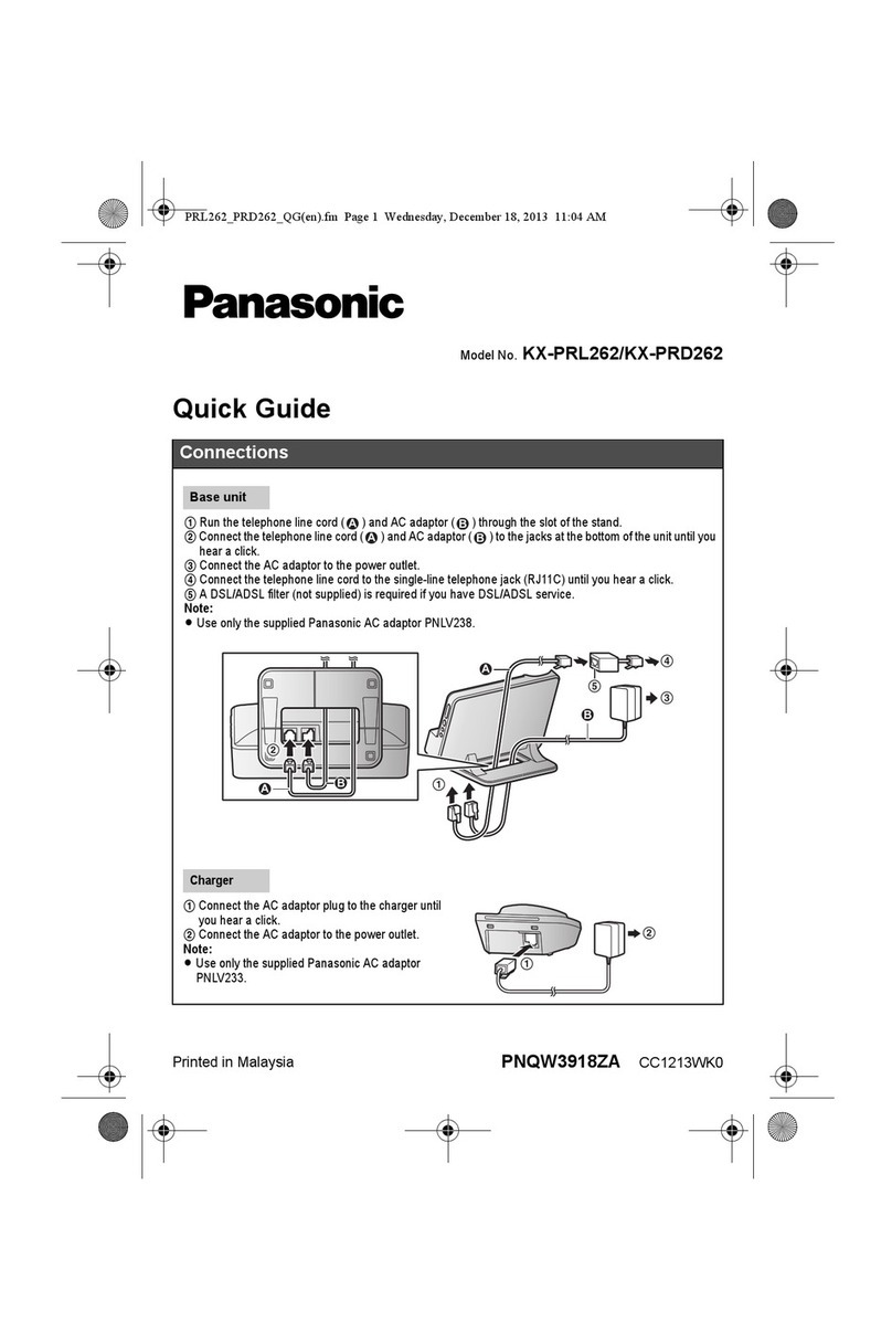
Panasonic KX-PRD262 User manual
