6
(C) Domestic Hot Water Tank Pipework
•
It’s strongly recommended to install an expansion vessel (field supply) in the
Domestic Hot Water Tank circuit. Refer Typical Piping Installation section to
locate the expansion vessel.
Recommended pre-charge pressure of the expansion vessel (field supply)
= 3.5bar (0.35MPa)
•
In high water pressure or water supply is above 5bar, please install the Pressure
Reducing Valve for water supply. If the pressure higher than that, it might
damage the Tank Unit.
•
A Pressure Reducing Valve (field supply) with below specification is strongly
advised to be installed along the line of the tube connector iof Tank Unit. Refer
Typical Piping Installation section to locate both of these valves.
Recommended Pressure Reducing Valve specifications:
-Set pressure: 3.5bar (0.35MPa)
•
Must connect a faucet to Tank Unit Tube Connector jand main water supply,
in order to supply water with appropriate temperature for shower or tap usage.
Failure to do so might cause scalding.
•
Failure to connect the tube appropriately might causing the Tank Unit malfunction.
(D) Drain Elbow and Hose Installation
•
Fix the Drain Elbow 2and Packing 3to the bottom of Drain Water Hole
h
.
Packing 3
Drain Elbow 2
•
Use inner diameter 17 mm drain hose in the market, fix to Drain Elbow 2.
•
This hose must to be installed in a continuously downward direction and in a
frost-free environment. Improper drain piping may cause water leakage hence
damage the furnitures.
•
If drain hose is long, use a metal support fixture along the way to eliminate the
wavy pattern of drain tube.
•
Guide the drain hose to outdoor as illustrated.
Discharge below
fixed grating
Fixed grating
Trapped gulley
Possible wall
Illustration of guide drain hose to outdoor
•
Do not insert this hose into sewage or drain pipe that may generate ammonia
gas, sulphuric gas etc.
•
If necessary, use hose clamp to further tighten the hose at drain hose connector
to prevent leakage.
•
Water will drip from this hose, therefore the outlet of this hose must be installed
in an area where the outlet cannot become blocked.
•
If drain hose is in the room (where dew may form), please increase the insulation
by using POLY-E FOAM with thickness 6 mm or above.
(E) Domestic Hot Water Tank Discharge (Drain Tap) and Safety Relief
Valve Pipework
•
Safety Relief Valve 8bar (0.8MPa) incorporated in Domestic Hot Water Tank.
•
Drain Tap and Safety Relief Valve discharge fittings share the same drainage outlet.
•
Use R½” male connector for this drainage outlet connection (Tube connector
g
).
•
Piping must always be installed in a continuously downward direction. It must not
be longer than 2m, with no more than 2 elbows, and must not allow condensation
to build up or freezing to occur.
•
The pipe from this drainage outlet fitting must not be shut off. The discharge
must be freed.
•
The end of this pipework must be in such a way so that the outlet is visible and can
not cause any damage. Keep away from electrical components.
•
It is recommended to fit a tundish into this
g
pipework. Tundish should be visible
and positioned away from frost environment and electrical components.
WARNING
This section is for authorized and licensed electrician only. Work
behind the Control Board Cover 5secured by screws must
only be carried out under supervision of qualified contractor,
installation engineer or service person.
CONNECT THE CABLE TO
THE TANK UNIT
4
CAUTION
Please take extra precaution when open
the control board cover 5and control
board 6for unit installation and servicing.
Failure to do so may cause injury.
Fixing of Power Supply Cable and Connecting Cable
1.
Connecting cable between Tank Unit and Outdoor Unit shall be approved
polychloroprene sheathed flexible cord, type designation 60245 IEC 57
or heavier cord. See below table for cable size requirement.
Model Connecting Cable
Size
Tank Unit Outdoor Unit
WH-ADC0509L3E5,
WH-ADC0509L3E5AN,
WH-ADC0509L6E5,
WH-ADC0509L6E5AN
WH-WDG05LE5*
WH-WDG07LE5*
WH-WDG09LE5* 4 x min 2.5 mm2
• Ensure the colour of wires of Outdoor Unit and the terminal no.
are the same to the Tank Unit respectively.
• Earth wire shall be longer than the other wires as shown in the
figure for the electrical safety in case of the slipping out of the
cord from the Holder (Clamper).
2. An isolating device must be connected to the power supply cable.
• Isolating device (disconnecting means) should have minimum
3.0 mm contact gap.
• Connect the approved polychloroprene sheathed power
supply 1 cord and power supply 2 cord and type designation
60245 IEC 57 or heavier cord to the terminal board, and to the
other end of the cord to isolating device (Disconnecting means).
See below table for cable size requirement.
Model Power
Supply
Cord
Cable Size Isolating
Devices
Recommended
RCD
Tank Unit Outdoor Unit
WH-ADC0509L3E5,
WH-ADC0509L3E5AN
WH-WDG05LE5*
WH-WDG07LE5*
WH-WDG09LE5*
1 3 x min 2.5 mm225A 30mA, 2P, type A
2 3 x min 1.5 mm215/16A 30mA, 2P, type AC
WH-ADC0509L6E5,
WH-ADC0509L6E5AN
WH-WDG05LE5*
WH-WDG07LE5*
WH-WDG09LE5*
1 3 x min 2.5 mm225A 30mA, 2P, type A
2 3 x min 4.0 mm230A 30mA, 2P, type AC
3. To avoid the cable and cord being damaged by sharp edges, the
cable and cord must be passed through a bushing (located at the
bottom of Control Board 6) before terminal board. The bushing
must be used and must not be removed.
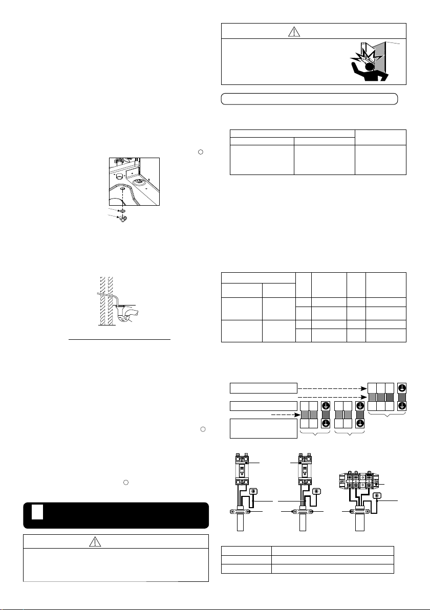
Terminals on the Outdoor Unit
123
Colour of wires (Connecting cables)
Terminals on the Tank unit
LN L1N1123
(Power Supply Cord)
Terminals on the isolating devices
from power supply (Disconnecting
means)
LN L1N1
Power Supply 1 Power Supply 2
Tank Unit/
Outdoor Unit
connection
Power Supply 2 Cable
Power Supply 1 Cable
Terminal
Board
RCCB/ELCB
*1 *1
Connecting Cable
Holder
(Clamper) Holder
(Clamper)
Terminal screw Tightening torque cN•m {kgf•cm}
M4 157~196 {16~20}
M5 196~245 {20~25}
*1 - Earth wire must be longer than other cables for safety reasons


 Operation and maintenance instructions")