Pandora Mini v3 User manual

Product is in conformity with Electromagnetic Compatibility
Directive EMC 2004/108/EC and R&TTE Directive 1999/5/EC
Pandora would like to thank you
for choosing our service-security system
Pandora Light v3
Pandora Light v3 is a car service-security system built for cars with on-board voltage of 12V. It is a
complex engineering device, which includes unique and modern technological software and hardware
solutions.
While developing the Pandora Light v3 we were using the most up-to-date electronics from world’s
best manufacturers. The device is built using high-precision mounting and control machinery, thus
we guarantee highest possible quality, reliability and stable technical characteristics for the whole
operation period.
The system has a cryptographically strong authorization code with unique dialog algorithm and
individual encryption key on every device. It guarantees protection form electronic hacking for the
whole operation period.
The system is built for your convenience: it’s ergonomic, reliable, has the highest security and service
characteristics, 3 years unconditional warranty and free service and support. We are happy to provide
any support we can – feel free to use our online support.
! WARNING! It’sstRoNGly RecommeNded to INstAll AsecuRIty system by the quAlIfIed peRsoNNel!
the INstAlleR should be Able to mouNt the system usING pRovIded documeNtAtIoN – INstAllAtIoN dIAGRAm,
specIfIc INstAllAtIoN GuIdes ANd specIAl softWARe developed ANd tested by ouR eNGINeeRs. most of the feAtuRes
ARe depeNds of AcoRRect coNNectIoN ANd coNfIGuRAtIoN of the seRvIce-secuRIty system, so If the ceRtAIN feAtuRe
doesN’tWoRk As expected, most lIkely the pRoblem Is RelAted to ImpRopeR INstAllAtIoN.
This device has limited external factors resistance. It should be operated in temperatures outside from -40 to +850C range. All system
components must be installed only in a car interior. The base unit and radio tags fulfil with the IP40 category of protection against water.
Our web-site: pandorainfo.com

3
2USER AND INSTALLATION MANUALPANDORA LIGHT V3
Table of contents
General information 4
System set 4
Read before using 5
PIN-codes of the system 6
Owner’s personal card 6
External VALET button 7
System modules layout 7
Base unit 8
Information signals of the system 9
System functions and modes 11
Security mode 11
Control and security zones 11
Remote and automatic engine starts 12
Slave mode 13
Code immobiliser (pin to drive) function 14
Beach mode 14
Checking the number of paired devices 15
Remote control D-010 16
Switching on/off remote control 16
Meaning of the LED SEND/ALARM indicator signals 17
Replacing the remote control battery 17
Quick access functions 18
Icons of the remote control 19
Engine heater. Time channels 22
Check car status 23
Event history. Automatic engine start 24
Shock/motion/tilt sensor settings 27
System installation 30
General installation requirements 30
Base unit connectors description 31
Wiring diagram 32
Remote control D-010 35
Siren signal settings 37
Sound notification settings 38
Radio channel control settings 38
Service/Valet mode 39
Time settings. Alarm clock settings 40
Control the system 41
Arming 41
Disarming 42
Unlocking the trunk 42
Locking/unlocking doors when ignition is on 43
Delayed arming 43
Car search function 44
PANIC mode 44
Remote engine start 45
«Hold On» mode 46
Engine preheater 46
Service mode 47
Control over the system in case of emergency 48
Emergency disarming/Beach mode off 49
Emergency control of the code immobiliser 50
Programming the system 51
Additional devices 57
Warranty obligations 59
Installation certificate 63
Acceptance certificate 64
Warranty Card 64

5
4USER AND INSTALLATION MANUALPANDORA LIGHT V3
GENERAL INFORMATION
System set
1. User and installation manual 1
2. Owner’s personal card 1
3. Main remote control D-010 1
4. Additional remote control R-387 1
5. Base unit 1
6. External VALET button 1
7. External temperature sensor 1
8. Relay module RMD-5M 1
9. Main cable of the base unit 1
10. LIN-interface cable 1
11. IMMO-KEY interface cable 1
12. Fastening kit 1
13. Packaging 1
.
! NOTE! ThE maNufacTurEr rEsErvEs ThE righT TO chaNgE ThE sysTEm sET aNd cONsTrucTiON Of ThE prOducT TO imprOvE iT’s
TEchNOlOgical aNd OpEraTiONal paramETErs wiThOuT NOTificaTiON.
Read before using
Carefully read this manual before starting installation and using the security-service system. Pay
attention to text marked with !
!ThE sEcuriTy-sErvicE sysTEm is acOmplEx TEchNical prOducT. sysTEm iNsTallaTiON aNd cONfiguraTiON musT bE carriEd
OuT ONly by askillEd prOfEssiONal.
!fEaTurEs aNd sysTEm mOdEs, cONTrOl Of ThE vEhiclE’szONEs dEpENds ON ThE TypE Of cONNEcTiON aNd sysTEm sETTiNgs,
OrigiNal vEhiclE OpEraTiON lOgic aNd Trim.
! ThE sysTEm sET iNcludEs ThE «OwNEr’spErsONal card». This card cONTaiNs iNfOrmaTiON uNdEr ThE prOTEcTivE layEr
ThaT is iNTENdEd ONly fOr ThE OwNEr Of ThE sysTEm. makE surE ThaT ThE prOTEcTivE layEr ON ThE OwNEr’splasTic card is
iNTacT afTEr ThE iNsTallaTiON Of ThE sysTEm. rEad ThE «OwNEr’spErsONal card» sEcTiON Of This maNual bEfOrE ErasiNg
ThE prOTEcTivE layEr.
! whEN sysTEm iNsTallaTiON is fiNishEd:
• chEck ThE sysTEm OpEraTiON aNd fuNcTiONs wiTh aspEcialisT.
wErEcOmmENd ThaT yOu mark Each wOrkiNg fuNcTiON wiTh asigN iN ThE «cONTrOl ThE sysTEm» sEcTiON.
• chEck ThaT ThE «iNsTallaTiON cErTificaTE» aNd «warraNTy card» arE fillEd OuT. ThEsE dOcumENTs may bE rEquirEd fOr
cONTacTiNg ThE cusTOmEr suppOrT.
• ask aN iNsTallEr TO mark ThE layOuT Of ThE sysTEm cOmpONENTs ON ThE diagram. This iNfOrmaTiON may bE rEquirEd fOr
diagNOsTic/cONfiguriNg Or EmErgENcy dEacTivaTiON Of ThE sysTEm.
• wErEcOmmENd ThaT yOu chaNgE ThE dEfaulT valuE Of ThE piN-cOdEs Of ThE sysTEm. yOu caN wriTE dOwN ThE
chaNgEd piN-cOdEs iN ThE «piN-cOdEs Of ThE sysTEm» sEcTiON.

7
6USER AND INSTALLATION MANUALPANDORA LIGHT V3
PIN-codes of the system
The «Secret PIN-code»
(is written on the «Owner’s personal card»)
The «Service PIN-code»
(default value is 1-1-1-1)
The «Immobiliser PIN-code»
(is used for the Code Immobiliser (pin-to-drive) function)
The «Beach mode PIN-code»
(is used with «Beach mode» enabled)
! iTis rEcOmmENdEd ThaT yOu will wriTE dOwN ThE chaNgEd Or crEaTEd valuEs Of all piN-cOdEs. ElimiNaTE Third-parTy
accEss TO This iNfOrmaTiON.
Owner’s personal card
! ErasE ThE prOTEcTivE layEr carEfully. dONOT usE aNy sharp ObjEcTs TO avOid damagiNg Of hiddEN iNfOrmaTiON uNdEr
ThE prOTEcTivE layEr. ThE iNfOrmaTiON ON ThE OwNEr’spErsONal card cOuld NOT bE chaNgEd Or rEsTOrEd iN casE Of
damagE Or lOsE.
CANNOT BE CHANGED
Service is not available
2-2-2-2
LOGIN / PASS
PIN
External VALET button
(VALET button via CAN)
Button
for the immobiliser PIN
Button
for the «Beach mode» PIN
Circuit being blocked
Base unit
1
2
3
4
5
6
7
8
External VALET button
An external VALET button with a three-color (red, green, orange) status
LED indicator is placed inside a vehicle (see the system modules layout).
The button is used for programming the system, arming/disarming,
activating/deactivating immobiliser mode.
System modules layout
The owner’s personal card contains private information
under a protective layer:
• PIN (the «Secret PIN-code») is a 4-digit number. This
code can be used to disarm the system and to deactivate
immobiliser functions and to activate service mode. It can
be also used to enter programming mode.
• LOGIN/PASS/ Phone number - not used.

9
8USER AND INSTALLATION MANUALPANDORA LIGHT V3
Base unit
868MHz Antenna (dynamic dialog encryption AES 128 bit) supports up to 4 remote controls
D-010, DXL-707/078/077, R-387.
Built-in 3D accelerometer is used to detect shock/motion/tilt including 2 separate zones of shock
sensor (alarm and warning), the system allows to adjust sensitivity of each zone, to use data from the
accelerometer to block the engine and close the central lock on movement.
Temperature sensors allow the system to measure temperature of different zones to send this
information to the remote control. The following zones are available: interior temperature – built in
sensor of the main unit, engine temperature – external temperature sensor (see the «System set»). The
system setting allows you to reassign sensor to different zones and to implement automatic engine or
engine preheater starts and stops by temperature.
Built-in digital 2CAN/LIN* interfaces allow the system to read status end execute commands via
digital buses, and work with Webasto Thermo Top Evo Eberspacher Hydronic 1/2/3.
Built-in digital IMMO-KEY port and immobilser bypass* – hardware and software algorithms
with the special Pandora CLONE server allow the system to bypass original immobilisers for automatic
and remote engine starts.
Built-in micro-USB port – update and configuration of the system using Pandora Specialist mobile
app or Alarm Studio program.
! *mOrE iNfOrmaTiON is availablE ON lOadEr.paNdOraiNfO.cOm
Information signals of the system
LED INDICATOR SIGNALS
SIGNALS DESCRIPTION
THE SYSTEM IS ARMED
Short red ashes System is armed
Fast red ashes Alarm
THE SYSTEM IS DISARMED
Faded System is disarmed
Red System is preparing for automatic or delayed arming
Green (when ignition is on) System is in service mode
Orange ashes (when switching on the ignition) Conrms the number of paired remotes
WHEN ENTERING THE «SECRET PIN-CODE» OR THE «SERVICE PIN-CODE»
Orange ash Conrms a VALET button press
Short red ash Conrms a digit input
PIN-code is incorrect
Red and green ashes Conrms correct PIN code

11
10 USER AND INSTALLATION MANUALPANDORA LIGHT V3
SOUND AND LIGHT SIGNALIZATION
SIGNALS
(sound / light) DESCRIPTION
1х /1х Arming
2х /2х Disarming
5х /5х Car search
30sec. /30sec. Alarm - alarm level of a sensor is triggered, PANIC mode
3х Remote/automatic engine start procedure indication
3х /1х Warning level of a sensor is triggered
4х /4х «Sensors were triggered» signal when disarming
Parking light is not turned o notication
«Sensors are triggered» signal when arming
BEEPER SOUND SIGNALS
SIGNAL DESCRIPTION
1 sound signal Activating service mode
2 sound signals Deactivating service mode
1 sound signal Correct input of the «Immobiliser PIN-code»
! sirEN aNd bEEpEr arE NOT iNcludEd iN ThE sysTEm sET.
SYSTEM FUNCTIONS AND MODES
Security mode
The system confirms arming with 1х sound and 1х light signals. When the system is armed, the
system monitors security zones with separated warning and alarm level of triggering:
• Warning mode - this mode activates when there is a slight impact on the shock sensor or additional
senor. It is accompanied with 1х light and 3х sound signals;
• Alarm mode - this mode activates when a sensor or one of the security zones is triggered. It is
30 sec. light and 30 sec. sound signals. The alarm signals can be cancelled by an arming
or disarming command.
If one of the security zones is triggered the system:
• records this event in its non-volatile memory;
• activates the alarm or warning mode;
• informs an owner by all available means;
• blocks the engine (in accordance with the settings and connections).
If one of the security zones is opened at the moment of arming, the system will produce 4х
sound and 4х light warning signals.
If one of the security zones fails, the system will forcibly turn off this zone. If a switch triggers
more than 9 times in a row, it will be disabled until the next arming. The shock/tilt/motion sensor is
temporarily deactivated (15 sec.) if it has been triggered more than 3 times in a row.
The system confirms disarming with 2х sound and 2х light signals. The system deactivates
engine blocking (if the immobiliser function and additional blocking are not used). If there were alarm
events (except warning level) during the armed period, the system will produce 4х sound and
4х light warning signals. The system continues to display all zones when it is disarmed, but the
information is not saved in the memory.
! ThE sysTEm cONTiNuEs TO display all zONEs whEN iT is disarmEd, buT ThE iNfOrmaTiON is NOT savEd iN ThE mEmOry.
Controlled and security zones
• Interior temperature (status)
• Engine temperature (status)
• Voltage of the on-board circuits (status)
• Engine operation control - RPM (status)

13
12 USER AND INSTALLATION MANUALPANDORA LIGHT V3
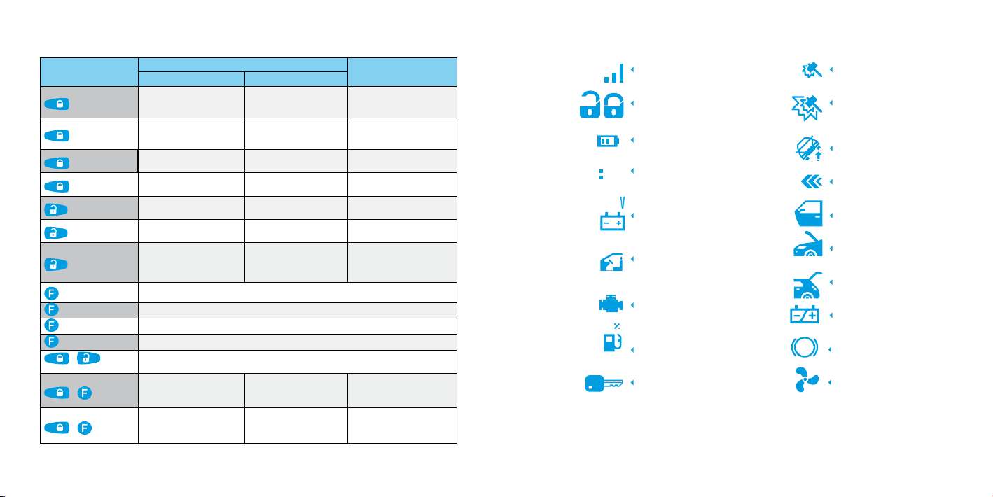
• Heater operating control (status)
• Fuel level (status)
• Parking (automatic gearbox) /Handbrake (manual gearbox) status
• Parking light is not turned off notification (status)*
• Shock sensor (security zone – alarm and warning level)
• Motion sensor (security zone – alarm level)
• Tilt sensor (security zone – alarm level)
• OE alarm system status*, additional sensor** (status, security zone – alarm and warning level)
• Turning ignition on (status, security zone – alarm level)
• Opening doors (status, security zone – alarm level)
• Opening a hood (status, security zone – alarm level)
• Opening a trunk (status, security zone – alarm level)
• Pressing brake (status, security zone – alarm level)
* availablE via caN-bus (sEE lOadEr.paNdOraiNfO.cOm)
** OpTiON (NOT iNcludEd iN ThE sysTEm sET).
Remote and automatic engine starts
The system allows the remote engine start using the “remote engine start” command from a remote
control or preconfigured automatic engine start function. Remote start can be used to heat engine and
interior, charge battery or to cool the interior with air conditioning.
Remote and automatic starts can only be used when the system is armed . While the system
is in remote or automatic start mode, it keeps performing all security functions of all security zones
excluding a shock sensor and additional sensor (the system can be configured not to disable
sensors during a remote engine start). To compensate it, the motion sensor sensitivity will be
increased and it’s responsiveness will be reduced. If any security zone will be triggered, the engine
will be immediately stopped and alarm mode will be triggered.
When using the remote and automatic engine start functions, make sure that a car is secured with
handbrake or some other means of fixating the car on a parking position.
Remote and automatic engine start on automatic transmission cars will only occur, if a transmission
selector lever was left in the «P» position.
If a car has manual transmission, remote or automatic start will only occur if the program neutral
procedure was followed when the car was arming.
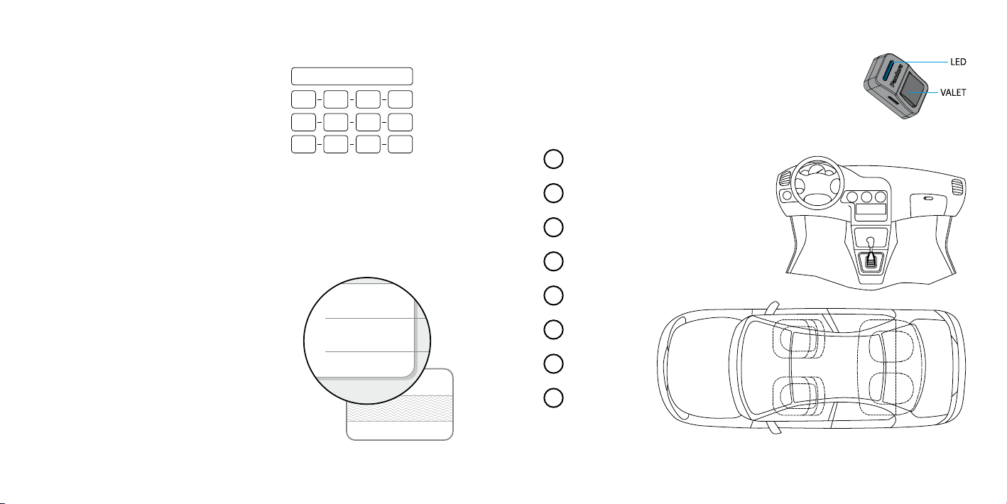
An example of the program neutral procedure
1. When the engine is running, fixate the car with the handbrake and put gear lever to the neutral
position. Program neutral procedure will be switched on automatically (by default system settings).
2. Turn the key in the ignition lock to the OFF position (the engine should still be running) and take it
out of the lock (skip this step for cars with a Start/Stop button).
3. Leave the car, close the doors.
4. Arm the system - the engine will be stopped. Now the system is ready to perform remote and
automatic engine start.
Automatic starts
The system allows configuring automatic engine start and stop conditions using a remote control.
The following conditions can be specified for automatic engine starts: schedule, time period, engine
temperature, voltage. The engine will be stopped automatically after specified time or when the engine
temperature reaches a specified value. The engine can be also stopped by a user command.
!auTOmaTic ENgiNE sTarTs aNd sTOps by TEmpEraTurE arE availablE ONly if ENgiNE TEmpEraTurE daTa is availablE iN digiTal
busEs Of ThE car, Or if aN ExTErNal ENgiNE TEmpEraTurE sENsOr is cONNEcTEd. rEmOTE aNd auTOmaTic ENgiNE sTarTs arE
NOT availablE if ThE hOOd is OpEN.
afTEr asEriEs Of ThrEE uNsuccEssful aTTEmpTs Of auTOmaTic sTarT, all fOllOwiNg auTOmaTic sTarTs will bE caNcElEd
uNTil disarmiNg/armiNg (This dOEs NOT affEcT ON rEmOTE ENgiNE sTarT).
Slave mode
This mode allows arming and disarming vehicle control elements – factory key fob, buttons/sensors of
a keyless access entry system.
Slave mode can be implemented using analog connections or a digital protocol of a vehicle.
!This mOdE is disablEd by dEfaulT - cONfiguraTiON Of ThE sysTEm shOuld bE madE by aqualifiEd TEchNiciaN. TOiNcrEasE
ThE aNTi-ThEfT fuNcTiONaliTy Of ThE slavE mOdE iT is rEcOmmENdEd TO usE ThE disablE ENgiNE blOckiNg fuNcTiON whEN
«immObilisEr piN-cOdE» ENTErEd (sEE cOdE immObilisEr (piN TO drivE) fuNcTiON)

15
14 USER AND INSTALLATION MANUALPANDORA LIGHT V3
Code immobiliser (pin to drive) function
This function allows to use the pre-programmed «Immobiliser PIN-code» to disable the engine blocking,
service mode, disarming the security system. The code must be entered using factory vehicle controls
(buttons/lever/pedal) and/or additionally installed elements.
In case of emergency it is possible to disable code immobiliser by methods, described in «Control the
system in case of emergency».
AN EXAMPLE OF USING THE FUNCTION
• Turn on the ignition to disable engine blocking or service mode, turning on the ignition is not
required if you want to disarm the system or control time channels.
• Enter the «Immobiliser PIN-code», code can consist max of 4 digits from 1 to 9.
- Press the pre-programmed button/lever/pedal the number of times equals to the first digit.
- Pauses between presses should not exceed 1 second. More than 1 second pause will be interpreted
as the start of the next digit input.
• The system will confirm the correct input by a sound signal of the beeper and will activate a
programmed action.
!This mOdE is disablEd by dEfaulT - cONfiguraTiON Of ThE sysTEm shOuld bE madE by aqualifiEd TEchNiciaN.
EmErgENcy disabliNg Of ThE cOdE immObilisEr is madE wiTh ThE «sEcrET piN-cOdE» aNd valET buTTON (sEE «dEacTivaTiNg
cOdE immObilisEr (piN-TO-drivE)»).
Beach mode
This mode allows to use the pre-programmed «Beach mode PIN-code» for system arming/disarming.
The code must be entered using factory vehicle controls (buttons/sensors) or additionally installed
element.
When using the Beach mode system disarming is possible only by entering «Beach mode PIN-code»
or «Secret PIN-code» by a VALET button (see «Control the system in case of emergency»)
AN EXAMPLE OF USING BEACH MODE
• Press the factory or additionally installed element until the single light flash, thereafter start to enter
«Beach mode PIN-code».
• Enter the «Beach mode PIN-code», code can consist max of 4 digits from 1 to 9:
- Press the the control element the number of times equals to the first digit.
- Pauses between presses should not exceed 1 second. More than 1 second pause will be interpreted
as the start of the next digit input.
• After the correct input the system will confirm arming/disarming by the sound and light signals.
!This mOdE is disablEd by dEfaulT - cONfiguraTiON Of ThE sysTEm shOuld bE madE by aqualifiEd TEchNiciaN.
EmErgENcy disabliNg Of ThE sysTEm is madE wiTh ThE «sEcrET piN-cOdE» aNd valET buTTON (sEE «cONTrOl ThE sysTEm
iN casE Of EmErgENcy»)
Checking the number of recorded remote controls
The number of recorded remote controls can be checked by the number of flashes of the LED
indicator on the VALET button or on the base unit.The number of registered remote controls device can
be checked every time the ignition is switched on when the system is disarmed. The number of orange
LED flashes will indicate the number of recorded remote controls.
You can also check the number of recorded remote controls by taking off and putting back on battery
terminal. The system will emit short sound signals from a siren , with less than 1 sec. interval. The
number of the signals equals to the number of recorded remote controls.

17
16 USER AND INSTALLATION MANUALPANDORA LIGHT V3
REMOTE CONTROL D010
A two-way remote control is a mean to control and display system and vehicle state. The remote
control operates only when it is in the coverage zone of the system radio channel.
All transmitted commands are reliably protected against electronic hacking with a modern dynamic
dialogue encryption algorithm. For easily distinguishable notifications the remote uses 16 ringtones.
Each ringtone matches a particular event. Remote has flashing LED indicators for additional information.
Switching on/o the remote control
The remote is fully operational when shipped. To switch on the remote, press and hold the button
for 3 seconds. The «REMOTE ON» ringtone will play (change the battery if the remote control does not
switch on). Pressing and holding this button again for 3 seconds will cause the remote to switch off.
!all cONTrOl cOmmaNds arE TraNsmiTTEd via radiO chaNNEl, fOr maximum EffEcTivENEss aNd raNgE iT is rEcOmmENdEd
NOT TO shiEld aNTENNa (sEE picTurE) wiTh fiNgErs whEN usiNg arEmOTE cONTrOl.
Antenna
868 MHz
Indicator
SEND/ALARM
OLED-
display
Arming
Disarming Open Trunk
Turn on/o button
Sound source
12
12 0V 48
Meaning of the LED SEND/ALARM indicator signals
Green indicator «SEND»:
• Flashes if there is a connection with the base unit
• Goes dark when there is no connection with the base unit.
Red indicator «ALARM»:
• Flashes frequently if there is any notification
• Flashes occasionally when there is no connection.
Replacing the remote control battery
If high quality batteries are used, service-security
system remote can function up to 4 months without
needing a replacement. Battery needs to be replaced
if the remote control is not turning on or the icon
has only one bar left and starts flashing.
To change the battery:
• move the battery cover in the direction of the
arrow;
• remove the battery from the battery compartment
and, observing the polarity, insert a new one;
• close the battery cover;
• the remote is ready for use (switch the remote on
by pressing for 3 seconds.
!iTis rEcOmmENdEd TO havE asparE aaa baTTEry iN ThE car.

19
18 USER AND INSTALLATION MANUALPANDORA LIGHT V3
Quick access functions of the remote control
System is disarmed System is armed
(no alarm events)
Ignition is switched on Ignition is switched o
(short press) Lock doors without arming Arming with sound
conrmation
Search mode – ashes of
turn signals with sound
signals for 5 seconds
(1 sec.) Arming without sound
conrmation
Search mode – ashes of
turn signals without sound
signals for 5 seconds
(2 sec.) Switch on «Hold On» mode
(3 sec.) Switch on «Programmed
neutral» Remote engine start
(short press) Unlock doors Unlock doors Disarming with sound
conrmation
(1 sec.) Disarming without sound
conrmation
(>2 sec.) Switch o «Hold On» mode Switch o the ignition
during remote or automatic
engine start procedure.
(short press) Switch on display
(1 sec.) Unlock trunk
(2 sec.) Switch on/o time channel
(3 sec.) Switch on/o remote
+
(short press) PANIC mode
+ (short press)
Arming when the
engine is running with
sound conrmation
Arming in 30 seconds
with sound notication
+ (1 sec.)
Arming when the
engine is running without
sound conrmation
Arming in 30 seconds
without sound
notication
Icons of the remote control
*Separate display indication of doors, factory alarm status, engine temperature depends on the information in CAN-bus digital protocol of
specific car. Fuel level indication depends on the information in CAN-bus digital protocol, or on the fuel level sensor analog output signal
(require additional connection).
Flashing when
command sending
Security mode status
Remote control
battery level
Current time
Battery voltage
Interior temperature
Engine
temperature
Fuel level*
Ignition
Security zone
12 48
Shock sensor security zone
Warning level
Shock sensor security zone
Alarm level
Tilt sensor security zone
Motion sensor security zone
Doors security zone*
Front hood security zone
Trunk security zone
Low voltage security zone
Brake pedal security zone
Engine operation icon
P
22
°
90
°
55
1
2
.4

21
20 USER AND INSTALLATION MANUALPANDORA LIGHT V3
entering settings menu
•
•
• control over engine heater
engine
preheater
12 48
0
engine
preheater:
enabled
engine
preheater:
disabled
remote start
settings
system
controls
CHECK
channel
controls
1 2 3
4 5 6
78 9
27°24°12 0V
30
system
controls
CHECK
remote start
settings
system
controls
CHECK
channel
controls
1 2 3
4 5 6
78 9
sounds
disables
sounds
enabled
sounds
siren settings
siren settings
siren settings
siren sounds
Remote control menu
Briefly press the , button to enter the menu. The following presses of the button will switch
between menu items.
• control over time channels
• control over car status, view event history
• remote and automatic engine start
settings
• shock/motion/tilt sensors settings
• siren sounds adjusting
sensors
adjusting
• sound notifications of the remote
control
• notification on loss of radio signal
• service mode
• time setting
• alarm clock setting
• alarm clock time adjusting
exit settings menu
To exit menu without saving, press and
hold button for 1 sec.
valet mode
disabled
valet mode
valet mode
enabled
14 45
06 30
alarm clock
enabled
alarm clock
disabled
alarm clock
sounds
disables
sounds
enabled
sounds
siren settings
siren settings
siren settings
siren sounds
14 45
06 30
alarm clock
enabled
alarm clock
disabled
alarm clock
connect. lost:
melody
connect. lost:
alarm
connect. lost:
no sound
14 45
06 30
alarm clock
enabled
alarm clock
disabled
alarm clock

23
22 USER AND INSTALLATION MANUALPANDORA LIGHT V3
Engine heater
To switch on engine preheater, select «ENGINE PREHEATER MENU» and shortly press button. To
switch off preheater, shortly press button. If preheater monitoring is enabled, LCD will display
icon during engine preheater operation.
!iTis NEcEssary TO makE addiTiONal cONNEcTiONs TO cONTrOl ThE ENgiNE hEaTEr.
Time channels
Time channels can be used to implement additional functions and to control external devices.
To enter «CHANNEL CONTROLS», shortly press button. The following presses of
button will cause switching between channels. To activate/deactivate the channel, shortly press
.
To exit menu without saving, press and hold button for 1 second.
!iTis NEcEssary TO makE addiTiONal cONNEcTiONs TO cONTrOl TimE chaNNEls.
engine
preheater
12 48
0
engine
preheater:
enabled
engine
preheater:
disabled
engine
preheater
12 48
0
engine
preheater:
enabled
engine
preheater:
disabled
• Preheater operation is disabled• Preheater operation is enabled
on off
channel
controls
1 2 3
4 5 6
78 9
1channel 1
disabled
2канал 2
выключен
3канал 3
выключен
4канал 4
выключен
1channel 1
enabled
2канал 2
включен
3канал 3
включен
4канал 4
включен
channel
controls
1 2 3
4 5 6
78 9
1channel 1
disabled
2канал 2
выключен
3канал 3
выключен
4канал 4
выключен
1channel 1
enabled
2канал 2
включен
3канал 3
включен
4канал 4
включен
channel
controls
1 2 3
4 5 6
78 9
1channel 1
disabled
2канал 2
выключен
3канал 3
выключен
4канал 4
выключен
1channel 1
enabled
2канал 2
включен
3канал 3
включен
4канал 4
включен
• shortly press button to switch between channels 2,3 and 4.
27°24°12 0V
30
system
controls
CHECK
27°24°12 0V
30
system
controls
CHECK
Check car status
To receive information about engine, interior temperature, battery voltage and fuel level, select
«SYSTEM CONTROLS» menu and shortly press button.
To exit menu without saving, press and hold button for 1 second.
entering menu
entering menu
on / off
choosing channel

25
24 USER AND INSTALLATION MANUALPANDORA LIGHT V3
Event history
To view event history in the system’s memory, select «SYSTEM CONTROLS» menu, then shortly press
button.
Navigate several last events using (forward) and (back) buttons. Events are displayed by
showing time of the event and flashing corresponding trigger zone indicators.
To exit menu without saving, press and hold button for 1 second.
Automatic engine start
Shortly press button to enter «REMOTE START SETTINGS» menu. Shortly press button to switch
between menu sublevels. Sub-level values are changed using and buttons.
When the settings are changed, the values should be saved. To do this, press button to move to
«SEND» sublevel and press button to save new changes. Changes will be sent to the base unit, it
will be confirmed with double sound signal of the remote.
To exit menu without saving, press and hold button for 1 second.
!ifyOu havE NOT savEd NEw sETTiNgs, rEmOTE aNd auTOmaTic ENgiNE sTarT sETTiNgs will rEmaiN ThE samE as bEfOrE.
entering menu
back forward
27°24°12 0V
30
system
controls
CHECK
arming
12:43
disarming
12:44
remote start
settings
send settings
start by time
enabled
start by time
disabled
daily start
enabled
daily start
disabled
stop by temp
enabled
stop by temp
disabled
start by temp
enabled
start by time
disabled
work
duration
20 min
start temp
– 20°
stop temp
80°
start time
07:30
• enable/disable daily automatic engine starts by time. Set the start time in «START TIME» menu
• setting automatic engine start time for daily starting
remote start
settings
send settings
start by time
enabled
start by time
disabled
daily start
enabled
daily start
disabled
stop by temp
enabled
stop by temp
disabled
start by temp
enabled
start by time
disabled
work
duration
20 min
start temp
– 20°
stop temp
80°
start time
07:30
remote start
settings
send settings
start by time
enabled
start by time
disabled
daily start
enabled
daily start
disabled
stop by temp
enabled
stop by temp
disabled
start by temp
enabled
start by time
disabled
work
duration
20 min
start temp
– 20°
stop temp
80°
start time
07:30
remote start
settings
send settings
start by time
enabled
start by time
disabled
daily start
enabled
daily start
disabled
stop by temp
enabled
stop by temp
disabled
start by temp
enabled
start by time
disabled
work
duration
20 min
start temp
– 20°
stop temp
80°
start time
07:30
hours minutes
entering menu
on off
• enable/disable automatic engine start by engine temperature sensor. Set the starting temperature
in «START TEMP» menu
remote start
settings
send settings
start by time
enabled
start by time
disabled
daily start
enabled
daily start
disabled
stop by temp
enabled
stop by temp
disabled
start by temp
enabled
start by time
disabled
work
duration
20 min
start temp
– 20°
stop temp
80°
start time
07:30
remote start
settings
send settings
start by time
enabled
start by time
disabled
daily start
enabled
daily start
disabled
stop by temp
enabled
stop by temp
disabled
start by temp
enabled
start by time
disabled
work
duration
20 min
start temp
– 20°
stop temp
80°
start time
07:30
on off

27
26 USER AND INSTALLATION MANUALPANDORA LIGHT V3
remote start
settings
send settings
start by time
enabled
start by time
disabled
daily start
enabled
daily start
disabled
stop by temp
enabled
stop by temp
disabled
start by temp
enabled
start by time
disabled
work
duration
20 min
start temp
– 20°
stop temp
80°
start time
07:30
increase decrease
increase decrease
remote start
settings
send settings
start by time
enabled
start by time
disabled
daily start
enabled
daily start
disabled
stop by temp
enabled
stop by temp
disabled
start by temp
enabled
start by time
disabled
work
duration
20 min
start temp
– 20°
stop temp
80°
start time
07:30
• setting the starting temperature for the automatic engine start
• setting the engine work duration for the remote and automatic engine start
remote start
settings
send settings
start by time
enabled
start by time
disabled
daily start
enabled
daily start
disabled
stop by temp
enabled
stop by temp
disabled
start by temp
enabled
start by time
disabled
work
duration
20 min
start temp
– 20°
stop temp
80°
start time
07:30
remote start
settings
send settings
start by time
enabled
start by time
disabled
daily start
enabled
daily start
disabled
stop by temp
enabled
stop by temp
disabled
start by temp
enabled
start by time
disabled
work
duration
20 min
start temp
– 20°
stop temp
80°
start time
07:30
on off
• enable/disable repeating engine starts after period of time (default value is 2 hours). Set the period
time in the settings of the main unit
remote start
settings
send settings
start by time
enabled
start by time
disabled
daily start
enabled
daily start
disabled
stop by temp
enabled
stop by temp
disabled
start by temp
enabled
start by time
disabled
work
duration
20 min
start temp
– 20°
stop temp
80°
start time
07:30
remote start
settings
send settings
start by time
enabled
start by time
disabled
daily start
enabled
daily start
disabled
stop by temp
enabled
stop by temp
disabled
start by temp
enabled
start by time
disabled
work
duration
20 min
start temp
– 20°
stop temp
80°
start time
07:30
on off
• enable/disable the setting that allows to stop remote or automatic engine start when engine
temperature increases. Set the engine stop temperature in «STOP TEMP» menu.
increase decrease
remote start
settings
send settings
start by time
enabled
start by time
disabled
daily start
enabled
daily start
disabled
stop by temp
enabled
stop by temp
disabled
start by temp
enabled
start by time
disabled
work
duration
20 min
start temp
– 20°
stop temp
80°
start time
07:30
remote start
settings
send settings
start by time
enabled
start by time
disabled
daily start
enabled
daily start
disabled
stop by temp
enabled
stop by temp
disabled
start by temp
enabled
start by time
disabled
work
duration
20 min
start temp
– 20°
stop temp
80°
start time
07:30
return to the beginning of the settings
set selected modes
• set the engine stop temperature
Shock/motion/tilt sensor settings
To enter the remote sensor adjusting menu shortly press button and choose «SENSOR ADJUSTING»
menu and shortly press button.
Shortly press button to switch between menu sublevels of the shock/motion/tilt sensors. The
sensitivity of a sensor are increased using button and decreased using button. Maximum
sensitivity value is 50 and minimum is 0.
Press and hold button for 1 second to save new sensitivity level.
sensors
adjusting
shortly press
to enter menu

29
28 USER AND INSTALLATION MANUALPANDORA LIGHT V3
Additional sensor settings
For a prompt remote adjusting of the additional sensor control, select «ADD. SENSOR» submenu by
short presses of button. Short presses of the button will cause switching between modes. To
save new settings of values of the additional sensor control, shortly press button.
For a prompt remote adjusting of the additional sensor security zones, select «ADJUSTING ADD
SENSOR WARN LVL» or «ADJUSTING ADD SENSOR ALARM LVL» submenu by short presses of button.
Sensor sensitivity can be set with short presses of and button.
датчик удара
предвар. уров.
shock sensor
warn level
disabled
датчик удара
предвар. уров.
включен
датчик удара
тревож. уров.
датчик удара
датчик удара
тревож. уров.
включен
adjusting
shock sensor
warn. lvl. = 35
adjusting
shock sensor
alarm lvl. = 30
shock sensor
enabled
add. sensor
enabled
add. sensor
alarm level
disabled
add. sensor
warn level
disabled
adjusting
add. sensor
alarm lvl. = 25
adjusting
add. sensor
warn. lvl. = 40
shock sensor
alarm level
disabled
shortly press
to save
choose mode
датчик удара
предвар. уров.
shock sensor
warn level
disabled
датчик удара
предвар. уров.
включен
датчик удара
тревож. уров.
датчик удара
датчик удара
тревож. уров.
включен
adjusting
shock sensor
warn. lvl. = 35
adjusting
shock sensor
alarm lvl. = 30
shock sensor
enabled
add. sensor
enabled
add. sensor
alarm level
disabled
add. sensor
warn level
disabled
adjusting
add. sensor
alarm lvl. = 25
adjusting
add. sensor
warn. lvl. = 40
shock sensor
alarm level
disabled
shortly press
to save
датчик удара
предвар. уров.
shock sensor
warn level
disabled
датчик удара
предвар. уров.
включен
датчик удара
тревож. уров.
датчик удара
датчик удара
тревож. уров.
включен
adjusting
shock sensor
warn. lvl. = 35
adjusting
shock sensor
alarm lvl. = 30
shock sensor
enabled
add. sensor
enabled
add. sensor
alarm level
disabled
add. sensor
warn level
disabled
adjusting
add. sensor
alarm lvl. = 25
adjusting
add. sensor
warn. lvl. = 40
shock sensor
alarm level
disabled
shortly press
to save
choose mode
To save new settings of the sensor, press and hold button for 1 second.
To exit menu without saving, press and hold button for 1 second.
Shock sensor settings
For prompt remote adjusting of shock sensor control, select «SHOCK SENSOR» submenu by short
presses of button. Short presses of button will cause switching between modes. To save new
settings of values of the shock sensor control, shortly press button.
датчик удара
предвар. уров.
shock sensor
warn level
disabled
датчик удара
предвар. уров.
включен
датчик удара
тревож. уров.
датчик удара
датчик удара
тревож. уров.
включен
adjusting
shock sensor
warn. lvl. = 35
adjusting
shock sensor
alarm lvl. = 30
shock sensor
enabled
add. sensor
enabled
add. sensor
alarm level
disabled
add. sensor
warn level
disabled
adjusting
add. sensor
alarm lvl. = 25
adjusting
add. sensor
warn. lvl. = 40
shock sensor
alarm level
disabled
датчик удара
предвар. уров.
shock sensor
warn level
disabled
датчик удара
предвар. уров.
включен
датчик удара
тревож. уров.
датчик удара
датчик удара
тревож. уров.
включен
adjusting
shock sensor
warn. lvl. = 35
adjusting
shock sensor
alarm lvl. = 30
shock sensor
enabled
add. sensor
enabled
add. sensor
alarm level
disabled
add. sensor
warn level
disabled
adjusting
add. sensor
alarm lvl. = 25
adjusting
add. sensor
warn. lvl. = 40
shock sensor
alarm level
disabled
press for
1 second to save
press for
1 second to save
increase decrease
increase decrease
датчик удара
предвар. уров.
shock sensor
warn level
disabled
датчик удара
предвар. уров.
включен
датчик удара
тревож. уров.
датчик удара
датчик удара
тревож. уров.
включен
adjusting
shock sensor
warn. lvl. = 35
adjusting
shock sensor
alarm lvl. = 30
shock sensor
enabled
add. sensor
enabled
add. sensor
alarm level
disabled
add. sensor
warn level
disabled
adjusting
add. sensor
alarm lvl. = 25
adjusting
add. sensor
warn. lvl. = 40
shock sensor
alarm level
disabled
shortly press
to save
choose mode

31
30 USER AND INSTALLATION MANUALPANDORA LIGHT V3
SYSTEM INSTALLATION
General installation requirements
• Install the base unit only inside car interior.
• Install securely each system’s component, as conditions of the car standard operation can harm
functionality of the alarm system and cause damage to the car’s systems, including the elements
of safety in motion.
• The system installation should be performed when the system base unit connectors and the
negative battery terminal are disconnected.
• The base unit power supply should be switched off when connecting to CAN-bus. The system
installation can be performed via twisting together or via lead tin soldering followed by isolation of
a connection points.
• When connecting the wires together, pay attention to cross-sections and materials of connected
conductors, if they are different, bring electrochemical potentials to the minimal difference. The
isolation should not allow for moisture to reach wiring, as the presence of moisture will increase
electrochemical destruction of wires (this is especially important for the high-current circuits).
• Connection points should be placed as high as it is possible so water condensate will not form drops
on them.
• To avoid the destruction of compounds by car vibration, ensure that there is a bit of free length to
the wiring, providing enough sagging.
• Do not allow wiring in places where the wires isolation can be damaged by abrasion.
• Electronic system units should be placed connectors down and as high as possible to avoid
condensate reaching electronic components through the connectors.
• When installing base unit, secure it to the car body for correct operation of in-built shock sensor.
• All unused system wires during the installation must be insulated and secured to prevent accidental
touching of a car body or other wires.
Base unit connectors description
X1 connector (LIN)
This connector is used for connection to the vehicle’s digital buses or digital control lines of the engine
heater/pre-heater Webasto Thermotop EVO and Eberspacher Hydronic 1/2/3.
Х2 connector (micro-USB)
This connector is used for system setting and software update of the main unit using Pandora Alarm
Studio program or Pandora Specialist (Android) mobile application.
Х3 connector (Analog temperature sensor)
This connector is used to connect external temperature sensor. In the system settings it has a default
value «External analog» with the logic «Engine temperature». Sensor could be reassigned to determine
the interior temperature.
Х4/Х5 connector (Main and additional connector of the main unit)
The main connector contains low-current programmable channels, inputs «INP» and outputs «CH».
Changing of the default logic is available in the system settings «Inputs and Outputs» or «Time
channels». Additionally, in the «Input settings» section it is possible to change the «INP» channels from
the normally open «NO» type (the system reacts on the appearance of the potential) to the normally
closed «NC» type (the system reacts on the disappearance of the potential).
X6 connector (External VALLET button)
The connector is used to connect external VALET button.
Х7 connector (Multifunctional port)
This connector contains multifunctional programmable channels used for implementing input «INP»
logic or implementing of the bypass procedure of the original immobiliser «IMMO-KEY». Deselect any
logic of the inputs «INP» in the settings if the bypass procedure implementing. The immobiliser bypass
procedure must be implemented according to the installation schemes available on loader.pandorainfo.
com, Pandora Alarm Studio, Pandora Specialist.

33
32 USER AND INSTALLATION MANUALPANDORA LIGHT V3
Pandora
model:
LIGHT v3
WARNING! Before starting the installation of the
system: check the connection points on
loader.pandorainfo.com, Pandora Specialist, Pandora
Alarm Studio, update system rmware, choose a car
model if connecting to CAN-bus.
(+)
micro-USB Analog temperature sensor
VALETLED/CAN
X4
X7
X6
X5
X2
X4 X5 X6 X7X3 X1
INP2 – «Doors switch»
1
2
«Tachometer input»
CH5 – «Open trunk» output
CAN2-L/CH2
CAN1-H
CAN1-L
CH3
– «Turn indicators»
CAN2-H/CH4
CH1 – «Beeper output»
INP4 – «Neutral/Handbrake input»
CH11 – «Siren» (+12V)
INP6 – «Ignition input»
INP3 – «Front hood switch»
150mA (-)
(-)
(-)
200 mA (-)
(-)
200mA (-)
(-) 200mA
150mA (-)
INP5
– «Brake pedal» /«Fuel level input»
GROUND
3
4
5
6
7
8
16 Red
15 Purple
14 Yellow
13
Blue/Black
12 Yellow/Black
Yellow/White
Orange/White
Red/Black
11 Orange/Black
10 Brown/White
White
9Blue
Blue/White
Green
Grey
Black
X3
X1
Antenna 868 MHz
POWER SUPPLY (+12V)
2А (+)
(+)
(Uamp3...100V, min 8Hz)
WARNING! The base unit and system elements must be
installed in places with appropriate temperature, moisture
and dust protection characteristics (IP40 - interior, IP54 and
higher - interior, engine compartment).
WARNING! All power circuits of additional devices that are
not powered through the base unit of the system should
have their own fuses.
WARNING! The security system is a maintenance-free
device. In case of failure you must immediately
contact local specialized service center.
IT IS FORBIDDEN to install the system on a car with
normal voltage other than 12V.
IT IS FORBIDDEN to install the security system with
damaged output cables.
IT IS FORBIDDEN to exclude or change the nominal
of the fuses provided with the security system when
connecting to the vehicle's wiring.
Relay module
(scheme is
on the next page)
3 6
52
1 4
Red
+ 12V
CH10
«Starter»
CH8
«Bypass»
CH7
«Blocking NO»
«АСС»/
CH6
«Brake pedal»*
«Ignition»/
CH9 «Button»*
Brown
Yellow
Orange
Green
Blue
* For remote start implementation by Start/Stop algorithm
Black
2
White
1
LIN-Input
LIN-Output
External VALET button
LED
VALET
White
2
Black
3
Green
1
IMMO-KEY2 OUT/INP7
IMMO-KEY1 IN
IMMO-KEY1 OUT/INP1
«Trunk switch»
X2
R20
+12B
200mA (-)
200mA (-)
200mA (-)
200mA (-)
200mA (-)
IT IS FORBIDDEN to install the temperature sensor at
the place where temperature is higher than the
operating range of the sensor (+125°C) and cable
(+80°C).
WARNING! The main unit is designed to operate
at temperatures from -40°C to +85°C, the degree
of protections is IP40.
WARNING! Do not shield the built-in antenna (Keep minimum
distance of 20mm from metal parts)
When implementing a bypass procedure using IMMO-KEY port it is
necessary to disable any logic on INP1 and INP7 (default logic for
INP1 - «Trunk switch»).
IP54

35
34 USER AND INSTALLATION MANUALPANDORA LIGHT V3
Pandora
Relay module RMD-5M
** Total current of the relays R3+R4+R5
cannot be more than 40A
* For remote start implementation
by Start/Stop algorithm
3 6
52
1 4
+ 12V
R4
R5
R3
R2
R1
R1 R2 R3 R4 R5
20A**20A**20A**20A20A
Brown
Yellow
Orange
Green/Red
Blue/Red
40А
Blue
Blue/Black
Green
Green/Black
Red
Brown
(–)
Yellow
(–)
Orange
(–)
Green
(–)
Blue
(–)
Red
(+)
WARNING! The relay module RMD-5M is designed
to operate at temperatures from -40°C to +85°C, the degree
of protections is IP54.
CH10
«Starter»
CH8
«Bypass»
CH7
«Blocking NO»
«АСС»/
CH6
«Brake pedal»*
«Ignition»/
CH9 «Button»*
For a prompt remote adjusting of the shock sensor security zones, select «ADJUSTING SHOCK
SENSOR WARN LVL» or «ADJUSTING SHOCK SENSOR ALARM LVL» submenu by short presses of
button. Sensor sensitivity can be set with short presses of and buttons.
To save new settings of the sensor, press and hold button for 1 second.
To exit menu without saving, press and hold button for 1 second.
датчик удара
предвар. уров.
shock sensor
warn level
disabled
датчик удара
предвар. уров.
включен
датчик удара
тревож. уров.
датчик удара
датчик удара
тревож. уров.
включен
adjusting
shock sensor
warn. lvl. = 35
adjusting
shock sensor
alarm lvl. = 30
shock sensor
enabled
add. sensor
enabled
add. sensor
alarm level
disabled
add. sensor
warn level
disabled
adjusting
add. sensor
alarm lvl. = 25
adjusting
add. sensor
warn. lvl. = 40
shock sensor
alarm level
disabled
датчик удара
предвар. уров.
shock sensor
warn level
disabled
датчик удара
предвар. уров.
включен
датчик удара
тревож. уров.
датчик удара
датчик удара
тревож. уров.
включен
adjusting
shock sensor
warn. lvl. = 35
adjusting
shock sensor
alarm lvl. = 30
shock sensor
enabled
add. sensor
enabled
add. sensor
alarm level
disabled
add. sensor
warn level
disabled
adjusting
add. sensor
alarm lvl. = 25
adjusting
add. sensor
warn. lvl. = 40
shock sensor
alarm level
disabled
press for
1 second to save
press for
1 second to save
increase decrease
increase decrease
датчик удара
предвар. уров.
shock sensor
warn level
disabled
датчик удара
предвар. уров.
включен
датчик удара
тревож. уров.
датчик удара
датчик удара
тревож. уров.
включен
adjusting
shock sensor
warn. lvl. = 35
adjusting
shock sensor
alarm lvl. = 30
shock sensor
enabled
add. sensor
enabled
add. sensor
alarm level
disabled
add. sensor
warn level
disabled
adjusting
add. sensor
alarm lvl. = 25
adjusting
add. sensor
warn. lvl. = 40
shock sensor
alarm level
disabled shortly press to save
датчик удара
предвар. уров.
shock sensor
warn level
disabled
датчик удара
предвар. уров.
включен
датчик удара
тревож. уров.
датчик удара
датчик удара
тревож. уров.
включен
adjusting
shock sensor
warn. lvl. = 35
adjusting
shock sensor
alarm lvl. = 30
shock sensor
enabled
add. sensor
enabled
add. sensor
alarm level
disabled
add. sensor
warn level
disabled
adjusting
add. sensor
alarm lvl. = 25
adjusting
add. sensor
warn. lvl. = 40
shock sensor
alarm level
disabled
shortly press to save
choose mode

37
36 USER AND INSTALLATION MANUALPANDORA LIGHT V3
Motion sensor settings
For prompt remote adjusting of motion sensor, select «MOTION SENSOR ADJUSTMENT» submenu by
short presses of button. The sensor sensitivity can be set with short presses of and .
buttons. To save new settings of the sensor, press and hold for 1 second.
To exit menu without saving, press and hold button for 1 second.
Tilt sensor settings
For prompt remote adjusting of tilt sensor, select «TILT SENSOR ADJUSTMENT» submenu by short
presses of button. The sensor sensitivity can be set with short presses of and buttons.
To save new settings of the sensor, press and hold for 1 second.
To exit menu without saving, press and hold button for 1 second.
движение
регулировка
датчика движ.
adjusting
mot-n sensor
level = 32 press for 1 second
to save
increase decrease
наклон
регулировка
датчика накл.
adjusting
tilt sensor
level = 25 press for 1 second
to save
increase decrease
sounds
disables
sounds
enabled
sounds
siren settings
siren settings
siren settings
siren sounds
sounds
disables
sounds
enabled
sounds
siren settings
siren settings
siren settings
siren sounds
sounds
disables
sounds
enabled
sounds
siren settings
siren settings
siren settings
siren sounds
• warning signals are disabled
• alarm and warning signals are disabled
shortly press to save
back to the beginning of the settings
Siren signal settings
To choose the siren signals settings select «SIREN SETTINGS» submenu by short presses of button.
Select one of the siren sound options using button. To save new settings shortly press
button.
To exit menu without saving, press and hold button for 1 second.
• all sounds signals are enabled

39
38 USER AND INSTALLATION MANUALPANDORA LIGHT V3
Sound notication settings
This function disables all sound signals of the remote control, this mode does not apply to alarm
clock and main zones triggering. LED indication and vibration remain enabled.
To set one of two notification options, select «SOUNDS» menu by short presses button. Short
press of button will disable all sound notifications of the remote control, short press of
button enables all sound notifications. This mode doesn’t require to save.
To exit without saving settings press and hold button for second.
Radio channel control settings
There are «Ringtone» and «Alarm» options for the sound notification when the owner is not in the
radio coverage zone. To set one of the radio channel control options, select «CONNECTION LOST» menu
y short press of button. Select one of the options with short presses of button. This menu
doesn’t require to save.
To exit without saving press and hold for 1 second.
• sound signals are disabled • sound signals are enabled
sounds
disables
sounds
enabled
sounds
siren settings
siren settings
siren settings
siren sounds
sounds
disables
sounds
enabled
sounds
siren settings
siren settings
siren settings
siren sounds
enable disable
• notification with «Ringtone» sound signal
connect. lost:
melody
connect. lost:
alarm
connect. lost:
no sound
The notification with the «Ringtone» sound signal is
made once when the security is armed.
• notification with «Alarm» sound signal
• sound signals disabled
connect. lost:
melody
connect. lost:
alarm
connect. lost:
no sound
connect. lost:
melody
connect. lost:
alarm
connect. lost:
no sound
Service mode
To enable service mode, if additional conditions are met (see the section «Control the system ->Service
mode»), press button to select the «VALET MODE» menu and shortly press button. To exit
the service mode, press button to select the «VALET MODE» menu and shortly press button.
To exit the menu without saving the settings, press and hold button for 1 second.
back to the beginning of the settings
The notification with the «Alarm» sound
signal is made once when system is armed.
Once a minute short notifications will follow
until connection appears or until it will be
cancelled by a short press of button.
valet mode
disabled
valet mode
valet mode
enabled
valet mode
disabled
valet mode
valet mode
enabled
enable disable
Other manuals for Mini v3
1
Table of contents
Other Pandora Automobile Accessories manuals