4
Installation Guide
AT-OME-EX-RX
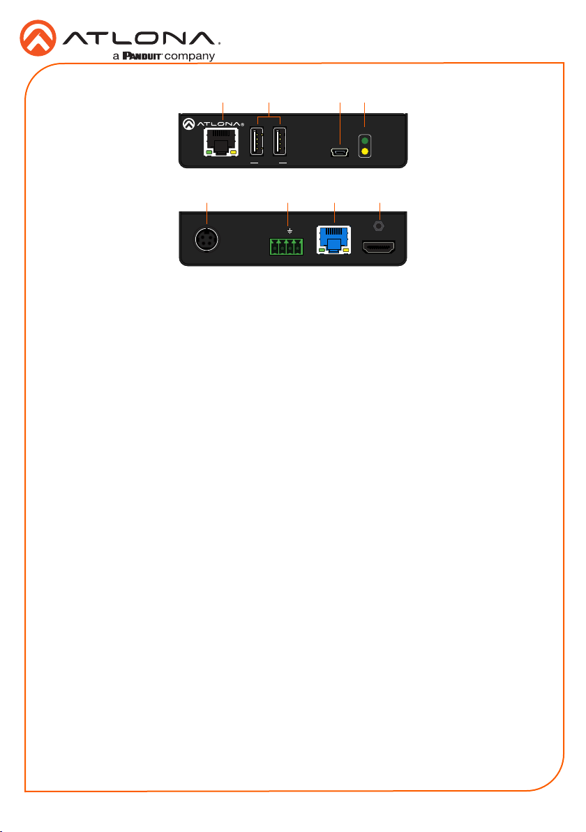
1. Connect a UHD/HD display to the HDMI OUT port.
2. Connect up to two USB devices (mouse, keyboard, etc.) to the DEVICE ports. These ports
provide 2.5 W per USB device.
3. Connect a category cable, from the HDBaseT IN port on the AT-OME-EX-RX, to the
HDBaseT OUT port on the transmitter.
4. OPTIONAL: Connect an Ethernet cable from the LAN port on the AT-OME-EX-RX, to the
display (sink) device. This cable provide IP pass-through transport control from a control
system to the display (sink) device connected to the AT-OME-EX-RX.
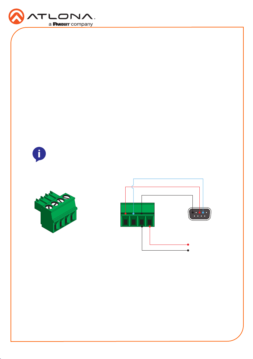
5. OPTIONAL: Connect the RS-232 device to the RS-232 port on the AT-OME-EX-RX.
Refer to RS-232 and IR (page 3) for more information.
6. OPTIONAL: Connect an IR emitter to the IR port on the transmitter. Connect an IR receiver
to the IR port on the AT-OME-EX-RX. Refer to RS-232 and IR (page 3) for more
information.
7. Connect the included 48 V DC power supply to the DC 48V power receptacle on the
transmitter.
8. Connect the power supply to an available AC outlet.
Refer to the tables below for recommended cabling when using Altona products with HDBaseT.
The green bars indicate the signal quality when using each type of cable. Higher-quality signals
are represented by more bars.
Core Shielding CAT5e CAT6 CAT6a CAT7
Solid UTP (unshielded) N/A
STP (shielded)
*Atlona recommends TIA/EIA 568-B termination for optimal performance.
Cable* Max. Distance @ 4K Max. Distance @ 1080p
CAT5e 295 feet (90 meters) 330 feet (100 meters)
CAT6 / CAT6a / CAT7 330 feet (100 meters) 330 feet (100 meters)
IMPORTANT: Stranded or patch cables are not recommended due to
performance issues.
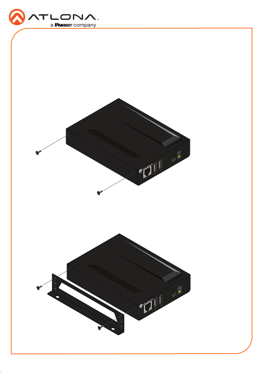
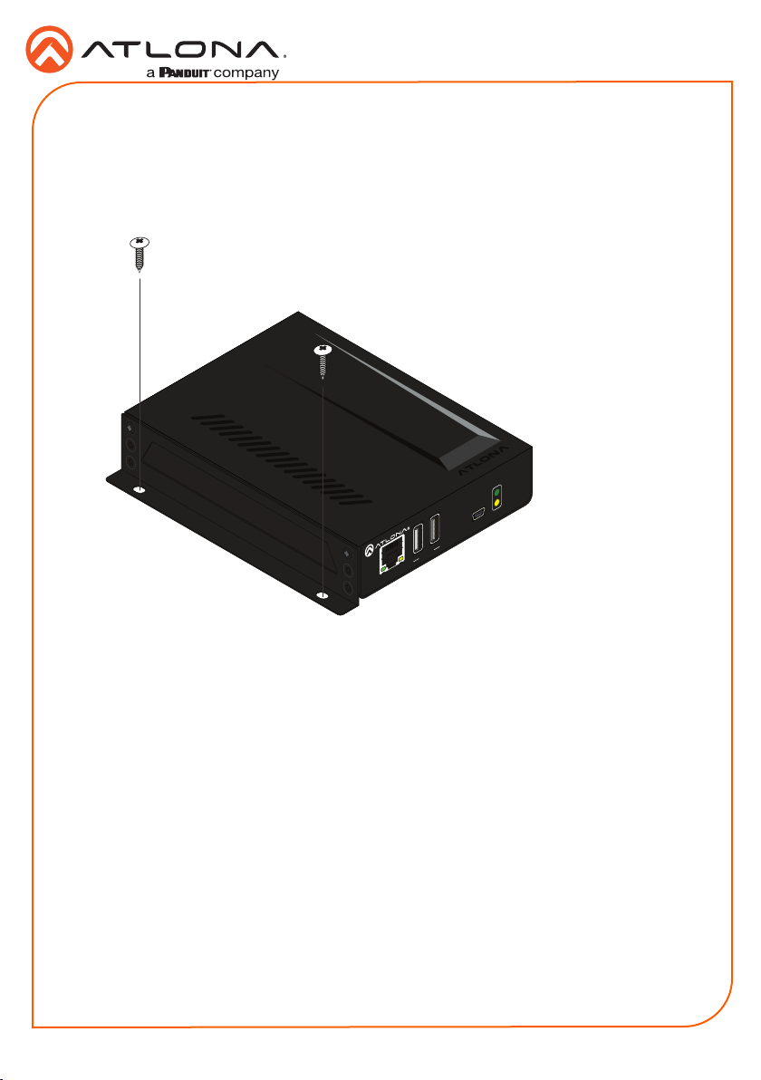
Installation
Cable Recommendation Guidelines