SR21 and OME Transmitters Setup 7
1. Connect the sources to the input ports on the OME-EX-TX and OME-SR21.
2. Connect an 568B terminated category cable to the HDBaseT output of the OME-EX-TX and the HDBaseT input
of the OME-SR21.
3. Connect an HDMI cable from the SR21’s HDMI output port to an HDMI display.
4. *Optional* Connect the 2CH analog AUDIO OUT ports to a DSP, or audio amplier.
a. Display control using the SR21 (preferred)- Connect an RS-232 cable from the display to port 1 of the
SR21. Commands will need to be programed using the webGUI but will be able to be triggered using webGUI
or RS-232/IP trigger commands:
DispBtn X. X= on, off, vol+, vol-, mute.
b. Display control using a control system - Connect an RS-232 cable from the control system to the OME
transmitter’s RS-232 port, using the rst three pins and an RS-232 cable from the display to port 1 of the SR21.
c. Source control - Connect an RS-232 cable from the OME transmitter to the source and connect a PC or
control system to the SR21 using RS-232 port 2 (the last three pins). Send commands using the RS232zone3[X]
command. X = source control command, found within the source’s manual.
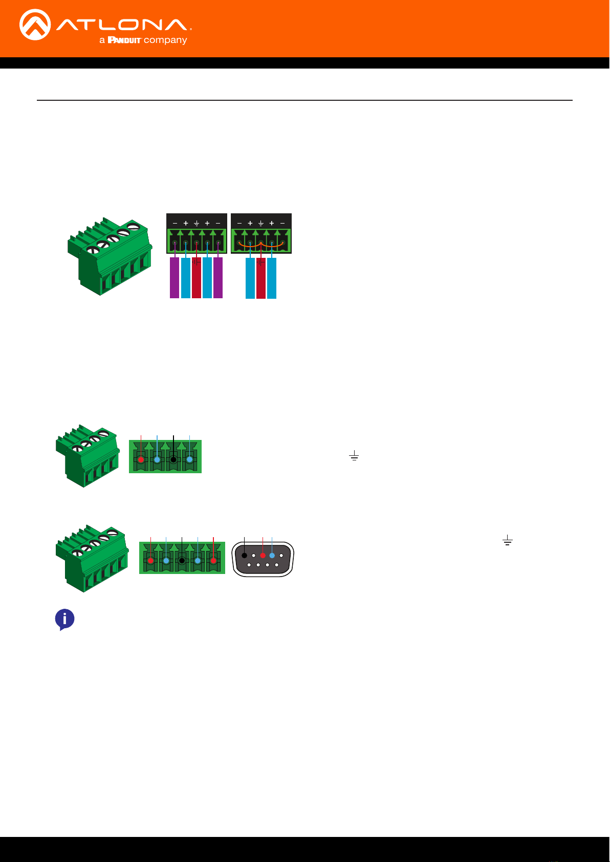
Use a jumper between the negative and ground pins
when using an unbalanced connection.
Balanced Unbalanced
Negative
-
Negative
-
+Positive
+Positive
Ground
+Positive
+Positive
Ground
5. *Optional* Connect USB devices (e.g. USB camera) to the USB hub ports on either the SR21 or OME transmitter.
6. *Optional* Connect the HOST USB port of either the SR21 or OME transmitter to a computer using a USB B to
USB A cable (cable not provided).
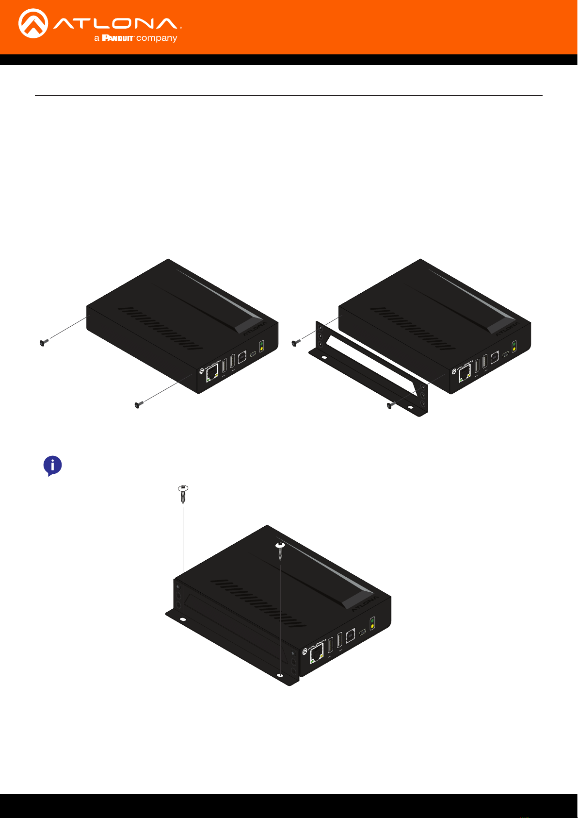
7. *Optional* For RS-232 control, captive screw connectors have been included. The OME-EX-TX will use a 4-pin
connector that only the rst three pins will be used. The OME-SR21 will use a 5-pin captive screw RS-232 port to
control the display (port 1) and the unit (port 2).
Connection
IR IN is not functional when using OME-EX-TX with SR21.
IR IN
RS-232
RS-232 Pin out will be determined by the RS-232 cable and connects as
RX (receive), TX (transmit) and (ground -shared with IR IN).
AT-OME-EX-TX
Pin out will be determined by the RS-232 cable and
connect as RX (receive), TX (transmit) and (Ground).
Ground will be shared between port 1 and port 2.
AT-OME-SR21
NOTE: The OME-EX-TX is a pass through device only, it will pass commands from a control system to
the SR21 or from the SR21 to a local source.
Port 1
Display Unit
Port 2