manuals.online logo
Brands
  1. Home
  2. •
  3. Brands
  4. •
  5. ParaBody
  6. •
  7. Home Gym
  8. •
  9. ParaBody 701 User manual

ParaBody 701 User manual

701
PARABODY 525 PEC DEC OPTION
PRODUCT ASSEMBLY
INSTRUCTIONS SHEETS
REV1SI:ON C
! ! ! ATTENTION! ! !
UNLESS__O_T_HER~
C_~NNE~
_CAg_NSJS_T~F ONE LD BO_L Z’~
~HERS, AND
ONE (,O_LO~K..N_U_T,_
BOLT.
701 FACTOR 525 PEC DEC ATT. ASSEMBLYPARTS LIST (LEVEL 1)
SORT AND COI.£NT ALL PARTS BEFOREBEGINNING ASSEMBLY
ITEM
2.
3.
4.
5.
6.
7.
g.
9.
I0.
If.
12.
13.
14.
NAME/DESCRIPTION QTY
I/2X4-I/2IN.BOLT............................................................................................................
2
3/8X2IN.BOLT..................................................................................................................
2
3/4IN.WASHER....................................................................................................................
2
I/2IN.WASHER....................................................................................................................
4
3/8IN.WASHER..................................................................................................................
4
I/2IN.LOCKNUT.....................................................................~.........................................
2
3/8IN.LOCKNUT................................................................................................................
COTTER.LESSHITCHPIN....................................................................................................
CABLERETAININGCLIP....................................................................................................
2
3/4I.D.STARLOCKCOLLAR.............................................................................................
3/4IN.FLANGEBEARING..................................................................................................
4
KNOB.....................................................................................................................................
2
CARRIAGEGUIDE...............................................................................................................
2
2IN.SQ.ENDCAP..............................................................................................................
6
WELDMENTS/PARTS:
ITEM NAME/DESCRIPTION QTY
2.
3.
4.
5.
6.
7
8.
BEARINGHOUSING....................................................
(6352701)..................................
CENTERPULLEYBRACKET...................................... (6352401).......................................
KIGHTPECDECAILM................................................. (6354101)....................................... l
LEFTPECDECARM.................................................... (6354201)....................................... 1
RIGHT ARM ADVANCE - .
.............................................. (63~210t’)....,.,..-.:.,<....:...:...:.............. 1
LEFTARMADVANCE................................................ (635-2-20-I-)....}:.,:.).~:.).’...:~.~..!.~::.:.......... 1
4X12ROLLERPAD..................................................... (6176201)....................................... 2
4-t/2XI IN.PULLEY............................................. :...(3116101)....................................... 2
NOTE: BOLT LENGTH IS MEASUREDFROM THE UNDERSIDE OF THE HEAD OFTHE BOLT.
I////i//l
BOLT LENGTH
BOLT LENGTH RULER:
I/2 [ I/2
23
701 FACTOR525 PEC DEC ATT. ASSEMBLY PARTS LIST (ZEVEL 2)
SORT AND COUNT ALL PARTS BEFORE BEGINNING ASSEMBLY
HARDWARE."
ITEM NAME/DESCRIPTION QTY
2.
3.
4.
5.
6.
7.
8.
9.
10.
II.
3/8X2IN.BOLT.................................................................................................................. 1
3/8Xi-314IN.BOLT............................................................................................................. I
3/8IN.WASHER....................................................................................................................
1/4IN.WASHER.................................................................................................................... 2
3/8IN.LOCKNUT................................................................................................................ 2
3/8IN.LOWHEIGHTLOCKNUT....................................................................................... 2
318IN.NUT............................................................................................................................ 2
t/4-25IN.NUT....................................................................................................................... 2
D-RINGCABLECLIP........................................................................................................... l
PULLEYBRACKET.............................................................................................................. l
SWIVEL.................................................................................................................................. l
WELDMENTS/PARTS:
ITEM NAME/DESCRIPTION QTY
2.
3.
4.
LINKCABLE................................................................. (6371801)....................................... 1
LOOPCABLE................................................................ (637I101).......................................
SHOCKCORD............................................................... (6271801).......................................
4-1/2X1IN.PULLEY................................................... (311610I)....................................... 3
NOTE: BOLT LENGTH IS MEASUREDFROM THE UNDERSIDE OF THE HEAD OF THE BOLT.
Iiiiiiii
BOLT LENGTIt
BOLT LENGTH RULER:
6
I._1
COTTERLE~HITCHPIN
LEFT PEC DEC
2 SO. END CAP (4) 0
RIGHTPEC DEC ARM
I~Y BRACKET
3/4 IN. WASHER (2)
LEFT ARMA[
RIGHT ARMAE
"-. ~~/-- .CAM STOP
CARRIAGE GUIDES (2)
1
// .//
~/~~i/2 X 4 I/2 IN BOLT (2)
~, ,
// 3/4 LD. STAR~OCK COL~ (2)
~2 SQ. END C~ (2) ~ ~ P~BODY I~C-
~ AS~ INST. 70
~01
NOTE:
I0.
FACTOR525 PEC DEC ATT. ASSEMBLYINSTRUCTIONS(LEVEL 1) ,--.
IF THE SHROUDIS ASSEMBLEDTO THE FACTOR525, IT WILL NEEDTO BE REMOVED
TO ASSEMBLETHE PEC DEC A’vrACHMENT. PLEASE REMOVETHE SHROUDAT TH][S
TIME BY CAREFULLYREMOVINGTIlE FOURTEEN(14) SHROUDFASTENERS.
Insert two (2) 2 IN. SQ. ENDCAPSinto both ends of the BEARINGHOUSING,as shown on drawing.
SECURELYassemble the BEARINGHOUSINGand the CENTERPULLEYBRACKETto the
FRONTUPRIGHTas shownon drawing, using two (2) I/2 X 4-I/2 IN. BOLTS,four (4) 1/2
WASHERS,and two (2) I/2 IN. LOCKNUTS. (THE CONNECTORPLATES ON THE BEARING
HOUSING AND THE CENTER PULLEY BRACKET HAVE SLOTTED HOLES. SHIFT THE
BEARING HOUSING DOWNAND THE CENTER PULLEY BRACKET UP AS FAR AS
POSSIBLE)
Insert four (4) 2 IN. SQ. ENDCAPSinto BOTHENDSof the LEFT, and RIGHTPECDECARMS
shown on drawing.
Assemble one (1) 314 IN: WASHER,and the LEFTARM.ADVANCEto the LEFT PECDECARM
shown on drawing. Also Assemble one (1) 3/4 IN. WASllEK,".,qd the RIGHTARMADVANCEto the~
RIGHT PEC DEC ARMas shown.
Insert four (4) 3/4 IN. FLANGEBEARINGSinto the BUSttlNGSof the BEARINGItOUSING,
shown on drawing.
Insert the LEFTand RIGHTPECDECARMSthrough the 3/,4 IN. FLANGEBEARINGSin the
BEARINGHOUSINGon their respective sides as shownon dr’awing, ~d SECUREthem in place with
two (2) 3/,4 I.D. STARLOCKCOL1.ARS.
Slide two (2) 4 X 12 ROLLERPADSonto the LEFTand RIGHTPEC DECARMS,until the
ROLLERPADis FLUSHwith the bottom of the ARMS.(IF A LUBRICANTIS REQUIRED,COAT
THE INSIDE OF THEROLI,ER PAl) WITll RUBIJINC ALCOIlOL. ALSO, ROTATINGTHE
PAD WHILE PUSHING UP WILL ilELP TO EASE ASSEMBLY)
Assemble two (2) KNOBSto two (2) COTTERLESSHITCHPINSas shown on drawing. Insert the
(2) COTTERLESSHITCHPINS through the BUSHINGSon th~ CAMSof the RIGHTand LEFTPEC
DECAR51S, and into the holes on the PEC ARMADVANCES.SEE DRAWING.
Attach two (2) CARRIAGEGUll)US ~o the CAB1STOPo,i the BEARINGltOUSINGwhere the
ARMADVANCESmakes contact with the CAMSTOP.
LOOSELYassemble two (2) 4-1/2 X I IN. PULLEYSand two (2~ CABLERETAININGCLIPS
CENTERPULLEYBRACKETas shown on dr-awing, using two (2) 3/8 X2 IN. BOLTS,four (,~) 13/8
WASHERS,and two (2) 3/8 IN. LOCKNUTS. (NOTE: THIS CONNECTIONWILL
TIGHTENEDAFTER TI4E CABLE I tAS BEEN ROUrED)
THIS CONCLUDES THE ASSFMBLY OF (LEVEL 1)
FACTOR525 PEC DEC ATT. ASSEMBLYINSTRUCTIONS (LEVEL 2) --.
LOOSENthe 3/8 X 4 IN. BOLTthat assembles the two (2) PULLEYS,and two (2) 1/2 IN. SPACEP,
the BASEdirectly behind the FRONTUPRIGHT.Removethe 3/$ IN. LOCKNUT,and the 3/g IN.
WASHER.Slide the BOLTout enough to remove the two (2) I/2 IN. SPACERS.Replace the 1/9- IN.
SPACERSwith one (1) 4-I/2. X1 IN. PULLEY,as shown in (VIEWB-B). Slide BOLTback
Replace the 3/8 IN. WASHER,and .3/8 IN. NUT. TIGHTENCONNECTIONSECURELY.
SECURELYassemble one (1) 4-1~ X 1 IN. PULLEYto the single hole in the BASEdirectly behind the
FRONTUPRIGHTas shownin (VIEWB-B) on drawing, using one (I) 3/8 XI-3/4 IN. BOLT,two
3/8 IN. WASHERS,and one (I)3/8 IN. LOCKNUT.
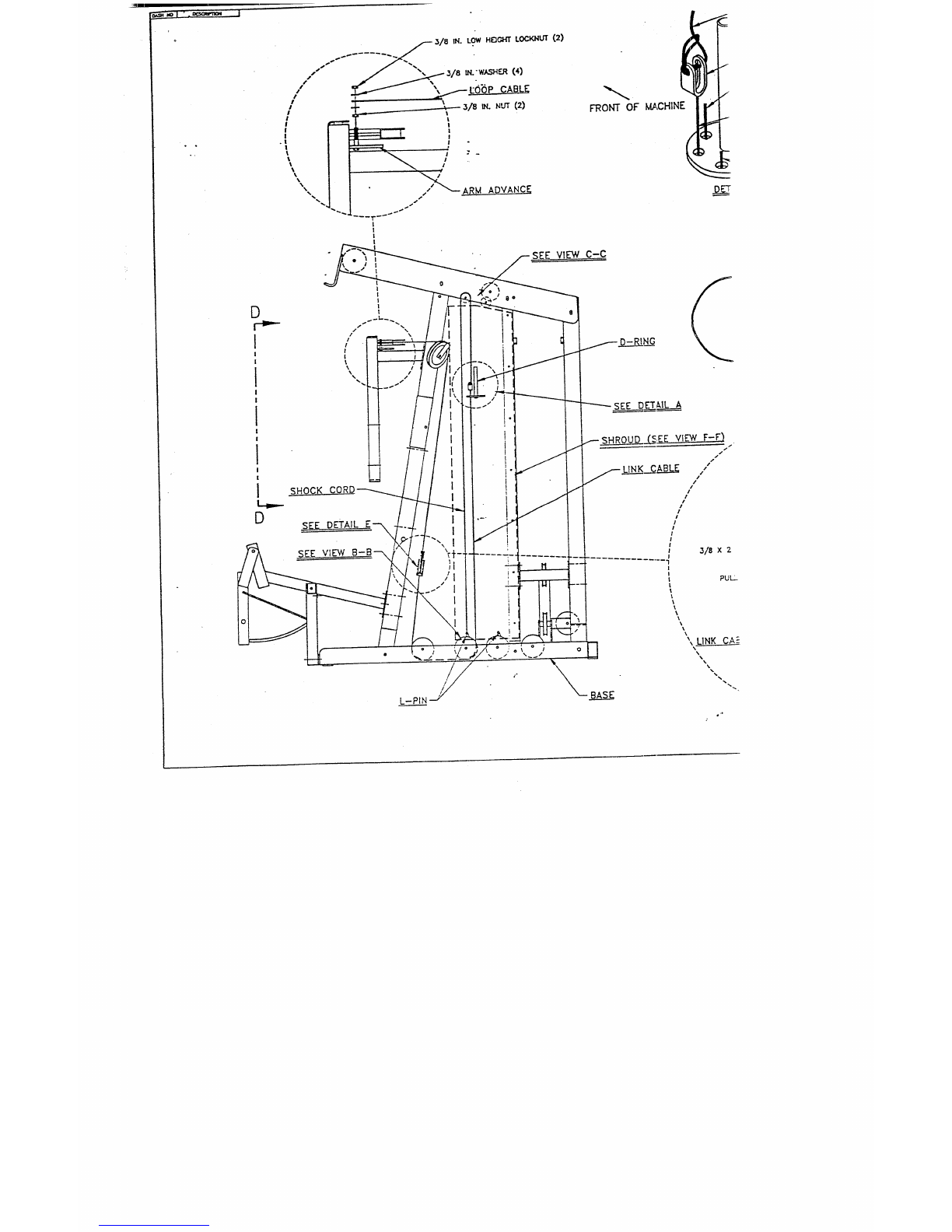
To assemble the LOOPCABLE,follow the cable routing diagram on drawing, and use the following
steps:
Assemble one end of the LOOPCABLEto the LEFTARMADVANCEand the other end ofthe
LOOP CABLE to the RIGHT ARMADVANCE(MAKE SURE THAT LOOP CABLE IS
ROUTED BETWEENTHE AB CRUNCHCABLE AND THE FRONT UPRIGHT) as shown
on drawing, using~.wo (2) 3/8 IN. NUT,four (4) 3/8 IN. WAS’HERS,and two (2) 3/8 IN.
HEIGItT LOCK NUT. (TIGHTEN THE CONNECTION ENOUGHTO REMOVETHE
PLAY, YET ALLOWING THE LOOP TO MOVEFREELY)
¯Drape the CABLEover the both PULLEYSon the CENTERPULLEYBR.kCKET. (THIS
WILL FORMA LOOP IN THE CENTER OF THE CABLE)
¯Position CABLERETAININGCLIPS in a 45 DEGREEposition over the PULLEYSand
CABLES,and tighten the two (2) PULLEYconnections SECURELY.SEE DRAWING.
To assemble the LINKCABLE,follow the cable routing diagram on drawing, and use the following steps:
¯LOOSELYassemble the PULLt"Y BRACKETto the LINK CABLEas shown in (DETAILE)
drawing, using two (2) I/4 IN. WASHER,and two (2) t/4-2S IN. NUTS.(LOCATEPULLEY
BRACKET HALF WAYUP ON TIlE THREADS OF THE LINK CABLE. DO NOT
TIGHTENNUTS AT TIllS TIME)
¯Slip one (I) 4-1/2 X I IN, PULLEYinto the LOOPofthe LOOPCABLEcreated from routing
STEP3. (VIEWD-D) While holding that PULLEYin the LOOP,SECURELYassemble the
PULLEYBRACKETover the PULLEYas show~l in (DETAILE) on drawing, using one (1) 3/~’,
2 IN. BOLT,two (2) 3;8 IN. WASI-IERS,and ot~e (I) 3~8 IN. LOCK
¯Route the LINKCABLEas shown on drawing. (ALSO SEE VIEWB-B)
¯Run the LINKCABLEthrough the pre-determined hole of:he D-RINGas shown in (DETAILA)
and attach one (1) D-RINGCABLECLIParound the ball end of the LINKCABLE.
Attach one (I) SHOCKCORDto the D-RINGCABLECLIP on the end ofthe LINKCABLEas shown
in (DETAILA).
Route tile SHOCKCORDup and around the prc-determined 2 IN. PULLEYabove the D-RINGas shown
in (VIEWC-C). and downto tile BASE.
Atmch one (l) SWIVELt° the end °fthe SHOCKCORD"Slipti:eendoftheSWIVEL°vertheL’P]N
on the BASE,and position the SWIVELdirectl: over the FIRSTPULLEYas shown in (VIEWB-B)
drawing.
701
NOTE:
lO.
FACTOR525 PEC DEC ATT. ASSEMBLYINSTRUCTIONS(LEVEL
The D-RINGCABLECLIPon the end of the LINKCABLEshould rcstjust above the D-RING.If the
LINKCABLEseemsto be pulling on the D-RINGor is resting too far above the D-RING,adjust it by
raising or lowering the two (2) 1/4-25 lN. NUTSthat attaches the LINKCABLEto the PULLEY
BRACKET.Whenthe correct height is obtained SECURELYtighten the two (2) 1/4-28 NUTStogether
around the PULLEYBRACKET.
To adjust the pre-stretch on the PECDECAILVIS:
Pull up on the COT’fERLESSHITCHPIN.
Swivel the ARMforward or backward.
Let the PIN drop downinto one ofthe two holes in the PECARMADVANCES.
Or let the PIN drop behind the PECARMADVANCES.
IF ASSEMBLING THE LEG PRESS ATTACHMENTNEXT, STOP HERE AND REFER TO
THOSE ASSEMBLY INSTRUCTIONS. IF ONLY ASSEMBLING TIIE PEC DEC ATTACHMENT
TO BASE UNIT, ~CONTINUE ON WITH THESE ASSEMBLYINSTRUCTIONS.
Wrapthe SHROUDaround the CABLESthat t-oute to the D-RING,and assemble the SHROUDto
BOTHSIDESof the MIDDLEU,’~PRIGHTas shown in (VIEWF-F) on drawing, using the fourteen (14)
SHROUD FASTENERS.
THIS CONCLUDESTHE ASSE~,IBLY OF (LEVEL 2), AND
THE ASSEMBLY OF THE PEC DEC ATTACHMENT FOR
THE FACTOR525 BASE UNIT.
D
SHOCKCC
SEED~I’AIL F--~
~EE VIEW C-C
o ;
L-PIN
FRONTOFI~,CHINE
SEE DET~,ILA
~SHROUD...C~.SEEVIEW F-F)
/
f LIN.__~K_~ABLZ /
i
!
~--D-RING CABL~ CtJP
~ LEG CURL/~ION
lAB CRUNCH CABLE
._A
r- D-R~NG
~$HROUI~FA_RI’ZNERS(I4.)
~o MIDDLEU PRIGF,’r
~~ SHROUD
VIEW F-F
FRONT OF MACHINE
o
VIEWB~B
FRONTOF MACHINE
DETAILC-C
VIEW D-D
FACTOR 525 PEC DEC~

Other manuals for 701

1

This manual suits for next models

1

Other ParaBody Home Gym manuals

ParaBody 350 User manual

ParaBody

ParaBody 350 User manual

ParaBody 911101 User manual

ParaBody

ParaBody 911101 User manual

ParaBody 887 User manual

ParaBody

ParaBody 887 User manual

ParaBody PBF508 User manual

ParaBody

ParaBody PBF508 User manual

ParaBody 359101 User manual

ParaBody

ParaBody 359101 User manual

ParaBody Serious Steel 400102 User manual

ParaBody

ParaBody Serious Steel 400102 User manual

ParaBody 909101 ST User manual

ParaBody

ParaBody 909101 ST User manual

ParaBody 828104 User manual

ParaBody

ParaBody 828104 User manual

ParaBody 950102 User manual

ParaBody

ParaBody 950102 User manual

ParaBody 220 User manual

ParaBody

ParaBody 220 User manual

ParaBody Serious Steel 425104 User manual

ParaBody

ParaBody Serious Steel 425104 User manual

ParaBody Parabody 805 User manual

ParaBody

ParaBody Parabody 805 User manual

ParaBody 40 User manual

ParaBody

ParaBody 40 User manual

ParaBody GS6 User manual

ParaBody

ParaBody GS6 User manual

ParaBody Free Standing Pec Dec 054 User manual

ParaBody

ParaBody Free Standing Pec Dec 054 User manual

ParaBody 920101 User manual

ParaBody

ParaBody 920101 User manual

ParaBody Parabody 660101 User manual

ParaBody

ParaBody Parabody 660101 User manual

ParaBody 426103 User manual

ParaBody

ParaBody 426103 User manual

ParaBody 225 User manual

ParaBody

ParaBody 225 User manual

ParaBody Serious Steel 425 User manual

ParaBody

ParaBody Serious Steel 425 User manual

ParaBody 893103 User manual

ParaBody

ParaBody 893103 User manual

ParaBody 435104 User manual

ParaBody

ParaBody 435104 User manual

ParaBody 462 User manual

ParaBody

ParaBody 462 User manual

ParaBody 913101 User manual

ParaBody

ParaBody 913101 User manual

Popular Home Gym manuals by other brands

Weider Pro 9730 user manual

Weider

Weider Pro 9730 user manual

Nautilus 2ST PULLOVER owner's manual

Nautilus

Nautilus 2ST PULLOVER owner's manual

Kettler Coach E Assembly instructions

Kettler

Kettler Coach E Assembly instructions

Merrithew Health & Fitness Vinyasa Triangle owner's manual

Merrithew Health & Fitness

Merrithew Health & Fitness Vinyasa Triangle owner's manual

ultega AB Trainer user manual

ultega

ultega AB Trainer user manual

Skandika STYRKE Assembly instructions and user guide

Skandika

Skandika STYRKE Assembly instructions and user guide

Weider Pro 240 user manual

Weider

Weider Pro 240 user manual

Abilica Magnetic Rower NS-RE6000 manual

Abilica

Abilica Magnetic Rower NS-RE6000 manual

Bowflex SelectTech BD55i Owner's manual and workout guide

Bowflex

Bowflex SelectTech BD55i Owner's manual and workout guide

Omega fitness CO-R130 Instruction book

Omega fitness

Omega fitness CO-R130 Instruction book

Taurus TF-B930 Assembly and operating instructions

Taurus

Taurus TF-B930 Assembly and operating instructions

Hoist Fitness 4600 Assembly instruction

Hoist Fitness

Hoist Fitness 4600 Assembly instruction

York Fitness 7245 LEG PRESS Assembly instructions

York Fitness

York Fitness 7245 LEG PRESS Assembly instructions

Weider Pro 495 user manual

Weider

Weider Pro 495 user manual

Impex MARCY PRO MD-5139 owner's manual

Impex

Impex MARCY PRO MD-5139 owner's manual

Impex ADI-5100-I owner's manual

Impex

Impex ADI-5100-I owner's manual

Image 8.0 Elliptical user manual

Image

Image 8.0 Elliptical user manual

Impex MARCY MWB 758 owner's manual

Impex

Impex MARCY MWB 758 owner's manual

manuals.online logo
manuals.online logoBrands
  • About & Mission
  • Contact us
  • Privacy Policy
  • Terms and Conditions

Copyright 2025 Manuals.Online. All Rights Reserved.