Paradise Datacom PH-6K-5 User manual

Page 1 of 28
PARADISE
HYDRAULIC BOATLIFTS
OWNERSHIP AND INSTALLATION MANUAL
2 CYLINDER HYDRAULIC MODELS MODELS
PH-6K-5
PH-6K-6
PH-8K-4
PH-8K-5
Part No. 100318 Rev. 1
Issued: 2021-06-08
Paradise Dock & Lift Inc.
4311A 25 Ave.
Vernon, BC, Canada
V1T 1P5
paradisedocklift.com
info@paradisedocklift.com
1-888-411-3625
PH-8K-5 SHOWN
COPYRIGHT © 2021 PARADISE DOCK & LIFT INC.
READ CAREFULLY PRIOR TO INSTALLATION AND
USE. RETAIN THIS DOCUMENTATION.

Page 2 of 28
Part No. 100318 Rev. 1
Issued: 2021-06-08
CONTENTS
Specications................................................. 2
Safety Information ....................................... 3
Liability Disclaimer....................................... 4
Component Overview ................................ 5
Assembly Instructions ................................ 6
Installation ...................................................... 22
Remote Control & Controller.................... 23
Maintenance .................................................. 24
Warranty .......................................................... 26
SPECIFICATIONS
Models and specications for Paradise hydraulic boatlifts covered in this manual are provided
in the table below:
*Custom bunk lengths and congurations are available
**Solar, and Lithium options available
Congratulations on acquiring your new
Paradise hydraulic boatlift system!
These lifts are built with the highest
quality 6061-T6 marine grade aluminum
and stainless steel hardware. All non-
adjustable components are welded to ensure
ease of installation. The stainless steel
cylinder and patented “retracted when up”
conguration ensures the maximum cylinder
life by preventing rod pitting/corrosion and
increasing seal life.
Our hydraulic uid is non-toxic and
biodegradable so you do not need to worry
about environmental harm. We hope you
enjoy your Paradise Hydraulic Boatlift!
Model
Factory Specications PH-6K-5 PH-6K-6 PH-8K-4 PH-8K-5
Rated Capacity 6000 lbs (2722 kg) 6000 lbs (2722 kg) 8000 lbs (3629 kg) 8000 lbs (3629 kg)
Cylinder Quantity 2 2 2 2
Lift Range 5 ft (1.52 m) 6 ft (1.83 m) 4 ft (1.22 m) 5 ft (1.52 m)
Approximate Weight 967 lbs (439 kg) 1022 lbs (464 kg) 969 lbs (440 kg) 993 lbs (450 kg)
Height Adjustment Range 82-118 in
(208-300 cm)
94-130 in
(239-330 cm)
0 in (0 cm) 82-118 in
(208-300 cm)
Frame Length (Raised) 180 in (457 cm)
Frame Width (Raised) 131-9/16 in (334 cm)
Bunk Length* 150 in (381 cm)
Power Supply** 24V-DC Deep Cycle Battery
Construction Welded 6061-T6 Aluminum
Pins 17-4PH Stainless Steel
Fasteners/Hardware 18-8 Stainless Steel

Page 3 of 28
Part No. 100318 Rev. 1
Issued: 2021-06-08
SAFETY INFORMATION
Always read and obey all safety messages and instructions when assembling, installing or
operating the boat lifting system. Boatlifts are heavy equipment that pose major hazards.
Your safety is of utmost importance so if there is any misunderstanding with information
contained in this manual, please contact your dealer or the manufacturer. Important safety
messaging will be outlined as follows:
DANGER! Failure to follow instructions WILL result in serious injury or death.
CAUTION! Failure to follow instructions CAN result in serious injury or death.
Failure to follow instructions/take appropriate actions COULD result
in serious injury, death, and/or property damage.
Note:
Paradise Dock & Lift Inc reserves the right to make changes to this product and manual at any
time without notice. This manual includes the latest information at the time it was printed and
the product was shipped. This manual should be kept available to whoever is using this product.
WARNING!
DANGER!
• Never allow any persons to go under or
on the lift particularly when it is operating
or supporting a load.
• All persons must stay clear of lift while the
lift is in operation.
• Never service a boatlift, boat or boatlift
accessory while the lift is supporting a
load.
• Your lift system is not intended to support
people, never actuate the lift with people
on-board. Unload and load passengers
only when the boat is oating and not
supported by the lift.
• Never exceed the lift’s rated capacity. The
gross/loaded weight of your watercraft
should always be less than the lift
capacity as indicated on the serial plate.
• Only operate the system to lift the
watercraft, do not use the system for any
other purposes or items.
• The lift should only be operated by adults.
Anyone who operates the lift must be fully
aware of the information outlined in this
manual.
• Do not play on or around the lift.
• It is not possible for the manufacturer to
identify all hazards surrounding the site
assembly, installation and operation of a
lift system. Owners, dealers, and installers
must use good judgement to assess risk,
and make installation, maintenance, and
operation decisions: Do not operate in
poor conditions, when system is not level,
or when noticeable corrosion/damage/
defects are present.
• Failure to properly position boat on lift
could make the lift unstable.
• Keep long hair, loose clothing, and jewelry
away from any moving parts.
CAUTION!
STAY CLEAR! DO NOT RIDE LIFT!

Page 4 of 28
Part No. 100318 Rev. 1
Issued: 2021-06-08
LIABILITY
DISCLAIMER
Installation and assembly instructions
provided are intended for authorized
Paradise Dock & Lift dealers and installers.
If you require assistance, please contact
Paradise Dock & Lift to be put in contact
with a dealer in your area who can safely
assemble and install this system. An installer
must determine if they have the necessary
experience, knowledge and skills to safely
assemble and install a lift system. If there is
any confusion, please contact Paradise Dock
& Lift. Improper assembly and/or installation
may cause a risk to property, safety or lift
functionality/reliability. A failure to correctly
follow assembly and installation instructions
constitutes a waiver of the installers rights
against Paradise Dock & Lift for subsequent
damages. The installation instructions
provided are not a warranty or guarantee,
best judgement must be used during
installation.
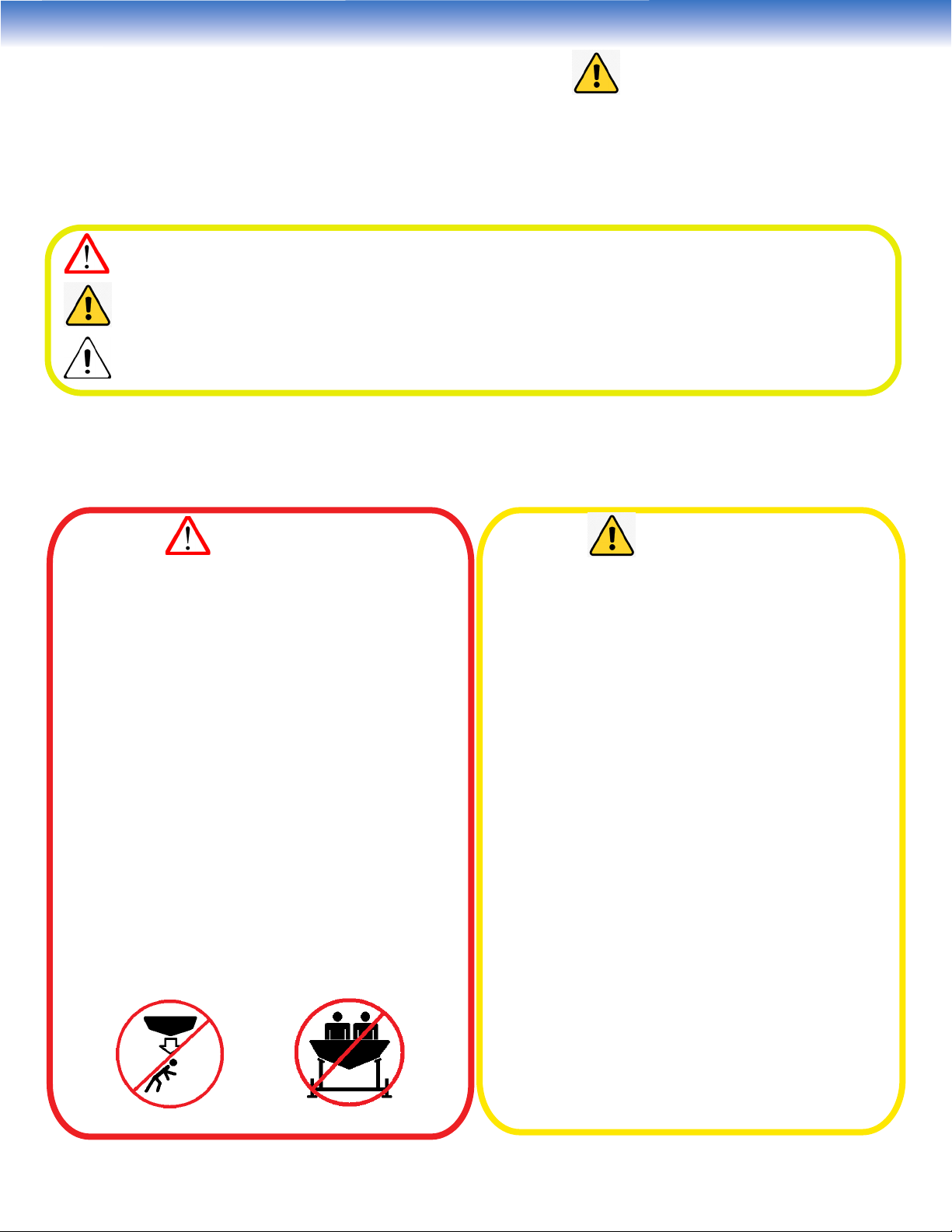
The standard Paradise hydraulic boatlift
bunk conguration is designed for
conventional v-hull boats. Many other
boat types (catamarans, pontoon, tritoon,
etc.) require custom supports and bunk
congurations. Any watercraft should
be supported as per boat manufacturer
recommendations and installers should
contact the boat manufacturer to verify.
Incorrect and inadequate support may
result in boat damage. Paradise Dock &
Lift can not determine, guarantee, warrant
or take responsibility for bunk/support
congurations meeting each manufacturers
recommendation.
CAUTION!
• During the rst few operations of the lift,
the weight of the watercraft may cause
the lift to settle. Stay well away from the
lift during actuation until it is seen that the
installation is stable.
• The frame structure, welds, bolt and pin
conditions should be inspected for issues
such as corrosion and wear annually.
• Do not store any items in the power pack
box. Items may damage hydraulic and
electrical systems.
WARNING!
• Leave the lift in the fully “up over centre”
position during storage, this is the safest
position.
• Do not position the lift near areas where
people swim or dive frequently. When it is
lowered, swimmers may inadvertently hit
the lift causing injury.
• It is recommended that the lift be
partially raised out of the water if people
are swimming in the vicinity. Use the
remote to raise the lift when departing so
swimmers can see the location of the boat
lift.
• Ensure that the lift remains level within 2
inches. Out-of-level lift installations may
be unstable and increases the risk of
capsizing and injury.
• Never disconnect hydraulic hoses with a
watercraft on the lift.
• Never enter the lift while the boat is under
power. Glide in at a slow speed. The lift is
not designed to take large impacts from
a fast moving boat. Large impacts may
cause damage to the lift.

Page 5 of 28
Part No. 100318 Rev. 1
Issued: 2021-06-08
Item Part Description Qty Part Number
PH-6K-5 PH-6K-6 PH-8K-4 PH-8K-5
1 Front H-Frame 1100067
2 Rear H-Frame 1100076
3Leg 4100091
4 Foot Pad 4100092
5 Side Beam 2100341 100051
6 Cross Beam 2100088
7 Hydraulic Cylinder 2100003
8 Bunk 2100086
9 Bunk Rubber 2100087
10 Guide-On (optional) 4100102
11 Extension Arm 4100070 100325 100430/
100431
100070
12 Cylinder Kit (includes hoses
and ttings) [not shown] 1-
13 Pump [not shown] 1-
14 Power Pack (includes box
and pump) [not shown] 1-
COMPONENT OVERVIEW
2 Cylinder Hydraulic Boatlift Models
10
1
2
11
3
5
9
8
7
4
6
Direction of boat
entry

Page 6 of 28
Part No. 100318 Rev. 1
Issued: 2021-06-08
Tools Required:
• 9/16”Wrench, socket and ratchet
• 3/4”Wrench, socket and ratchet
• 7/32” Allen Key
• Needle Nose Pliers
• Torque Wrench (20-60 ft lbs range)
• Hand drill and 7/8” drill bit
• Lacquer torque seal or paint marker
• Anti Seize
ASSEMBLY INSTRUCTIONS
WARNING! - Follow all assembly instructions, failure to assemble lift as
described may lead to warranty issues, hazards, or the lift misfunctioning.
Step 1 - Assemble H-Frames (Items 1 & 2)
Hardware Required:
• 8x 1/2”-13 - 4” Long Hex Bolts
• 8x 1/2”-13 - 4.5” Long Hex Bolts
• 8x 1/2”-13 - 5” Long Hex Bolts (PH-8K-4)
• 16x 1/2”-13 - Kep Nuts
• 32x 1/2” - Flat Washers
Note: Apply Anti-Seize to ALL Stainless Steel Bolts
• Marine Grease
• Rubber mallet
• Tape Measure
• Pencil/Pen
Using the 3/4” wrenches:
1-A) Assemble the Rear H-Frame. Bolt on the
inner cross tube using the 4”long bolts:
1-B) Bolt on the leg extension (item 11) using
the 4.5” long bolts. Use the top set of bolt holes
on the leg extension for the Rear H-Frame:

Page 7 of 28
Part No. 100318 Rev. 1
Issued: 2021-06-08
1-F) Torque the bolted connections to 56 ft-lbs and mark the nuts as torqued with the torque seal/
paint marker.
1-G) If the model PH-8K-4 boatlift is being assembled, bolt on the bunk attachment plates
(P/N 100430 and 100431) as shown using 5” long bolts and torque the bolts per Step 1-F. (see
illustration on next page):
1-C) Complete one side of an H-Frame:
(Rear H-Frame shown)
1-D) Repeat steps A-B for the other side:
(Rear H-Frame shown)
1-E) Repeat Steps A-D for the Front H-Frame assembly. Use the bottom set of bolt holes on the leg
extensions (item 11) in order to raise the top of the leg extensions by 2.5”. This ensures a raised
pitch of the bunks.
Top bolt hole on leg
extension is exposed on
the Front H-Frame
Leg Extension
(Item 11)
Bolt holes for
Front H-Frame
Bolt holes for
Rear H-Frame
WARNING! - Failure to bolt leg extensions as described in Step 1 will cause
improper operation of the boatlift.

Page 8 of 28
Part No. 100318 Rev. 1
Issued: 2021-06-08
2-A) Assemble the 4 legs and 4 foot pads:
2-B) Bolt the legs to the foot pads using the 9/16”wrenches (remember to apply anti-seize):
Step 2 - Assemble the Legs (Item 3) and Foot Pads
(Item 4)
Hardware Required:
• 4x 3/8”-16 - 3.75” Long Hex Bolts
• 4x 3/8”-16 - Kep Nuts
• 8x 3/8” - Flat Washers
P/N 100430 x4 P/N 100431 x4
Rear H-Frame Front H-Frame

Page 9 of 28
Part No. 100318 Rev. 1
Issued: 2021-06-08
Step 3 - Assemble the Cross Beams (Item 6) and
Legs (Item 3)
Hardware Required:
• 4x 3/8”-16 - 4.5” Long Hex Bolts
• 8x 1/2”-13 - 4.5” Long Hex Bolts
• 4x 3/8”-16 - Kep Nuts
• 8x 1/2”-13 - Kep Nuts
• 8x 3/8” - Flat Washers
• 16x 1/2” - Flat Washers
3-A) Assemble the 2 cross beams on the 4 legs. Set the height of the cross beams such that the
top of the cross beams remain 24 inches below the water surface at the lowest water depth of the
installation location (See the Installation section of this manual for further details):
2-C) Torque the bolted connection to 23 ft-lbs.

Page 10 of 28
Part No. 100318 Rev. 1
Issued: 2021-06-08
3-C) Torque the 3/8-16 bolted connection to 23 ft-lbs and the 1/2-13 bolted connection to 56
ft-lbs.
Step 4 - Assemble the Side Beams (Item 5) on the
Cross Beams (Item 6)
Hardware Required:
• 8x 3/8”-16 - 4.5” Long Hex Bolts
• 8x 3/8”-16 - Kep Nuts
• 16x 3/8” - Flat Washers
4-A) Use a tape measure and pencil to mark the approximate location of the side beams as
indicated below. These locations can be adjusted to suit the bunk spacing necessary to support
the watercraft:
3-B) Apply anti-seize to the bolts prior to installation. Bolt the cross beams and legs together (3/8-
16 bolts and 9/16” wrench for the legs, 1/2-13 bolts and 3/4”wrench for the cross beams):

Page 11 of 28
Part No. 100318 Rev. 1
Issued: 2021-06-08
4-B) Assemble the Side Beams on to the 2 cross beams:
4-C) Use the 9/16” wrenches and hardware to loosely bolt and clamp the side beams to the
cross beams:

Page 12 of 28
Part No. 100318 Rev. 1
Issued: 2021-06-08
Step 5 - Attach H-Frames (Item 1 & 2) to Side
Beams (Item 5)
Hardware Required:
• 4x 3/8”-16 - 3/4” Long Button Head Screws
• 4x 3/8” Lock Washers
• 4x Lower Pin Assemblies (P/N 100081)
5-A) Grease pin assemblies.
5-B) Use the pin assemblies to attach the H-Frames (item 1 & 2) to the side beams (item 5).
5-C) Use the button head screws and 7/32” Allen key to secure the pin assemblies to the H-Frame
assembly and ensure the pin does not slide out.
Front H-Frame
(Item 1)
Rear H-Frame
(Item 2)

Page 13 of 28
Part No. 100318 Rev. 1
Issued: 2021-06-08
Step 6 - Assemble Cylinders
Hardware Required:
• 4x 3/8”-16 - 3/4” Long Button Head Screws
• 4x 3/8” Lock Washers
• 4x Pin Assemblies (2x P/N 100077, 2x P/N
100180)
• 4x Lower Pin Assemblies (P/N 100081)
• 8x Plastic Washers (P/N 100276)
5-D) Tighten the hardware from step 4-C now that the H-Frames are attached. Torque the 3/8 bolts
to 23 ft-lbs.

Page 14 of 28
Part No. 100318 Rev. 1
Issued: 2021-06-08
6-A) Use the pin assemblies to attach the hydraulic cylinders (item 7) to the rear H-Frame (item 2).
Use the plastic washers to space the cylinders from inside face of the aluminum lugs:
6-B) Apply marine grease to the pins. Secure the pins using the 7/32” Allen key to tighten the 3/8”
button head screws:
P/N 100180
P/N 100077

Page 15 of 28
Part No. 100318 Rev. 1
Issued: 2021-06-08
Step 7 - Install Bunks (Item 8)
Hardware Required:
• 4x 1” Diameter Bunk Pins
• 4x Cotter Pins - 1/8”x 2”
• 4x 1” Flat Washers
• 8x 1” Plastic Washers (P/N 100276)
7-A) Place bunks (item 8) on H-Frame assemblies:

Page 16 of 28
Part No. 100318 Rev. 1
Issued: 2021-06-08
7-B) Install bunk pins to secure bunks to H-Frame. Use plastic washers on the inside surfaces of the
bunk as spacers. Use cotter pins and at washer to secure bunk pins. Bend the end of the cotter
pin with the needle nose pliers to secure the pins.
Step 8 - Install Guide-Ons (Item 10) (Optional)
Hardware Required:
• 8x 3/8”-16 - 6” Long Hex Bolts
• 4x 3/8”-16 - 4” Long Hex Bolts
• 12x 3/8”-16 - Kep Nuts
• 24x 3/8” - Flat Washers

Page 17 of 28
Part No. 100318 Rev. 1
Issued: 2021-06-08
8-A) Assemble guide-on bracket and arm and lift into position:
WARNING!
Note the correct locations indicated above by the check marks, incorrect
installation can cause damage to the lift frame and/or bunks.
X
X
X
X
8-B) Bolt guide-ons to bunk using 3/8-16 x 6” long bolts. Apply anti seize, tighten the bolts with
9/16” wrench and torque to 23 ft-lbs.

Page 18 of 28
Part No. 100318 Rev. 1
Issued: 2021-06-08
8-C) Bolt the adjustable arm into place using the 3/8-16 x 4” long bolts. Apply anti seize, tighten
the bolts with 9/16” wrench and torque to 23 ft-lbs. Position the arms such that they t the boat
width with a minimum 2 inch spacing on each side of the boat. Place the plastic pipe and guide-on
covers over the guide-on tube. The guide-ons are adjustable to dierent boat widths.
9-A) Mount plastic hose clips to the inside of side beams using #8 self-tapping screws as shown in
the image below. A third clip is included in the hardware kit to facilitate hose routing and can be
mounted to the dock or anywhere required. Ziptie the hoses as shown and route the hoses under
the side beam to the power pack box.
Step 9 - Route Hoses to Cylinders
Hardware Required:
• 2x Plastic Hose Clip (P/N 100030)
• 4x #8 Self-tapping Screws

Page 19 of 28
Part No. 100318 Rev. 1
Issued: 2021-06-08
9-B) Ensure that a minimum of 20”length of hose is between the top of the clip to the bottom
tting of the cylinder as indicated by the two arrows. This length is the minimum required for the
hoses to not bind when the lift actuates.
Step 10 - Connect Power Pack
10-A) Connect quick-connect hydraulic ttings to power pack. Use a 3/4” wrench to hold the tting
and 1-1/4” wrench to tighten the quick connect.
Note: If quick-connects are dicult to connect, relieve some pressure by pressing the male end on
a hard surface. Use eye protection when doing this and be cautious not to damage the tting.

Page 20 of 28
Part No. 100318 Rev. 1
Issued: 2021-06-08
10-B) Check tightness of the battery terminals. If the battery terminal nuts are not tight, turn
the nuts one at a time until hand tight and then 1/2 turn using a wrench.
Step 11 - Install Solar Panels on the Power Pack
(Optional)
11-A) To install the solar panels to the power pack, rst locate the orientation of the solar panel
on the lid of the power pack as shown below. Mark the location of the solar panel black electrical
connection on the lid of the power pack (approx. 3 inches from edge of lid) and use a 7/8” drill bit
to drill a 7/8” hole in the lid. Insert the solar panel electrical wire into the power pack. Secure the
solar panel to the lid of the power pack using double-sided tape.
This manual suits for next models
3
Table of contents
Popular Marine Equipment manuals by other brands

Raymarine
Raymarine RayPilot 650 Professional System Upgrade instructions

CBE
CBE Concorde PC770-SK Technical documentation

Kasco
Kasco CertiSafe Assembly & installation manual

Citadel
Citadel AF300 PRO installation instructions

Garmin
Garmin GHP Reactor Hydraulic installation instructions

JRC
JRC JHS-180 instruction manual