manuals.online logo
Brands
  1. Home
  2. •
  3. Brands
  4. •
  5. Paradise Datacom
  6. •
  7. Outdoor Light
  8. •
  9. Paradise Datacom 280957 Installation manual

Paradise Datacom 280957 Installation manual

3 HEAD DELUXE STREETLIGHT
RÉVERBÈRE DE LUXE À TROIS TÊTES
FAROL DE CARRETERA DE 3 LÁMPARAS
INSTALLATION, CARE AND USE INSTRUCTIONS
INSTRUCTIONS D’INSTALLATION, DE SOIN ET D’UTILISATION
INSTRUCCIONES DE INSTALACIÓN, CUIDADO Y UTILIZACIÓN
Questions, problems, missing parts?
For assistance with assembly or installation, parts and customer service, call:
1-888-867-6095 (English), Monday to Friday 9a.m. to 5p.m. - PST, North America.
Questions, problèmes, pièces manquantes?
Pour toute assistance avec le montage, l’installation, les pièces et le service à la clientèle,
composez le : 1-888-926-2111 (français), du lundi au vendredi de 9 heures à 17 heures - EST,
Amérique du Nord.
Preguntas, problemas, piezas faltantes?
Para ayuda con la instalación o montaje, piezas y servicio al cliente, llame al:
1-888-867-6095 (Inglés), del lunes al viernes de 9 a 17 - PST, América del norte.
IMPORTANT, RETAIN FOR FUTURE REFERENCE: READ CAREFULLY
IMPORTANT, CONSERVER POUR RÉFÉRENCE : LIRE ATTENTIVEMENT
IMPORTANTE, CONSERVE PARA REFERENCIA FUTURA: LEA CUIDADOSAMENTE
ITM. / ART. 280957
5006-280957-TRI_011619
246 cm
96.85 in / po
79.4 cm
31.26 in / po
Imported by:
Costco Wholesale U.K. Ltd /Costco
Online UK Ltd
Hartspring Lane
Watford, Herts
WD25 8JS
United Kingdom
01923 213113
www.costco.co.uk
Distributed by:
Costco Wholesale Iceland ehf.
Kauptún 3-7, 210 Gardabaer
Iceland
www.costco.is
Distribué par :
Costco France
1, avenue de Bréhat
91140 Villebon-sur-Yvette (France)
www.costco.fr
ABCDEFGHIJKL
MN O
YZAA
PQRS
AB AC AD AE
TUVWX
AF AG AH AI
1. Before you begin
• Decide on an appropriate location for your streetlight (see site instructions).
• An assistant will be required during the installation of this product.
• The installation of the underground power cable and conduit must meet national and local standards. The illustrations showing the conduit and cable installed are only to use as a guide. The type and
depth of the conduit and cable may vary from area to area. It is recommended to consult a qualified electrician for the installation of the underground power cable and conduit.
• IMPORTANT: Always switch off the electricity supply at the mains during installation and maintenance. We recommend that the fuse is withdrawn or circuit breaker switched off at the
distribution board while work is in progress (turning off the light switch is not sufficient).
• If you are in any doubt about installing this product, please consult a qualified electrician.
2. Site Instructions
2.1 The lamp post must be mounted on a flat, stable surface. The chosen location must allow the post to be securely mounted using suitable fixings (not supplied), or set into concrete using
the anchors supplied (see below).
2.2 The streetlight must not be subject to immersion. The post must not be put into ponds or pools of water or mounted where an accumulation of water will occur.
2.3 Do not allow foliage to grow in proximity of the lamp.
3. Preparation
MAKE CERTAIN:
3.1 To disconnect power at the main fuse/breaker box before installing the fixture.
3.2 The ground wire is not connected to current carrying supply wires.
3.3 No bare wires are exposed outside of connectors when connecting current-carrying fixture wires to current-carrying house wires.
3.4 The insulation on fixture wires has not been damaged during installation.
3.5 No rough or sharp edges from any surfaces are in contact with wires.
3.6 Fixture supply wires are connected to proper house supply wires.
3.7 To use light bulbs with wattage no greater than specified for the fixture (MAX 100W, A60 Bulb type).
3.8 Power is off when placing light bulbs in fixture.
CONNECTIONS: ALL ELECTRICAL CONNECTIONS MUST BE IN ACCORDANCE WITH LOCAL CODES, ORDINANCES OR THE NATIONAL
ELECTRICAL CODE. IF YOU ARE UNFAMILIAR WITH METHODS OF INSTALLATION OF ELECTRICAL WIRING, PLEASE CONTACT A LOCAL
LICENSED ELECTRICIAN.
4. Assembly and Installation Instruction
CONCRETE BASE ASSEMBLY:
Note: The depth of this base will depend on local soil conditions and winter frost depth. The concrete base should be a minimum of
36 cm (14 3/16”) in diameter in order to hold the anchor bolts and the triangle plate.
4.1 Mix and pour the concrete into the base until it reaches the top.
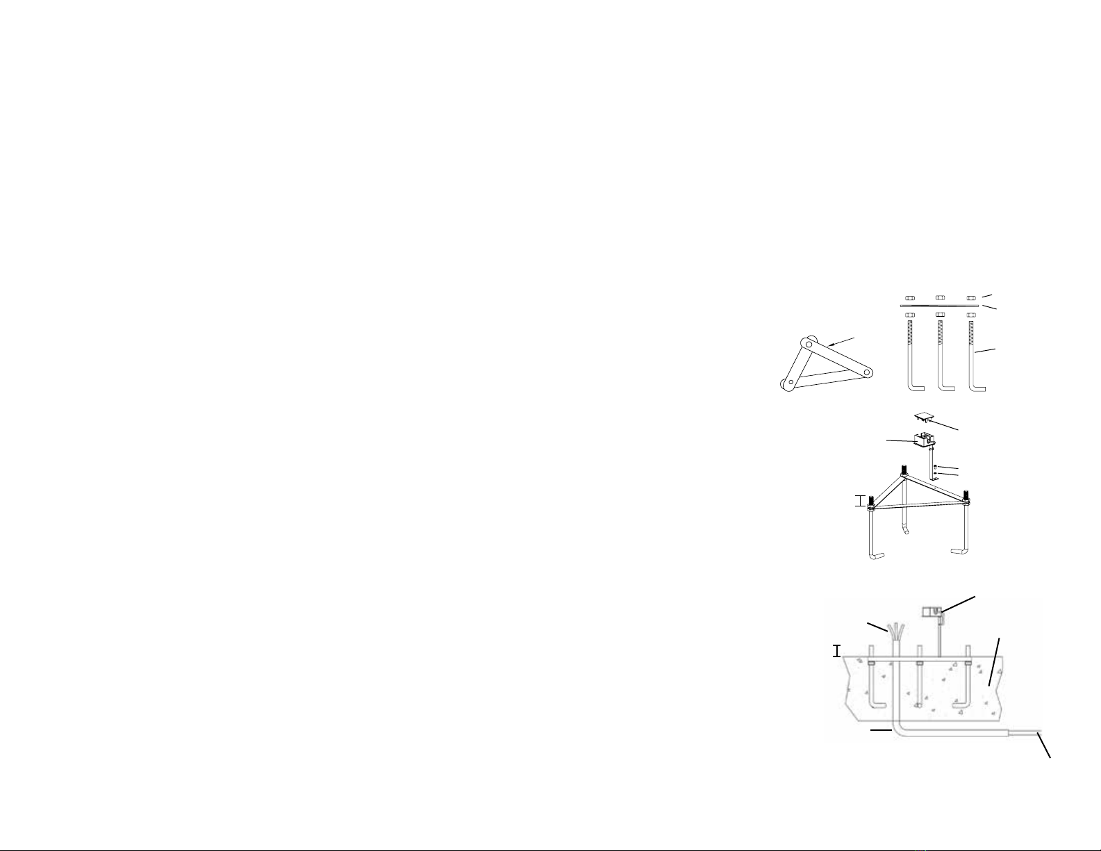
4.2 Add one (1) nut (AF) to each anchor bolt (P), insert them into the plate (M) and add one (1) nut (AF) to each bolt (P). Leave
20 mm (0.79”) of thread sticking out above the top of the nut.
4.3 Attach the lower terminal connector (N) to the plate (M) with a M4X8mm screw (V) and spring washer (AB), then place the lower
terminal connector’s cover (O). The position of the triangle plate (M) will also determine the orientation of the streetlight. To
determine the triangle plate (M) position assemble post and mark the triangle’s position.
4.4 Push the triangle assembly into the concrete until the top of the triangle is flush with the concrete top. Gently tap the side of the
base to make sure the anchor bolts are fully surrounded by the concrete. Make sure that the top of the concrete base, the top of
the triangle plate (M) and the bolts (P) are all level and that the bolts stick out 20 mm (0.79 in.). At this point, make sure that you
have installed the conduit (not included and usually required by local code) and allow 1.22 m (48 in.) of the line voltage cable to
extend from the concrete base.
4.5
Once the concrete has settled and dried, remove the top nut (AF) from anchor bolts in order to allow the bottom of the streetlight to
rest flat on the concrete base
.
ABCDEFGHIJKL
MN O
YZAA
PQRS
AB AC AD AE
TUVWX
AF AG AH AI
ABCDEFGHIJKL
MN O
YZAA
PQRS
AB AC AD AE
TUVWX
AF AG AH AI
2
PLATE (M)
PLATE (M)
6 NUTS (AF)
3 ANCHOR
BOLTS (P)
M4X8mm (V)
M4 (AB)
20 mm
(0.79’’)
* Leave at least 1.22 m
(48 in.) of cable to be able to
connect the wire properly.
LINE VOLTAGE CABLE
LINE VOLTAGE CABLE *
CONDUIT
CONCRETE BASE
LOWER TERMINAL CONNECTOR (N)
LOWER TERMINAL
CONNECTOR (N)
LOWER TERMINAL
CONNECTOR
COVER (O)
20 mm
(0.79’’)
Step 4.2
Step 4.3
Step 4.4
5. Wiring and assembly
5.1 Pre-assemble the covers (C) to the arms (D) using the four (4) M4x12 mm (T) screws and teeth washers (Z) (Fig. 3).
5.2 Pre-assemble the arms (D) to the spreader section (H) by passing the wire exiting each arm through the holes in the spreader. Join all
three (3) arm wires and connect to the main streetlight cable using the terminal connectors. (Fig. 4) NOTE: Make sure to connect the
live (L), neutral, (N) and ground (G) wires to the terminal block.
5.3 Connect one end of the main cable (AI) to the terminal block inside the spreader(H). (Fig. 1) NOTE: Make sure to connect the live
(L), neutral, (N) and ground (G) wires to the terminal block.
5.4 Attach each arm to the spreader with the two (2) M6x25 mm screws (S) and teeth washer (Z) using a 5 mm hex key (AH)
(included). Use exterior caulking to seal around the perimeter (not included). (Fig. 4)
5.5 Pre-Assemble finial (F) and washer (G) on top post cap (E). (Fig. 1)
5.6 Attach the post cap (E) on top of the spreader with the three (3) M5x10 mm (W) set screws using the 2.5 mm hex key (AG)
(included). (Fig. 1)
5.7 Attach the top post (I), bottom post (I) and spreader (H) by screwing them together in a clockwise direction and securing them with
M5x6 mm (X) set screws using 2.5 mm hex key (AG) (included). Also make sure to feed the main cable(AI) from the spreader down to
the post sections. (Fig. 4)
5.8 Assemble the top base (K) and the bottom base (L) with the three (3) M8x30 mm (Q) screws and teeth washers (Y) using
a 14 mm wrench (not included). Feed the main cable (AI) from the post sections to the base. (Fig. 2)
5.9 Remove the terminal box cover (O) from the lower terminal box (N) which is fixed on the anchor plate. Connect the line voltage
cable to the terminal block inside the terminal box. Connect the main cable (AI) through the base to the terminal block.
Cover back the terminal box cover. (Fig. 2) NOTE: Make sure to connect the live (L), neutral, (N) and ground (G) wires to the
terminal block.
5.10 Mount the base onto the three (3) anchor bolts (P). Secure the base with the three (3) spring washers (AC) and three (3)
cap nuts (AE) provided. (Fig. 2) Attach the flange (J) to the base with the three (3) M6x14 mm (R) screws and teeth washers (Z)
using a 12 mm wrench (not included)
5.11 Raise the top part of the streetlight and place it on the assembled base. Rotate the top part to line up
the holes. Secure with the three (3) M6 x 14 mm screws (R) and teeth washers (Z) with a 5 mm
hex key (AH) (included). At this point you may require an assistant. (Fig. 5) Caution: This part is heavy.
5.12 Install the light bulbs, 100 watt maximum each (not included).
5.13 Attach the bottom covers (B) to the lamp bodies
(A) using four
(4) M4x10mm screws (U) and teeth
washers(AA). (Fig. 3)
5.14 Secure the lamp bodies (A) to the cover (C)
using the 6 thumbscrews (AD). (Fig. 3)
3
Caution: Be careful- Handle glass with
care to avoid breakage or injury.
ABCDEFGHIJKL
MN O
YZAA
PQRS
AB AC AD AE
TUVWX
AF AG AH AI
M5 X 10 mm (W)
POST CAP (E)
FINIAL (F)
WASHER (G)
Fig. 1
Fig. 3
ABCDEFGHIJKL
MN O
YZAA
PQRS
AB AC AD AE
TUVWX
AF AG AH AI
M5 X 10 SET SCREWS (W)
SPREADER (H)
M5x6 (X)
M5x6 (X)
TOP POST (I)
BOTTOM POST (I)
FLANGE (J)
POST CAP (E)
FINIAL (F)
WASHER (G)
Fig. 4
ABCDEFGHIJKL
MN O
YZAA
PQRS
AB AC AD AE
TUVWX
AF AG AH AI
* MIN. 1.22 m (48 in.)
OF CABLE REQUIRED
Fig. 2
TOP BASE (K)
BOTTOM BASE (L)
CONCRETE BASE
ANCHOR
BOLTS (P)
CAP NUTS (AE)
M8 X 30 SCREWS (Q)
TEETH WASHERS (Y)
SPRING WASHERS (AC)
LOWER TERMINAL
BLOCK (N)
MAIN CABLE (AI)
ABCDEFGHIJKL
MN O
YZAA
PQRS
AB AC AD AE
TUVWX
AF AG AH AI
M4 X 12 SCREWS (T)
M6 X 25 mm (S)
WASHERS (Z)
M4 X 10 THUMBSCREWS (U)
TEETH WASHERS (AA)
COVER (C)
TEETH WASHERS (AA)
LAMP BODY (A)
BOTTOM COVER (B)
ARM (D)
THUMBSCREWS (AD)
MAIN CABLE (AI)
TEETH WASHERS (Z)
M6 X 14 SCREWS (R)
M6 X 14 SCREWS (R)
TEETH WASHERS (Z)
ABCDEFGHIJKL
MN O
YZAA
PQRS
AB AC AD AE
TUVWX
AF AG AH AI
Fig. 5
4
6. Test Installation
Restore the main power supply and turn the light switch to the ON position.
7. Troubleshooting
If the bulbs do not light:
7.1 Check that the main power supply (main fuse/breaker box) is turned on.
7.2 Check that the light switch is turned on.
7.3 Ensure that the bulbs are not defective.
8. Maintenance
• To clean, wash with a damp soft cloth.
• To replace the bulbs, reverse procedures 5.13 and 5.14 of the wiring and assembly section.
• Replacement parts may be ordered by using the fixture model number and the part’s name.
FIVE-YEAR (5-YEAR) LIMITED WARRANTY
This product, excluding electronic and/or electrical parts (if applicable), is guaranteed to be free from defects in material and workmanship for five (5) years. The fixture’s finish is guaranteed against peeling for
two (2) years. The electronic and electrical parts are guaranteed against defects for one (1) year. Should a defect occur, please contact our customer service at the following email address: customerservice@
sternohome.com. A proof of purchase (sales receipt) is required. If we cannot replace the defective part you require, you can return your product to the original point of purchase for a full refund or a
replacement product. The consumer is responsible for the removal and reinstallation of the product. Damage to any parts as such by accident, misuse, or improper installation is NOT covered by this warranty.
Our policy does not include liability for incidental or consequential damages. Some states or provinces do not allow the exclusion or limitation of consequential damages; therefore, the above exclusion may not
apply to you. This warranty gives you specific legal rights and you may also have other rights that vary from place to place.

Other Paradise Datacom Outdoor Light manuals

Paradise Datacom GL22612 User manual

Paradise Datacom

Paradise Datacom GL22612 User manual

Paradise Datacom GL22915 User manual

Paradise Datacom

Paradise Datacom GL22915 User manual

Paradise Datacom GL22724 User manual

Paradise Datacom

Paradise Datacom GL22724 User manual

Paradise Datacom U000-0880 User manual

Paradise Datacom

Paradise Datacom U000-0880 User manual

Paradise Datacom GL28637SS User manual

Paradise Datacom

Paradise Datacom GL28637SS User manual

Paradise Datacom GL22315 User manual

Paradise Datacom

Paradise Datacom GL22315 User manual

Paradise Datacom GL33872 User manual

Paradise Datacom

Paradise Datacom GL33872 User manual

Paradise Datacom GL22977 User manual

Paradise Datacom

Paradise Datacom GL22977 User manual

Paradise Datacom GL281006 User manual

Paradise Datacom

Paradise Datacom GL281006 User manual

Paradise Datacom GL33210 User manual

Paradise Datacom

Paradise Datacom GL33210 User manual

Paradise Datacom GL28649 User manual

Paradise Datacom

Paradise Datacom GL28649 User manual

Paradise Datacom M45944848 User manual

Paradise Datacom

Paradise Datacom M45944848 User manual

Paradise Datacom GL29829 User manual

Paradise Datacom

Paradise Datacom GL29829 User manual

Paradise Datacom GL22921 User manual

Paradise Datacom

Paradise Datacom GL22921 User manual

Paradise Datacom U000-1712 User manual

Paradise Datacom

Paradise Datacom U000-1712 User manual

Paradise Datacom GL39065 User manual

Paradise Datacom

Paradise Datacom GL39065 User manual

Paradise Datacom U000-1848 User manual

Paradise Datacom

Paradise Datacom U000-1848 User manual

Paradise Datacom GL22785 User manual

Paradise Datacom

Paradise Datacom GL22785 User manual

Paradise Datacom GL23974 User manual

Paradise Datacom

Paradise Datacom GL23974 User manual

Paradise Datacom GL33458 User manual

Paradise Datacom

Paradise Datacom GL33458 User manual

Paradise Datacom GL29353 User manual

Paradise Datacom

Paradise Datacom GL29353 User manual

Paradise Datacom U000-0780 User manual

Paradise Datacom

Paradise Datacom U000-0780 User manual

Paradise Datacom GL23922 User manual

Paradise Datacom

Paradise Datacom GL23922 User manual

Paradise Datacom GL33683 User manual

Paradise Datacom

Paradise Datacom GL33683 User manual

Popular Outdoor Light manuals by other brands

Philips 69069/**/16 user manual

Philips

Philips 69069/**/16 user manual

MOOD LIV Installation Notice

MOOD

MOOD LIV Installation Notice

ROBENS THACLA TIPI LAMP instruction manual

ROBENS

ROBENS THACLA TIPI LAMP instruction manual

Landscape Forms Motive installation guide

Landscape Forms

Landscape Forms Motive installation guide

Digitus DN-16101 manual

Digitus

Digitus DN-16101 manual

Philips 163384716 user manual

Philips

Philips 163384716 user manual

V-TAC VT-ST15 instruction manual

V-TAC

V-TAC VT-ST15 instruction manual

Lighting Technologies FREGAT LED manual

Lighting Technologies

Lighting Technologies FREGAT LED manual

WAF One-Light quick start guide

WAF

WAF One-Light quick start guide

SLV CUBIX QPAR51 instruction manual

SLV

SLV CUBIX QPAR51 instruction manual

Philips AmazonLED2 BBC201 Mounting instructions

Philips

Philips AmazonLED2 BBC201 Mounting instructions

BEMKO LOP1-030BL-4K instructions

BEMKO

BEMKO LOP1-030BL-4K instructions

MAXSA 43319 Assembly and Instruction Guide

MAXSA

MAXSA 43319 Assembly and Instruction Guide

LIGMAN MV-30052 installation manual

LIGMAN

LIGMAN MV-30052 installation manual

Bailey Compact GX53 quick start guide

Bailey

Bailey Compact GX53 quick start guide

LIGMAN COLUMBUS 3 instruction manual

LIGMAN

LIGMAN COLUMBUS 3 instruction manual

Satco NUVO LIGHTING 65-064 Installation and service instructions

Satco

Satco NUVO LIGHTING 65-064 Installation and service instructions

LIGMAN UTAH 4 installation manual

LIGMAN

LIGMAN UTAH 4 installation manual

manuals.online logo
manuals.online logoBrands
  • About & Mission
  • Contact us
  • Privacy Policy
  • Terms and Conditions

Copyright 2025 Manuals.Online. All Rights Reserved.