Paragon GZ3584-1 User manual

7’
9’4’’
13’1’’
10’8’’
12’3’’
9’9’’
Gazebo GZ3584-1
Aluminum Composite Roof Panels
Assembly Instructions
Paragon Group USA

Introduction
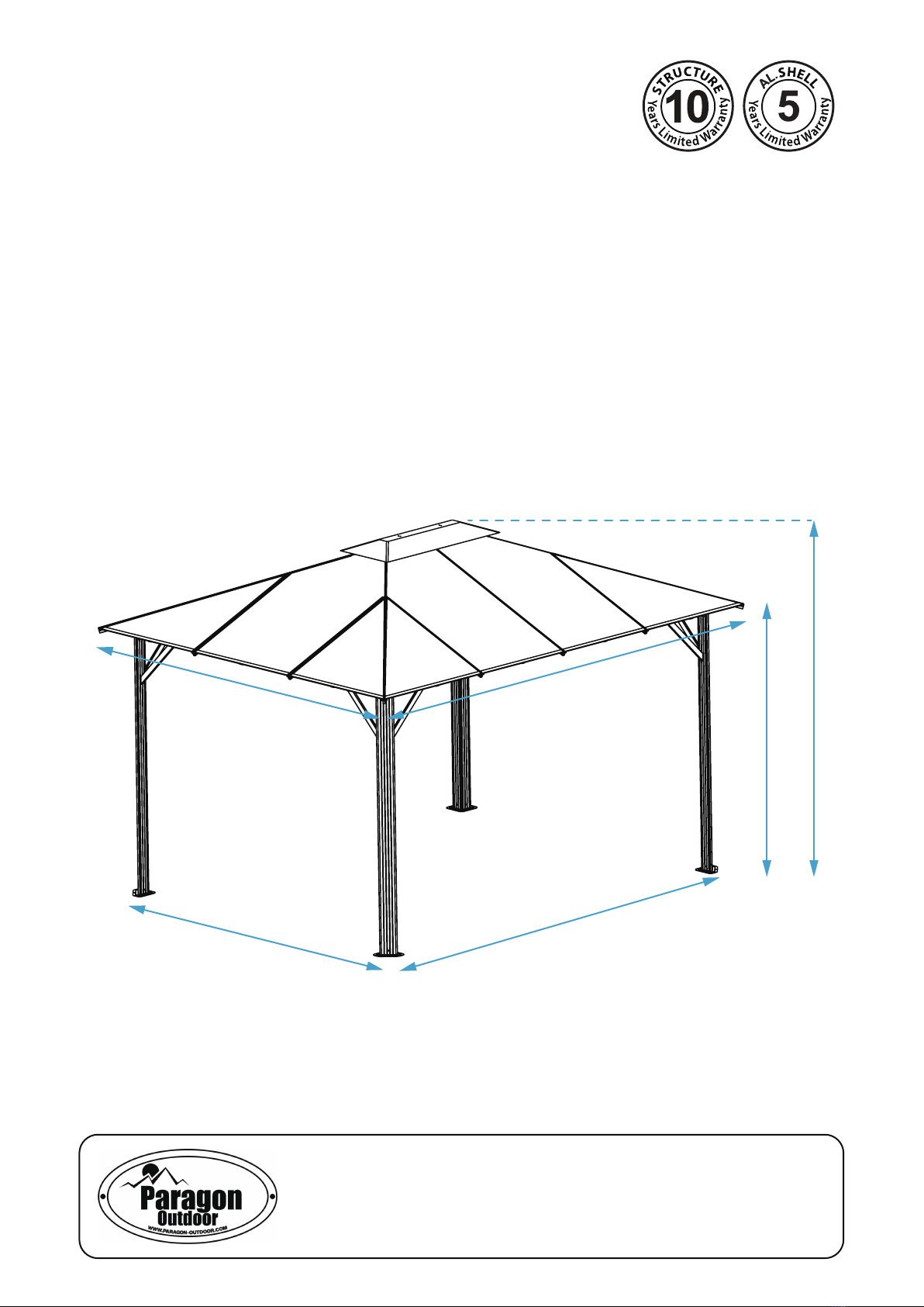
Thank you for purchasing the Gazebo GZ3584-1.
When properly assembled and maintained, this gazebo will provide many years of enjoyment!
These instructions include helpful hints and important information needed to safely assemble and properly
maintain the gazebo. Please read these instructions completely before you begin.
Our patented gazebo has been designed for easy assembly. All steps can be completed by a team of
four people. The assembly should take about two hours.
Before Starting Assembly:
CAREFULLY READ ALL THE INSTRUCTIONS BEFORE YOU BEGIN AND FOLLOW THE
STEPS IN THE ORDER THEY ARE PRESENTED.
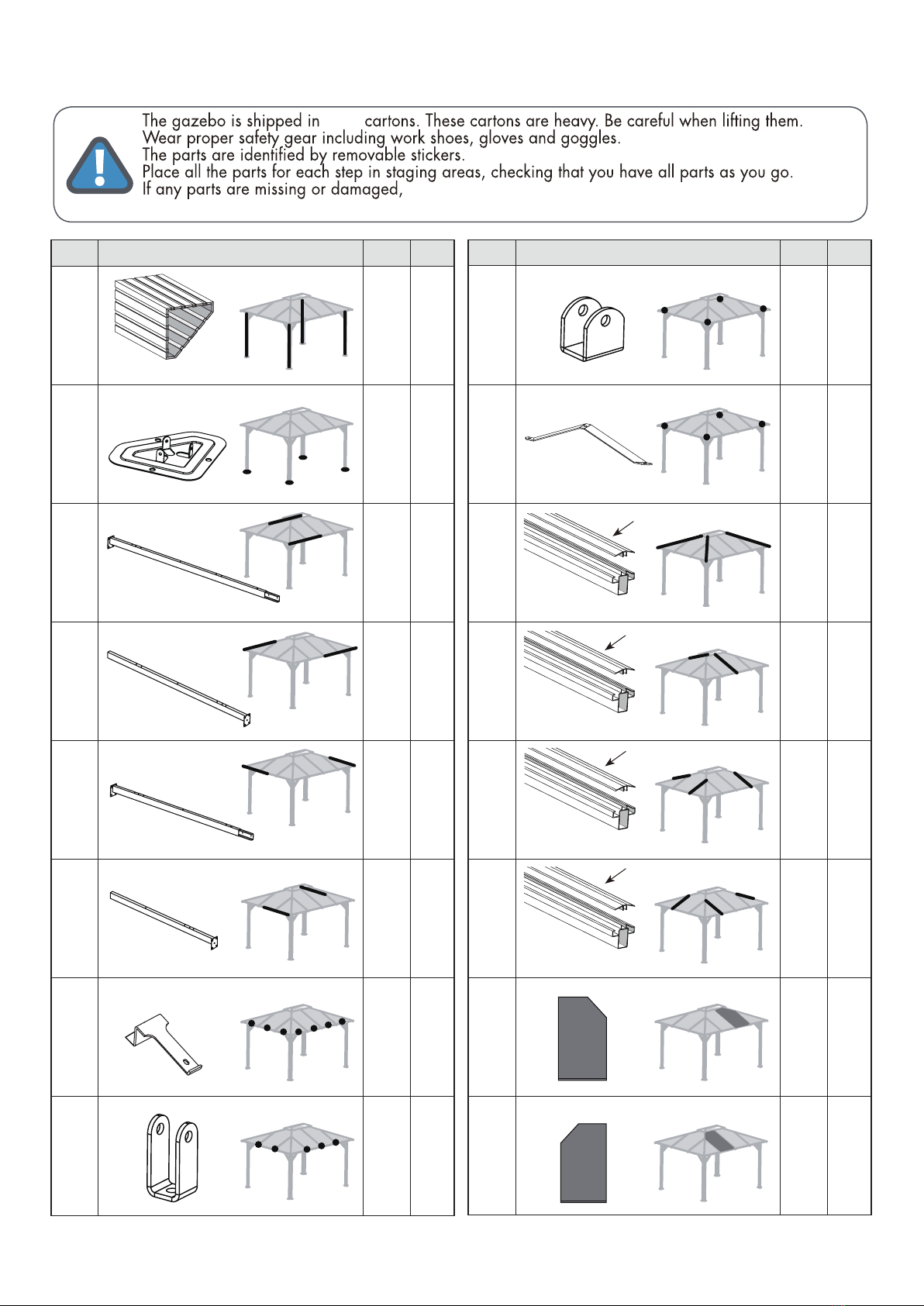
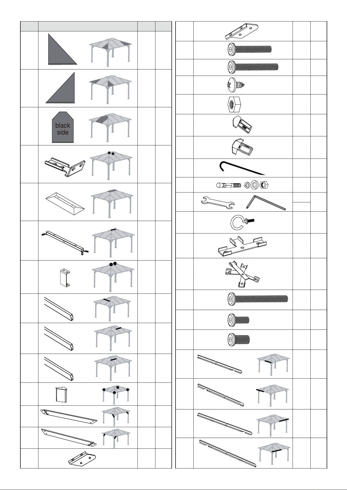
1.Make sure you have all the necessary parts:
Compare the contents of all cartons to the List of Parts. If any parts are missing ordamaged, or
you have any questions, please contact Customer service: (877)782 4482before beginning assembly.
2.Lay the parts out inseparate staging areas:
The List of Parts has the corresponding step number referenced to each part. We recommend that
while you go through the list, make staging areas for each step and place the parts necessary for
each step in these areas. Thiswill save you time and effort during assembly.
3.Select a Location:
When selecting a location for your gazebo, a flat level area is essential and if possible with proper
water drainage andeasy access to power and water, if neccessary.
Choose a sunny, levelpositionaway from overhanging trees and power linesand protected from the
wind as much as possible. Locate underground pipes or cables before preparing the site or anchoring
the gazebo.
Note: You may assemble the gazebo on a hard level surface and move it to its final location when
finished. Make sure that there are no obstacles between the assembly area and the finalposition.
4. Prepare a Foundation:
After choosinga location, proper preparationof the site is recommended. The site must be level.
If the site is not level, create a base slightly larger than theoutside dimensions of the gazebo using a
perimeter of two by fours filled with either soil, sod or gravel.
Make sure the base is square by measuring the diagonals from both directions and making sure
they are equal. The gazebo is secured with pegs into holes cast with concrete.
If you decide to have a concrete base, it is best to contact a reliable contractor to make sure it is flat
and level. Make sure you have checked with your local authorities regarding any required building
permits.
5. Make sure you have the proper tools:
• Tape Measure • 2 Small Step Ladders
• Work Gloves • Wooden Mallet
• Safety goggles • Scissors and knife
• Phillips Screwdriver • Liquid soap or WD40 Lubricant
• Spirit Level
NOTE: A cordless drill with Phillips head bit is highly recommended but not essential.
2 of 24

of 243

of 244
List of Parts
1978mm
1629mm
1639mm
No. Part Qty Step
1 4
1
2 4
1
3 2
2
4 2
2
5 2
2
6 2
2
7 14
4
8 10
4
No. Part Qty Step
9 4
4
10 4
4
11 4
6
12 2
6
4
6
14 4
6
15 2
8
16 2
8
2200mm
1228mm
11A
2092mm
2346mm
12A
1530mm
1696mm
13A
1154mm
14A
1154mm
1164mm
1164mm
13
black
side
black
side
Customer Service:(877) 782 4482 Email:[email protected]
three
contact customer service before beginning assembly:

of 245
31 4
4
48 2
4
49 2
4
50 2
51 2
4
37 10
9
38 4
9
39 12
5
40 12
5
41 1
42 1
7
43 2
6
44 4
6
46 164
No. Part Qty
Step
17 4
8
18 4
8
19 2
8
20 2
6
21 1
6
22 1
6
23 2
6
24 2
7
25 2
7
26 2
7
27 4
1
28 4
4
29 4
4
30 4
4
We included some extra screws and bolts for your convenience.
1
black
side
black
side
32 66
45 2
47 32
34 14
35 16
33 4
M6*15mm
M6*38mm
M6*45mm
M6*55mm
M8*15mm
M4*8mm
M6
4
1,2,4
6,7
6
6
6
3
8
6
1419mm
1419mm
1754mm
1754mm

of 246
x 4
x 4
Corner profile (1)
x 4 Corner profile
cover (27)
x 4
Support plate (2)
x 4
Screw (46)
x 12
1
1 1 1 1
1
1
2
2 2 2 2
2
27
46
46
46
1.A
1.B 1.C
Place all the parts on a level surface.
Make sure the pieces are in the correct positions before assembling.
Carefully follow the order of assembly to ensure an easy installation.
Wear proper safety gear including work shoes, gloves and goggles.
Place corner profiles (1) parallel to each other
on the ground. Slide support plates (2) into
corner profiles from the end with a single
screw hole, as shown.
Fasten each plate to profile using
three screws (46).
Insert corner covers (27)
into top ends of corner profiles (1)
as shown.
STEP 1
Components
x 4
Assembling the Corner Profiles

of 247
2121212121
5
5
2121212121
5
2121212121
5
2121212121
5
5
5
2121212121
5
2121212121
5
Roof profile (5)
x 2
Roof profile (6)
x 2
2.A
2.B
Place all the parts on a level surface. Make sure the pieces are in the correct positions
before assembling. Carefully follow the order of assembly to ensure an easy installation.
Wear proper safety gear including work shoes, gloves and goggles.
STEP 2
Components
Roof profile (3)
x 2
Roof profile (4)
x 2 Screw (46)
x 8
3
4
6
4
4
46
46
3
5
56
3
x 2
x 2
Assembling the Roof Profiles
Insert end of short roof profile (5) into short roof profile (6) as shown. Fasten with screws (46).
Repeat to make two sets.
Insert end of long roof profile (3)
into long roof profile (4) as shown.
Fasten with screws (46).
Repeat to make two sets.

of 248
Screw (47)
x 32
Components
ILLUSTRATION
3
4
3.A
3.B
Attach long roof profile
sets (3,4) to corner profiles (1) as shown.
Fasten with screws (47).
Repeat to make two sets.
Attach short roof profile sets (5,6) to corner profiles (1)
as shown.
Fasten with screws (47).
47
47
47
27
1
1
1
1
1
1
1
1
1
1
6
6
6
5
5
3
3
3
4
4
STEP 3
4
Attaching Roof Profiles to
Corner Profiles

3
4
3
4
6
5
5
6
49
48
48
49
10 46
46
8
46
8
46
46
8
46
8
46
8
46
8
46
8
46
8
46
8
46
8
46
46 46
46
10
10
10
46 46
50
51
51
50
of 249
46
46
10
10
46
48/50
49/51
8
46
48/49
50/51
3/4/5/6
8
46
51
50
34
Components
Upper roof (50)
x 2
Upper roof (51)
x 2
Upper roof (49)
x 2
Upper roof (48)
x 2
STEP 4
Screw(46)
x 98
U connector (8)
x10
U connector (9)
x4
Roof connector (7)
x14
Roof corner
connector (10)
x4
4.A
VIEWS FROM
OUTSIDE GAZEBO
4/6
Support connector
(30)
x4
Support bar
(28)
x4
Support bar (29)
x4
Support connector
(31)
x4
3/5
Attaching the Upper Roof Profiles and Roof
Connectors to Roof and Corner Profiles
Attach upper roof profiles (48,49,50,51) to roof profiles(3,4,5,6)as shown.
Overlap profiles in middle of each gazebo side to form one single screw hole.
Fasten with screws (46), attaching U connectors (8) at same time, as shown.
Slide ends of parts (10) through slits in profiles (48,49,50,51) from inside gazebo and fasten
with screws (46).
CROSS
SECTION
VIEW FROM
OUTSIDE GAZEBO
3/5
48/51
ATTENTION: One side of the U Connector (8) has a
reinforcement bar, which should be facing the inside of the
gazebo.The side without the bar should be facing out when
installingon profiles(48,49,50,51).

of 2410
4.B
4.C
Attach U connectors (9) to top of corner
posts (1), as shown, using screws (46).
VIEW FROM INSIDE
GAZEBO
VIEW FROM
OUTSIDE GAZEBO
9
1
46
Attach two roof connectors (7) to each upper roof profile set (48,49) and (50,51) as shown
(facing outwards).Fasten with two screws (46) each.
7
46
48/49
50/51
3/4/5/6
46
9
46
9
46
9
46
9
48
49
48
49
51
50
50
51
46
7
46
7
46
7
46
7
46
746
746
7
46
746
746
7
46
7
46
7
46
7
46
7

of 2411
IMPORTANT : After this step you should place the gazebo frame in its desired location.
Make sure all corners are squared at 90 degrees.
4.D
Attach one support connector (30) and one support connector (31) to each corner post (1)
at pre-drilled screw holes, using two screws (46) each.
Slide support bars (28) onto support connectors (31) and fasten with two screws (46).
Attach upper end of support bars (28) to roof profiles (4,6), fasten with two screws (46).
Slide support bars (29) onto support connectors (30) and fasten with two screws (46).
Attach upper end of support bars (29) to roof profiles (3,5), fasten with two screws (46).
VIEW FROM INSIDE
GAZEBO
VIEW FROM INSIDE
GAZEBO
VIEW FROM INSIDE
GAZEBO
1
1 1
46
46 46
46 46
30
28
30
2928
3/5
4/6 4/6
28
29
29
29
29
28
28
28
3
4
3
4
6
5
5
6

of 2412
Components
Concrete screws, washers and nuts
(40)
x 12
Wood Screws, washers x 12
NOT SUPPLIED
to be purchased by user
1. 2. 3.
Optional
Concrete Floor:
1.Using an electric concrete drill, drill holes into the concrete floor,
corresponding to the holes in the support plates.
2.Insert concrete screws (40) into the holes and hammer into place, using a mallet.
3. Fasten concrete screws with washers and nuts.
Wood Deck:
1.Using an electric wood drill,drill holes into the wood floor,
corresponding to the holes in the support plates.
2.
Insert wood screws with washers (not supplied) into the holes and fasten,
using an electric screw driver.
Securing the Gazebo to the Ground
STEP 5
Components
39
39
39
1
2
5.A
Fasten the gazebo frame to the ground, using three spikes (39)
for each support plate.
Ground spike (39)
x 12
Securing the Gazebo to a Concrete Floor
or Wood Deck

of 2413
Installing the Low Roof GableProfiles
STEP 6
Components
Roof Top
Cover(21)
x 1
X-connector (44)
x 4
Screw(46)
x 34
Screw(32)
x 14
Screw(33)
x 4
Nut M6(35)
x 16
Roof Gable
Profile(12)
1696mm
x 2
Roof Gable
Profile(11)
2346mm
x 4
U-shaped
Connector(23)
x 2
T-connector A(43)
x 2
Roof Gable
Profile(13)
1164mm
x 4
Roof Gable
Profile(14)
1164mm
x 4
Roof Top
Connector Beam(22)
x 1
Top center
connector(20)
x 2
Screw(45)
x 2
Roof Profiles,roof panels
and gables must be aligned
properly during assembly
to minimize any possibility
of leaking.
12
14 13
13 14
13 14
14 13
12
2. 3.
1. 1.
3.
3.
3.
3.
3.
2. 3.
1. 1.
3.
Using at least three people, install the roof gables (11,12,13,14) in the following order :
2346mm
1696mm
11 12 13 14

14 of 24
32 35
46
Install roof gable profiles (12).
Using screws (45) nuts (35) connect top center connector (20) to top connector beam(22).
Using screws (32) nuts (35) connect profiles (12) to inner roof connector (8) on long roof profiles sets
(3,4) and the other end to roof top center connector(20).
46
20
20
35 22
45
20 12
46
6.A
1
32 9
11
1
10
46
11
9
12
8
32
6.B
35
11
11
11
11
22
12
12
22
35

15 of 24
46
46 46
33 33
33
33
46
43
46
12
46
11
13
14
44
Attach T-connectors (43) to underside of roof gable profiles (12) , using screws (46) as shown.
Attach X-connectors (44) to underside of roof gable profiles (11) , using screws (46) as shown.
Connect profile(13,14) to X-connector(44) and the other end to U-connector(8) using screws(32) and nuts(35).
6.C
6.D
13/14
8
32
35
11
11
11
11
13
14
13
14
13
12
14
12
14
13

of 2416
12
46
46
11
44
24/26 25/24
43
46 46
12
11
Attach roof goble profiles (24,25,26) to T-connectors(43) and X-connector (44) ,
plancing ends into cut-outs on gutter profiles 11,12 as shown.
Part(42)
x 1
22
42
STEP 7 Installing the Lower Horizontal
Roof Profiles
7.A
11
11
11
11
12
12
24
24
26
25
26
25
Attach hook (42) from underneath of roof top connector beam (22) as shown.

of 2417
black
side
Aluminium Composite
Roof Panel(15)
x 2
black
side
Aluminium Composite
Roof Panel(16)
x 2
black
side
Aluminium Composite
Roof Panel(17)
x 4
black
side
Aluminium Composite
Roof Panel(18)
x 4
Screw(34)
Aluminium Composite
Roof Panel(19)
x 2 x 14
11 11
11 11
14 13
13 14
13
14
14
13
12
12
15
Fit roof panel (15) on top of roof profiles
(12 and 13).
Step1
Step2
Gently cut on the edge of the panels on both side with
knife and remove protective plastic of roof panels.
Place with black surface toward the sun facing out when installing.
Gently cut the film in order
to avoid breaking on the panel.
4
13
25
15
STEP 8 Installing the Roof Panels and Upper Roof Profiles
8.A
13
12
15

of 2418
11 11
11 11
14 13
13 14
13
14
14
13
12
12
16
13
15
34
16
34
14
16
14
34
8.B
7
7
7
13
12
14
16

of 2419
Roof Gable Profile
(11A)
x 4
Roof Gable Profile
(12A)
x 2
Roof Gable Profile
(13A)
x 4
Roof Gable Profile
(14A)
x 4
Screw(32)
x 52
15
32
16
25
26
12
12A
12 12
32
8.C
12A
12
14
13

of 2420
11 11
11 11
14 13
13 14
13
14
14
13
12
12
11
24
26
14 13
14
18
34
18 14
34
18
14
roof 7
7
14
11
18
8.D
8.E
Table of contents
Other Paragon Outdoor Furnishing manuals
Popular Outdoor Furnishing manuals by other brands

Millennium
Millennium Q200 instruction manual

Santa & Cole Urbidermis
Santa & Cole Urbidermis HARPO Miguel Mila Assembly instructions

Walmart
Walmart GFS00520F Assembly instructions

Safavieh Outdoor
Safavieh Outdoor Diona PAT7510 manual

Zaer
Zaer ZR820302 Assembly instructions

hanit
hanit RUNDBANK RONCADE 1 & 2 quick start guide

Daisy
Daisy Under Bench Roller installation instructions

Hofzelt
Hofzelt Fargo HFZP01019 owner's manual

palmiye
palmiye Skyroof Plus Hanging installation manual

Hanover
Hanover Foxhill FOXDN5PCSBR-G-SU manual

Alice's Garden
Alice's Garden SOLIS AFTXSUN manual

Safavieh Outdoor
Safavieh Outdoor Wales PAT7036 quick start guide