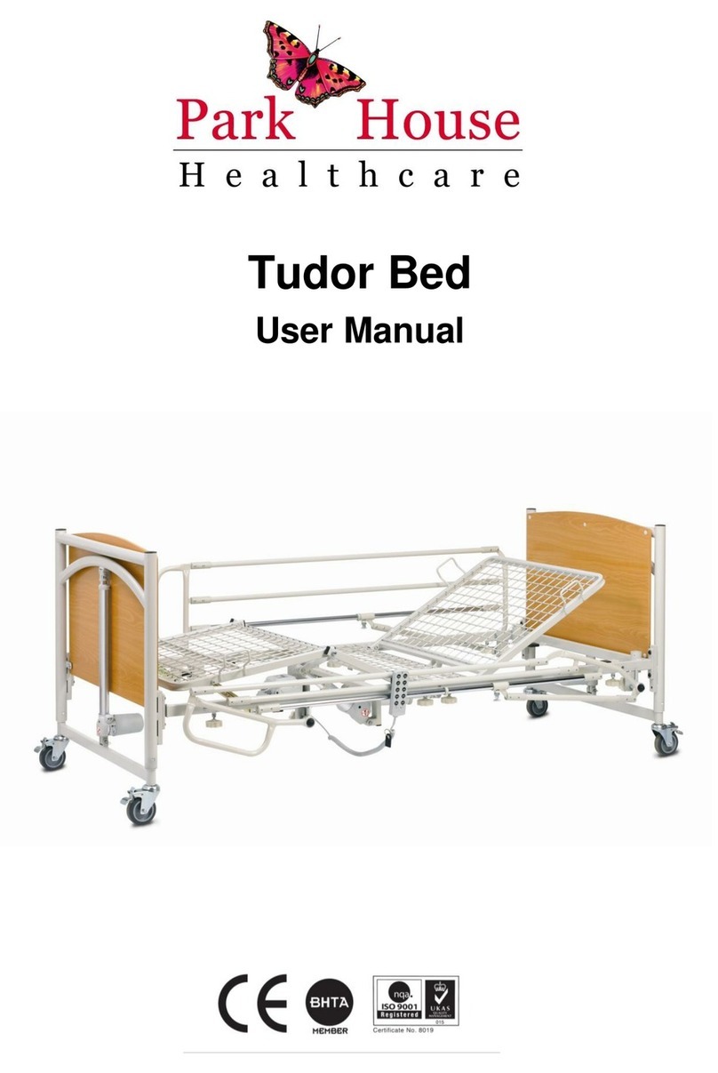
Park House Healthcare AMBIENCE User manual

AMBIENCE
Low Air Loss Mattress Replacement System
Service Manual

2008.01 V1.0
1
1PRODUCT VIEW ILLUSTRATION:...................................................................................... 2
1.1 FRONT VIEW ................................................................................................................2
1.2 PANEL VIEW ................................................................................................................2
1.3 SIDE VIEW 1 ................................................................................................................3
1.4 SIDE VIEW 2 ................................................................................................................3
1.5 REAR VIEW ..................................................................................................................4
1.6 BOTTOM VIEW………………………………………………………………………………………………….4
2SERVICE INSTRUCTION: .................................................................................................. 5
2.1 ALL PART ILLUSTRATION .................................................................................................6
2.1.1 BASE CAS E ASSE MBLY ………………………………………………………………………6
2.1.2 CONTROL PCB……………………………………………………………………………………………7
2.1.3 POWER PCB………………………………………………………………………………………………7
2.1.4 EMI PCB……………………………………………………………………………………………………8
2.1.5 TOP CASE ASSEMBLY……………………………………………………………………………………9
2.2 PUMP ASSEMBLY EXPLODED DIAGRAM……………………………………………………………………10
2.2.1 PUMP ASSEMBLY EXPLODED DIAGRAM/BOM …………………………………………10
2.2.2 TOP CASE ASSEMBLY EXPLODED DIAGRAM/BOM……………………………………16
2.2.3 BASE CASE EXPLODED DIAGRAM/BOM…………………………………………………17
2.2.4 HANDLE EXPLODED DIAGRA M/BOM……………………………………………………18
2.2.5 HANDLE ASSEMBLY DIAGRAM……………………………………………………………18
2.2.6 HANGER EXPLODED DIAGRAM/BOM……………………………………………………19
2.2.7 QUICK CONNECTOR EXPLODED DIAGRAM/BOM………………………………………19
2.2.8 BLOWER EXPLODED DIAGRAM/BOM……………………………………………………20
2.2.9 PRESSURE CALIBRATION PROCEDURE …………………………………………………21
2.2.10 CONTROL PANEL TESTING SOP…………………………………………………………24
3. SERVICE:
3.1 SERVICE REPAIR SOP…………………………………………………………………………………………26
3.1.1 NO POWER………………………………………………………………………………………………27
3.1.2 CONTROL PANEL HAS NO RESPONSE WITHIN POWER…………………………………………27
3.1.3 BLOWER IS UNABLE TO WORK………………………………………………………………………28
3.1.4 PUMP FAILURE WITHIN CPR ALARM IS ON………………………………………………………28
3.1.5 POWER FAILURE ALARM FAILURE…………………………………………………………………28
3.1.6 MAXFIRM FAULURE……………………………………………………………………………………29
3.1.7 FOWLER BOOST MALFUNCTION……………………………………………………………………29
4. TOOLS
4.1 LIST OF RECOMMENDED TOOLS AND EQUIPMENTS……………………………………………………………30

2008.01 V1.0
2
Panel View
(For AMBIENCE)
●On/Off Button
●Panel Lock Button
●Fowler Boost Indicator
●Max Firm Button
1 Product View illustration:
1.1 Front View
1.2 Panel View
●Low Pressure Key
●High Pressure Key
●Pressure Level Indicator
●Alarm Mute
●Low Pressure Alarm
●Power Failure Alarm
●CPR Alarm
Front View
(For AMBIENCE)

2008.01 V1.0
3
Side View 1
●Flower Boost Sensor Pad
Connector
●Air outlet
(Quick Connector)
Side View 2
Power switch
Power cord socket
1.3 Side view 1
+
1.4 Side view 2

2008.01 V1.0
4
Rear View
Handle
Pump
Bumper*4
Mounting
Bracket
Fuse Box*2
Bottom View
Pump
Cushion*4
Air Filter
1.5 Rear view
1.6 Bottom view

2008.01 V1.0
5
2Service Instruction:
Instruction for all general service repairs
Warning
Unplug power cord from mains,
ensure no electrical current is
detected prior repair.
Attention:
Before commencing the repair please follow instructions indicated
from below.
For all the required replacement parts, please contact
your agent for part number. Once the BOM
(Bill of Material) is obtained, proceed to the parts order
and repair as follows.

2008.01 V1.0
6
2.1 All part illustration
2.1.1 AMBIENCE Base Case Assembly
A. 120V/60Hz
B. 230V/50Hz
●Hanger
Assembly
●Power PCB
●Transformer
●EMI PCB
●Power Switch
●Main PCB
●Blower
●Connection
Tube
●Quick
Connector
●Rechargeabl
e Battery
●Main PCB
●Blower
●Connection
Tube
●Quick
Connector
●Rechargea
ble Battery
●Hanger
Assembly
●Power PCB
●Transformer
●EMI PCB
●Power Switch
Fig_2-1a
Fig_2-1b

2008.01 V1.0
7
●Ground Wire
Connecting Site
●Transformer AC
Input (110, 230V)
Connector
●Transformer AC Low
Voltage (10V)
connector
●AC Power Output
Connector
●Blower Control
Connector
●Transformer
High AC Output
●Control Panel
Connector
2.1.2 Control PCB
2.1.3 Power PCB
Fig_1-1
●Pressure Sensor
●Pressure
Calibrating
Circuit
Connecting Site
●CPR Function
Detecting
Connector
●Power PCB
Connecting Site
●Fowler Boost
Connector
●Control
Panel
Connector
●Rechargeabl
e Battery
Connector
●
Fig_2-4
Fig_2-3
Fig_2-2

2008.01 V1.0
8
2.1.4 EMI PCB
A. 120V/60Hz
B. 230V/50Hz
●Ground Wire
Point
●AC High
Voltage
Input Point
●AC High
Voltage
Output Point
Fig_2-5a
●Ground Wire
Point
●AC High
Voltage
Input Point
●AC High
Voltage
Output Point
Fig_2-5b

2008.01 V1.0
9
2.1.5 Top Case Assembly
●Control
Panel
Connector
Fig_2-6

2008.01 V1.0
10
2.2 Pump Assembly Exploded Diagram
2.2.1 AMBIENCE Pump Assembly Exploded Diagram/BOM.
A.120V/60Hz

2008.01 V1.0
11
AMBIENCE Pump Assembly BOM –120V/60Hz
NO
Item
PART NAME/SPECIFICATION
Quantity
1
F600A01-0000
Top case assembly
1
2
F602A01-0000
Base case assembly
1
3
604209-0000
Lead wire
1
4
604201-0000
Lead wire, brown
1
5
604202-0000
Lead wire, blue
1
6
604203-0000
Lead wire, white
2
7
664905-0000
Power cord socket
1
8
884203-0000
Lead wire, brown
1
9
884204-0000
Lead wire, blue
1
10
604204-0000
Ground wire
1
11
884501-0000
Fuse holder
2
12
664501-0000
Fuse
2
13
604901-0000
EMI PCB
1
14
885016-0000
Screws, M3*14mm
16
15
604001-0000
Transformer, 120V/60Hz
1
16
F607A03-0000
Power PCB
1
17
604205-0000
Lead wire
1
18
604206-0000
Lead wire
1
19
885304-0000
Washer
6
20
F607A04-0000
Control PCB
1
21
F609A02-0000
Hanger assembly
1
22
605101-0000
Hanger fixture
1
23
885014-0000
Screws
4
24
605102-0000
Hanger latching plate
1
25
605502-0000
Spring
1
26
601703-0000
Cushion, PU
1
27
605103-0000
Bolt
1
28
885004-0000
Washer
5
29
605501-0000
Spring
2
30
375003-0000
Screws, M3*10mm
1
31
665011-0000
Nut, M3
1
32
554401-0000
Blower, AC120V/50~60HZ
1
33
604207-0000
Lead wire
1
34
604208-0000
Lead wire
1
35
605001-0000
Screws, 5/32*6.0mm
1
36
605002-0000
Screws, 3/8"*10mm
1
37
F609A01-0000
Stuff
1
38
665009-0000
Screws, M4*15 mm
3
39
603405-0000
Connection Tube
1
40
604701-0000
Rechargeable Battery
1
41
883102-0000
Foam
1
42
601704-0000
Quick Connector (Male Base)
1
43
604302-0000
Reed switch assembly
1

2008.01 V1.0
12
44
885013-0000
Screws, M3*8 ㎜
2
45
F375A03-0000
Silicone tube
1
46
991812-0000
Zipper tip
2
47
F609A03-0000
Handle assembly
1
48
605005-0000
Screws, M4.0*32mm
4
49
662401-0000
Fuse sticker
2
50
602401-0000
Specification Sticker
1
51
602102-0000
Hanger instruction sticker
1
52
604101-0000
Power cord assembly
1
53
604301-0000
Power switch
1

2008.01 V1.0
13
B. 230V/50Hz

2008.01 V1.0
14
AMBIENCE Pump Assembly BOM –230V/50Hz
NO
ITEM
Part Name/Specification
Quantity
1
F600A01-0000
Top case assembly
1
2
F602A01-0000
Base case assembly
1
3
604209-0000
Lead wire
1
4
604201-0000
Lead wire, brown
1
5
604202-0000
Lead wire, blue
1
6
604203-0000
Lead wire, white
2
7
664905-0000
Power cord socket
1
8
884203-0000
Lead wire, brown
1
9
884204-0000
Lead wire, blue
1
10
604204-0000
Ground wire
1
11
884501-0000
Fuse holder
2
12
404501-0000
Fuse
2
13
604905-0000
EMI PCB
1
14
885016-0000
Screws, M3*14mm
16
15
F607A03-0000
Power PCB
1
16
604205-0000
Lead wire
1
17
604206-0000
Ground wire
1
18
885304-0000
Washer
6
19
F607A04-0000
Control PCB
1
20
F609A02-0000
Hanger assembly
1
21
605101-0000
Hanger fixture
1
22
605102-0000
Hanger latching plate
1
23
605502-0000
Spring
1
24
601703-0000
Cushion, PU
1
25
605103-0000
Bolt
1
26
885014-0000
Screws
4
27
885004-0000
Washer
5
28
375003-0000
Screws, M3*10mm
1
29
665011-0000
Nut, M3
1
30
F607A01-0000
Blower Assembly
1
31
605002-0000
Screws, 3/8"*10mm
1
32
F609A01-0000
Stuff
1
33
665009-0000
Screws, M4*15 mm
3
34
603405-0000
Connection Tube
1
35
604701-0000
Rechargeable Battery
1
36
883102-0000
Foam
1
37
601704-0000
Quick Connector (Male Base)
1
38
604302-0000
Reed switch assembly
1
39
885013-0000
Screws,M3*8mm
2

2008.01 V1.0
15
40
F375A03-0000
Silicone tube
1
41
991812-0000
Zipper tip
2
42
F609A03-0000
Handle assembly
1
43
605005-0000
Screws, M4.0*32mm
4
44
402401-0000
Fuse sticker
2
45
602402-0000
Specification Sticker
1
46
602102-0000
Hanger instruction sticker
1
47
604102-0000
Power cord assembly
1
48
604301-0000
Power switch
1
49
604002-0000
Transformer, 230V/50Hz
1
50
605501-0000
Spring
2
51
604210-0000
Lead wire
1

2008.01 V1.0
16
2.2.2 Top Case Assembly Exploded Diagram/BOM
Top case BOM
NO
Item
Part Name/Specification
Quantity
1
601001-0000
Top case, ABS., 94V-0
1
2
603101-0000
Foam, 94HF-1
1
3
604902-0000
Flexible PCB
1
4
603401-0000
Cushion, elastomeric
2
5
602101-0000
Quick Connector instruction label
1

2008.01 V1.0
17
2.2.3 Base Case Exploded Diagram/BOM
Base Case BOM
NO
Item
Part Name/Specification
Quantity
1
601201-0000
Base case, ABS., 94V-0
1
2
603102-0000
Foam, 94HF-1
1
3
601701-0000
Air filter cap, ABS., 94V-0
2
4
603103-0000
Air filter
2
5
601702-0000
Air filter cap, ABS., 94V-0
1
6
603406-0000
Cushion, elastomeric
4
7
603404-0000
Cushion, elastomeric
3
8
603401-0000
Cushion, elastomeric
2
9
885010-0000
Screws, M3*20mm
4

2008.01 V1.0
18
2.2.4 Handle Exploded Diagram/BOM
Handle BOM
NO
Item
Part Name/Specification
Quantity
1
605104-0000
Handle
1
2
601705-0000
Handle Fixing Pedestal (Left)
1
3
605004-0000
Screws, M5*19mm
2
4
601707-0000
Handle Fixing Pedestal –Plate (Left)
1
5
605003-0000
Washer
2
6
601709-0000
Handle Fixing Pedestal - Lock Pin
2
7
601706-0000
Handle Fixing Pedestal (Right)
1
8
601708-0000
Handle Fixing Pedestal –Plate (Right)
1
2.2.5 Handle Assembly Diagram
Item
Part Name/Specification
Quantity
F609A03-0000
Handle Assembly
1
1. Use a handle assembly for broken handle replacement.
2. Step A:Assemble one side of the handle assembly into the top case (referring upper
figure ).
3. Step B:Align the Handle Fixing Pedestal Lock Pin cross the handle assembly and washer
into the top case fixing hole (referring upper figure ).
4. Use holder to push the Handle Fixing Pedestal Lock Pin in until it stops.

2008.01 V1.0
19
2.2.6 Hanger Exploded Diagram/BOM
Hanger BOM
NO
Item
Part Name/Specification
Quantity
1
605301-0000
Hanger
1
2
603402-0000
Cushion, NBR
2
3
603403-0000
Cushion, NBR
1
2.2.7 Quick Connector Exploded Diagram/BOM
Quick Connector BOM
NO
Item
Part Name/Specification
Quantity
1
9918C7-0000
Quick Connector (Female Base)
1
2
Y9918C8-J001
Quick Connector Functional Cap
1
3
9918C8-0000
Quick Connector Functional Cap
1
4
9918C9-0000
Quick Connector Vacuum Valve
1
5
9918D1-0000
Quick Connector Adapter
2
8
9918D2-0000
Quick Connector Assemble Axle
1
4
999201-0000
Non-woven fabrics
1
7
995104-0000
Magnet Sensor, silver color, ψ5.0*t=4.0mm
1
8
995007-0000
Screws, M4*L25
1
Table of contents
Other Park House Healthcare Medical Equipment manuals

Park House Healthcare
Park House Healthcare BUTTERFLY COT User manual

Park House Healthcare
Park House Healthcare RICHMOND ULTRA LOW BED User manual

Park House Healthcare
Park House Healthcare Delta Plus User manual

Park House Healthcare
Park House Healthcare Tudor User manual

Park House Healthcare
Park House Healthcare PHASE III User manual

Park House Healthcare
Park House Healthcare RICHMOND User manual

Park House Healthcare
Park House Healthcare PHASE II User manual

Park House Healthcare
Park House Healthcare Endeavour User manual

Park House Healthcare
Park House Healthcare WARWICK User manual