manuals.online logo
Brands
  1. Home
  2. •
  3. Brands
  4. •
  5. Parker Pneumatic
  6. •
  7. Accessories
  8. •
  9. Parker Pneumatic MPS-3SS Series Installation and maintenance instructions

Parker Pneumatic MPS-3SS Series Installation and maintenance instructions

Pneumatic Division
Richland, Michigan 49083
!
!
WARNING
To avoid unpredictable system behavior that can cause personal injury
and property damage:
• Disconnect electrical supply (when necessary) before installation,
servicing, or conversion.
• Disconnect air supply and depressurize all air lines connected to
this product before installation, servicing, or conversion.
• Operate within the manufacturer’s specified pressure, temperature,
and other conditions listed in these instructions.
• Medium must be moisture-free if ambient temperature is below
freezing.
• Service according to procedures listed in these instructions.
• Installation, service, and conversion of these products must be
performed by knowledgeable personnel who understand how
pneumatic products are to be applied.
• After installation, servicing, or conversion, air and electrical
supplies (when necessary) should be connected and the product
tested for proper function and leakage. If audible leakage is present,
or the product does not operate properly, do not put into use.
• Warnings and specifications on the product should not be covered
by paint, etc. If masking is not possible, contact your local
representative for replacement labels.
WARNING
FAILURE OR IMPROPER SELECTION OR IMPROPER USE OF
THE PRODUCTS AND/OR SYSTEMS DESCRIBED HEREIN OR
RELATED ITEMS CAN CAUSE DEATH, PERSONAL INJURY AND
PROPERTY DAMAGE.
This document and other information from Parker Hannifin Corporation,
its subsidiaries and authorized distributors provide product and/or
system options for further investigation by users having technical
expertise. It is important that you analyze all aspects of your application,
including consequences of any failure and review the information
concerning the product or systems in the current product catalog. Due
to the variety of operating conditions and applications for these products
or systems, the user, through its own analysis and testing, is solely
responsible for making the final selection of the products and systems
and assuring that all performance, safety and warning requirements
of the application are met.
The products described herein, including without limitation, product
features, specifications, designs, availability and pricing, are subject
to change by Parker Hannifin Corporation and its subsidiaries at any
time without notice.
EXTRA COPIES OF THESE INSTRUCTIONS ARE AVAILABLE FOR
INCLUSION IN EQUIPMENT / MAINTENANCE MANUALS THAT UTILIZE
THESE PRODUCTS. CONTACT YOUR LOCAL REPRESENTATIVE.
Installation & Service Instructions
CVM-104P
MPS-3SS Series Sensor
ISSUED: June, 2003
Supersedes: July, 2002
Doc.# CVM-104P, ECN030385, Rev. 2
Introduction
Follow these instructions when installing, operating, or servicing
the product.
!
Mounting Bracket Kit (Included Parts)
2 Mounting Brackets
2 Mounting Screws
IP65 Kit (Included Parts)
1 O-Ring
1 Venting Nipple M3
Barb
Coupling
O-Ring
Ambient Air
Inlet Port
Caution
The MPS-3SS Pressure Sensor is designed to monitor pressure
and is not a safety measure to prevent accidents.
The compatibility of the sensor is the responsibility of the designer
of the system and specifications.
Operating Environment
•Parker / Convum Sensors have not been investigated for
explosion-proof construction in hazardous environments.
•Do not use with flammable gases, liquids, or in hazardous
environments.
•Avoid installing the sensor in locations where excessive
voltage surges could damage or affect the performance of
the sensor.
Operations
•Dedicate a power supply of 10.8 to 30VDC to the sensor
and set the ripple to Vp-p10% or less. Avoid excessive
voltage. Avoid voltage surges.
•A small amount of internal voltage drop is possible. Ensure
the power supply minus any internal voltage drop exceeds
the operating load.
•Verify the operating media is compatible with the specified
sensor. Check the chemical make-up, operating
temperatures, and maximum pressure ranges of the system
before installing.
•Installation of air dryer system is recommended to remove
moisture.
ANSI
•Depending on the system fluid and design, it may be
necessary to protect the diaphragm against pressure spikes
by installing a flow restriction upstream from the sensor.
Installation
•Never insert an object into the pressure port other than an
appropriate fluid connector.
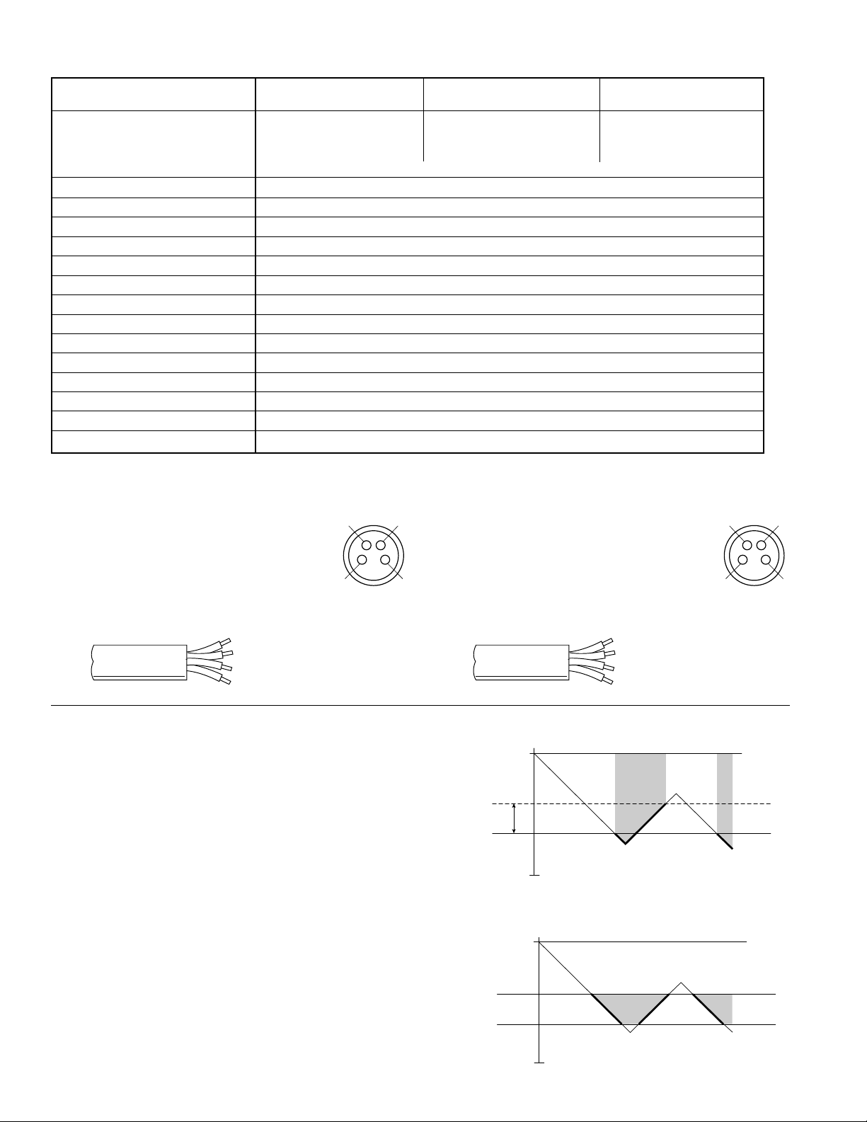
•Avoid short-circuiting the sensor. Connect the brown lead
to V+ and blue lead to 0V.
•Do not connect the output lead wires (black / white) to the
power supply.
•Outputs not being used should be trimmed and insulated.
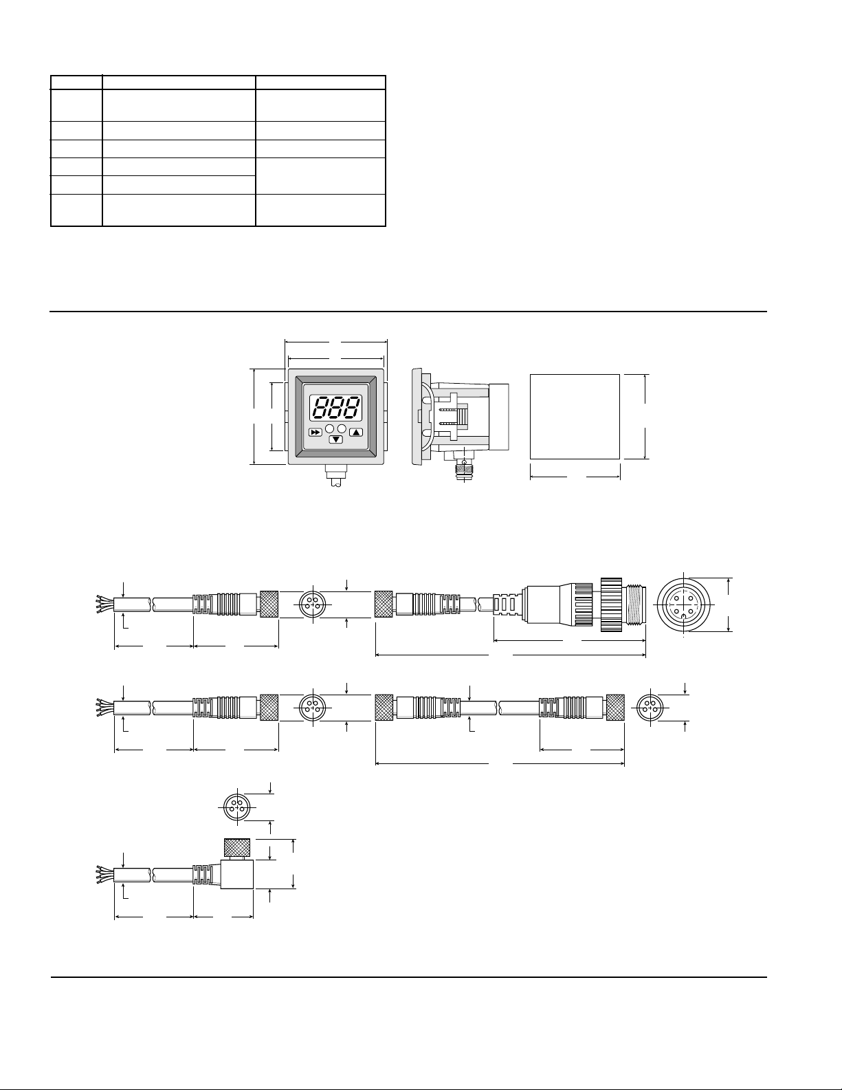
•Install using the metal mounting base.
•To achieve IP65 rating, connect the o-ring and barb to a
normal environment with a 2mm I. D. tube as shown below.
Output Modes
The MPS-3 Stainless Steel Series Sensor has two independent
NPN or PNP open collector output signals. An analog output is
optional.The Switch Output Mode has a switch point programmed
by the user at a specific pressure. The Hysteresis Range (h)
adjustment controls the output signal 0 to 100% below the Switch
Point (H).
The Window Comparator Mode provides two Switchpoint Settings
(A) and (b) that control the output signals (NPN / PNP) between
two pressures. This is referred to as the “High / Low” setting.
The optional Analog Output Signal is calibrated to the pressure
scale of the sensor.
MPS-3SS Series Sensor CVM-104P
2
h
H
off off
0
-30 in Hg
on on
A
b
off
off off
-30 in. Hg
0
on on
Switch Output
Window Comparator Output
2
1
4
3
Pin #
1 Brown: 24VDC
2 White: NPN / PNP Open Collector Output
3 Blue: 0VDC
4 Black: NPN / PNP Open Collector Output
Pin #
1 Brown: 24VDC
2 White: Analog 1 to 5VDC Output
3 Blue: 0VDC
4 Black: NPN / PNP Open Collector Output
2
1
4
3
Operating Pressure Range
Vacuum (V3F) Positive (P3S) Compound (R3F)
(0 to 30 inHg) (0 to 145 PSI) (-14.7 to 72.5 PSI)
bar: 0.001 bar: 0.01 bar: 0.01
Units of Measure kPa: 0.1 MPa: 0.001 kPa: 1
Display Resolution mmHg: 1 kgf/cm2: 0.01 kgf/cm2: 0.01
inHg: 0.1 PSI: 1 PSI: 0.1
Media Fluids, Non-Corrosive to 316L or 630 SUS
Pressure Port N: 1/8" NPSF, R: 1/8" BSPT, G: 1/8" BSPP, VC: Semi-Conductor Type Connector
Proof Pressure V3F: 145 PSI, P35: 290 PSI, R3F: 217.5 PSI
Operating Temperature 32 to 122°F (0 to 50°C)
Storage Temperature 14 to 140°F (-10 to 60°C)
Humidity 35 to 85% RH
Electrical Connection C: 4-Pin, M8 Connector, G: Grommet Open Lead
Power Supply 10.8 to 30VDC, Ripple Vp-p 10% Max., Reverse Voltage Protection
Display 3-Digit, 7-Segment LED
Display Refresh .1 to 3.0 sec. (Factory set at 0.1)
Output Circuit NPN (Sinking), PNP (Sourcing) Open Collector Transistor; 30VDC, 125mA
Switch Outputs 2 Output Signals, NPN or PNP, Normally Open or Closed, LED Indicator
Linear Output Optional Analog Output 1 to 5VDC
Output Modes Hysteresis or Window Comparator
Specifications
Brown V+
White NPN / PNP Output
Blue 0V
Black NPN / PNP Output
Lead Wiring
Brown V+
White Analog 1 to 5 VDC
Blue 0V
Black NPN / PNP Output
Lead Wiring
Sensor Pin Out Sensor Pin-Out with Analog Output
MPS-3SS Series Sensor CVM-104P
3
Programming
1 2 3
4 5 6
7 8 9
10 11 12
Output Set Open
or Closed Selecting
Units of Measure
Easy Mode
Activation
Output Mode 1
Hysteresis or
Window
Comparator
Output Mode 2
Hysteresis or
Window
Comparator
Output 1
Switch Point
Setting
Output 2
Switch Point
Setting
Automatic Teach Mode
& Auto Surveillance
Display Refresh
Settings / Output
Response Time
Interval
Lock Unlock
Special Display
Features
Zero
Reset
Display Peak Value
Bottom Value or
Their Difference
Vacuum
Cycle
Release
Cycle
Press 6x
Press for 3 Seconds
Press 1x
Hold
Press 1x
Press 7x Press 8x
Press 3x
Press 2x
Press 5x
Press 4x
Hold
Press 1x
Hold
Press 1x
Window Comparator Mode Window Comparator Mode
Hysteresis
Mode
Hysteresis
Mode
Low Low
High High
Peak
Value
Bottom
Value
Press 1x Press 1x
MPS-3SS Series Sensor CVM-104P
4
MPS-ACCH1
Panel Mounting
Bracket
1.57
(40)
1.72
(43,8)
1.57
(40)
1.31
(33,4)
1.42
(36)
(+0.5, -0.2)
1.42
(36)
(+0.5, -0.2)
Knockout
2
1
Error Messages
Display Description Solutions
Err
Zero Reset Error Reset Zero Below
3% of F.S.
Er1
System Error (Internal) Contact Factory
Er2
Auto Teach Mode Error Restart Function
CE1
Over current of Output 1 Load current exceeds
CE2
Over current of Output 2 maximum 125mA.
FFF
Applied pressure exceeds Apply pressures with
–FF
pressure range the rating of the sensor
Accessories
Cables
.196 (5) Dia
6.56 ft
(2m)
6.56 ft
(2m)
1.26
(32)
CB-M8-4P-2M
CB-M8-4P-5M CB-M8-4P-M8-2M
CB-M8-4P-M12-2M
CB-M8-4P-5M-90
.196 (5) Dia
.38
(9,7) Dia
16.40 ft
(5m)
1.26
(32)
.38
(9,7) Dia
.47
(12) Di
a
.38
(9,7) Dia
.196 (5) Dia
6.56 ft
(2m)
1.26
(32)
2.09
(53)
.196 (5) Dia
.38
(9,7) Dia
16.40 ft
(5m)
.87
(22)
.42
(10,7)
.75
(19)
Replacement Kits
MPS-ACCK1 ............................................ Mounting Bracket Kit
MPS-4-IP65 .................................................................. IP65 Kit

This manual suits for next models

1

Other Parker Pneumatic Accessories manuals

Parker Pneumatic MPS-1 Series Installation and maintenance instructions

Parker Pneumatic

Parker Pneumatic MPS-1 Series Installation and maintenance instructions

Parker Pneumatic MPS-2 Series Installation and maintenance instructions

Parker Pneumatic

Parker Pneumatic MPS-2 Series Installation and maintenance instructions

Parker Pneumatic MPS-31 Series Installation and maintenance instructions

Parker Pneumatic

Parker Pneumatic MPS-31 Series Installation and maintenance instructions

Popular Accessories manuals by other brands

Sure Electronics CPL-312C24 quick guide

Sure Electronics

Sure Electronics CPL-312C24 quick guide

Smarthome Group iVDP2 user manual

Smarthome Group

Smarthome Group iVDP2 user manual

Carlon Wireless Chime Button Instruction guide

Carlon

Carlon Wireless Chime Button Instruction guide

Honeywell Home 3 Series manual

Honeywell Home

Honeywell Home 3 Series manual

Braebon Ultima 0580A user guide

Braebon

Braebon Ultima 0580A user guide

Nitecore NB10000 user manual

Nitecore

Nitecore NB10000 user manual

Vega FIBERTRAC 31 operating instructions

Vega

Vega FIBERTRAC 31 operating instructions

HYPO SOURCE HYPO 7.5 datasheet

HYPO SOURCE

HYPO SOURCE HYPO 7.5 datasheet

Ravpower RP-PB194 user manual

Ravpower

Ravpower RP-PB194 user manual

Campbell SDMS40 product manual

Campbell

Campbell SDMS40 product manual

JETI model MULi6s EX Instructions for using

JETI model

JETI model MULi6s EX Instructions for using

MAGINON MPP 5200-LI user manual

MAGINON

MAGINON MPP 5200-LI user manual

System Sensor 7251 Installation and maintenance instructions

System Sensor

System Sensor 7251 Installation and maintenance instructions

Nevadent NZR 1.5 A1 operating instructions

Nevadent

Nevadent NZR 1.5 A1 operating instructions

EdenPURE 360 Super Climater Easy Start Up Guide

EdenPURE

EdenPURE 360 Super Climater Easy Start Up Guide

HORNER HE693THM166 installation manual

HORNER

HORNER HE693THM166 installation manual

Soehnle LQ240050U user manual

Soehnle

Soehnle LQ240050U user manual

Huawei NetCol8000-A013 user manual

Huawei

Huawei NetCol8000-A013 user manual

manuals.online logo
manuals.online logoBrands
  • About & Mission
  • Contact us
  • Privacy Policy
  • Terms and Conditions

Copyright 2025 Manuals.Online. All Rights Reserved.