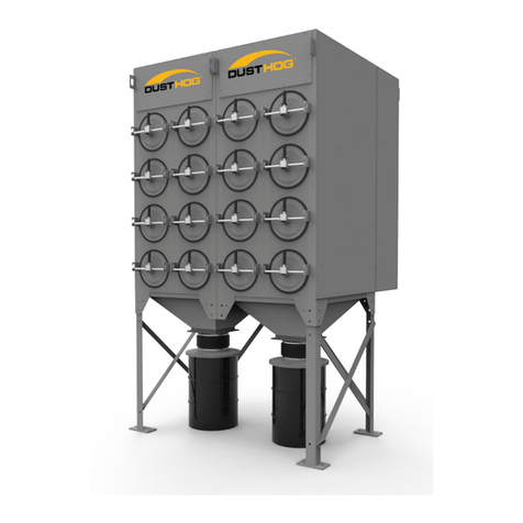
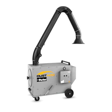
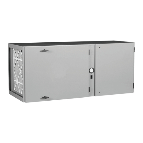
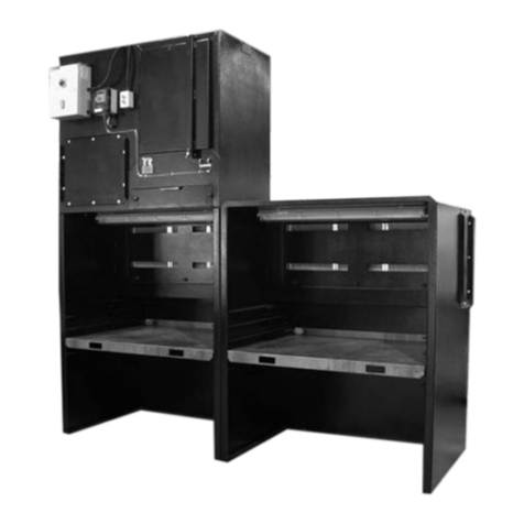
Parker DUSTHOG PNP User manual

DUSTHOG Plug & Play Fume & Dust
Collector Owner’s Manual
Model PNP

DUSTHOG PNP Series
i
KNOW YOUR EQUIPMENT
READ THIS MANUAL FIRST.
Your DUSTHOG®PNP system should provide many years of trouble-free service. This manual
will help you understand the operation of your PNP unit. It will also help you understand
how to maintain it in order to achieve top performance. For quick future reference, fill in the
system and filter information in the spaces below. Should you need assistance, call the Parker
customer service number shown below. To expedite your service, have the following information
available when contacting Parker.
Unit Order #: __________________________________________________________________
Unit Model #: __________________________________________________________________
Unit Serial #:___________________________________________________________________
System Accessories:
______________________________________________________________________________
______________________________________________________________________________
______________________________________________________________________________
Installation Date: _______________________________________________________________
Parker Hannifin Customer Service
1-800-343-4048

DUSTHOG PNP Series
ii
Table of Contents
1.0 Important Notice ..................................................................................................................... 1
2.0 Introduction ............................................................................................................................. 1
2.1 DUSTHOG Nomenclature ................................................................................................... 1
2.2 Equipment Description........................................................................................................ 2
2.3 Principal of Operation ......................................................................................................... 2
3.0 Installation ............................................................................................................................... 4
3.1 Inspection and Off Loading................................................................................................. 4
3.2 Installation Preparation and Planning................................................................................... 6
3.3 Mechanical Installation ........................................................................................................ 6
Compressed Air Connection.................................................................................................. 6
Fire Suppression System ....................................................................................................... 6
Inlet Ducting Connection........................................................................................................ 6
Drawer Liner Installation......................................................................................................... 8
After-Filter Installation/Replacement ....................................................................................... 8
3.4 Electrical Connection .......................................................................................................... 8
Electrical Supply Power ....................................................................................................... 10
Electrical Touchscreen Controls ........................................................................................... 10
Remote Controls Panel........................................................................................................ 10
Process Control ................................................................................................................... 11
Step-Down Transformer Package ........................................................................................ 11
4.0 Unit Operation....................................................................................................................... 11
4.1 Start-up ............................................................................................................................ 11
4.2 System Operation ............................................................................................................. 12
Airflow Adjustment Using Manual Speed Control................................................................. 12
Airflow Adjustment Using Auto-Flow Control........................................................................ 12
Filter Pulse Cleaning System Operation ............................................................................... 12
4.3 Touchscreen Operation ..................................................................................................... 13
Start-up and Home Screen.................................................................................................. 13
Standard Format.................................................................................................................. 13
Basic Screens...................................................................................................................... 13
Auto-Flow Screen ................................................................................................................ 15
After-Filter ............................................................................................................................ 15
Customer Settings............................................................................................................... 16
5.0 Service................................................................................................................................... 18
5.1 General Maintenance Guidelines....................................................................................... 18
5.2 Primary Filter Installation / Replacement............................................................................ 18
5.3 Cleanout of Spark Arrestor................................................................................................ 18
5.4 Emptying Dust Drawer ...................................................................................................... 19
6.0 Troubleshooting Guide ......................................................................................................... 20
7.0 Replacement Parts ............................................................................................................... 22
8.0 Appendix - Wiring Diagrams ................................................................................................ 24

IMPORTANT SAFETY INSTRUCTIONS
To reduce the risk of fire, electric shock, or injury when using your air cleaner, follow these basic precautions:
! WARNING
SAFETY PRECAUTIONS
We have provided many important safety messages in this manual and on the DUSTHOG PNP Fume & Dust
Collector. Always read and obey all safety messages.
• Wear protective clothing and safety glasses when
handling collector components or servicing the unit.
• Use proper lifting and rigging equipment to install
your dust collector (or unit)
• Disconnect power before servicing.
• Replace all access panels before operating.
• Do not operate the unit with component doors open.
• Electrical connections should only be made by
qualified personnel and be in accordance with local
and national codes and regulations.
• Do not use in explosive atmospheres.
• Do not collect emissions which are explosive.
• Keep flammable materials and vapors, such as
gasoline, away from unit.
• The unit should be inspected frequently and
contaminants removed to prevent excessive
accumulation which may result in flash-over
or fire damage.
• Operate only in a safe and serviceable condition.
• Operating temperature to the air stream should not
exceed 120° F (49° C).
!
!DANGER
!WARNING
!CAUTION
CAUTION
This is the safety alert symbol.
This symbol alerts you to potential hazards that can kill or hurt you and others. All safety messages
will follow the safety alert symbol and the word “DANGER”, “WARNING”, or “CAUTION”.
These words mean:
Indicates a hazardous situation which, if not avoided,
will result in death or serious injury.
Indicates a potentially hazardous situation which, if not avoided,
could result in death or serious injury.
Indicates a potentially hazardous situation which, if not avoided,
may result in minor or moderate injury.
CAUTION used without the safety alert symbol indicates a potentially
hazardous situation which, if not avoided, may result in property damage.
iii
!

1
COMBUSTIBLE DUST HAZARDS –
SMOG-HOG®and DUST-HOG®Pollution Control Systems
Pursuant to National Fire Protection Agency (NFPA) Standards, the owner/user is required to test their dust mixtures
to evaluate and understand potential combustion or deflagration hazards that may exist. In addition, NFPA standards
require the owner/user to perform and have record of a Dust Hazard Analysis (DHA) if there is potentially a combustible
material involved within or exposed to the process.
The DHA serves as a systematic review of the process to:
1) Identify where fires and explosions can occur;
2) Identify the potential causes and consequences, and;
3) Determine if existing and proposed safeguards are sufficient.
It is the responsibility of the owner/user to evaluate, interpret and document any associated risk in their process
including adherence and compliance to any and all applicable local, state and federal codes, standards, laws and
regulations.
It is the sole responsibility of the equipment owner/user of record to coordinate and perform sample material collection
and combustion/explosivity testing of any and all dust and material that will be extracted and filtered by the Air Pollution
Control (APC) filtration equipment and to notify Parker of the results prior to any discussion involving equipment
specification and solution recommendation. It is recommended to utilize a Certified Industrial Hygienist (CIH) or certified
safety expert that is properly trained, licensed and approved and to use a licensed and approved dust testing facility
for proper dust and material analysis, testing protocol and reporting procedures. A sample of testing facilities and list of
Industrial Hygiene (CIH) and other occupational and environmental health and safety (OEHS) consultants can be located
through AIHA (American Industrial Hygiene Association) website.
To minimize the risk of fire or explosion, user must ensure proper installation, operation and maintenance of Parker
equipment. Since application, installation, operation and maintenance are beyond the control of Parker, Parker disclaims
any liability or responsibility for damage from fires or explosions regardless of origin. Parker recommends that all APC
dust collection equipment, installation and application conform to any and all applicable local, state and federal
standards, codes, laws and regulations including the addition of appropriate fire or explosion protection systems
including but not limited to venting, mitigation, suppression and isolation when and where required. Installation of
Parker equipment should be by a licensed contractor that is also experienced in potential fire and explosion hazards
and adheres to related local, state and federal codes, standards, laws and regulations. Parker is not an expert nor
certified design consultant in relation to spark, fire or explosion mitigation including but not limited to detection,
mitigation, suppression and isolation pf combustible dusts and materials. Therefore, Parker recommends that any
industrial air filtration system recommendation, design or solution be reviewed, approved, stamped and signed by
an industry expert consultant in air filtration systems, combustible dust/materials or certified safety expert such as a
Certified Industrial Hygienist (CIH) or a Certified Professional Engineer (PE) who is a licensed and certified expert with
industrial filtration system design and application including adherence and compliance to any and all applicable local,
state and federal codes, standards, laws and regulations.
Pursuant to Parker’s Offer of Sale (terms and conditions) and by accepting the purchased equipment, Buyer and owner/
user agree to defend, indemnify, and hold harmless Parker, its successors, assignees, suppliers, shareholders, directors,
officers, employees, agents, and affiliated companies from all losses, costs, damages, demands, claims, liabilities, fines,
penalties or any other expenses (including attorneys’ fees, court costs, and expert fees) (collectively “losses”), caused or
contributed to in any way by Buyer or owner/user’s failure to follow these instructions and/or failure to properly install,
apply, operate, or maintain the equipment purchased from or supplied by Parker, or losses caused or contributed to in
any way by Buyer’s and owner/user’s failure to provide accurate information, specifications or dust explosivity values.

Page intentionally left blank

3
1. Important Notice
This manual contains important safety information and precautionary measures. It is impossible to list
all potential hazards associated with every collection system in each application. Proper use of the
equipment should be discussed with Parker Hannifin, Inc. or your local Parker representative.
Operating personnel should be aware of, and adhere to, the most stringent safety procedures
• Do not collect explosive dusts or fume.
• Avoid mixing combustible materials such as aluminum, paper, wood or other organic dusts with dusts
generated from grinding metals. A fire hazard could develop from sparks entering the dust collector.
• When collecting emissions from spark-producing processes, care must be taken to reduce any
potential fire hazards.
System design should include methods to prevent sparks from entering the dust collector.
Dust collectors do not contain fire-extinguishing equipment.
• Your dust collector was selected for a particular application. Consult Parker prior to making any
application or system changes.
2. Introduction
Thank you for selecting DUSTHOG fume/dust collection equipment to assist you in your commitment
to a clean and safe environment. We trust that in purchasing our product, you have recognized our
commitment to continually offer air cleaning equipment engineered to each collection need and
manufactured to the highest standards. If at any time you have a question about dust collection,
please do not hesitate to call your local Parker representative.
2.1 DUSTHOG Nomenclature
DUSTHOG air filtration systems are available in a variety of configurations and sizes. Codes shown
below identify characteristics which might be built into a given unit. Blower quantity will be the other
significant factor in unit configuration.
PNP-XX
Quantity of filters deep
Quantity of filters wide
Models: PNP-12, PNP-22, PNP-32
The PNP is a free standing, self contained, fume/dust filtering unit with a dust cabinet and a removable,
easy-empty dust collection bin, primary filter cabinet, compressed air pulse cleaning system, blower
cabinet, and controls. Optional after filters are available for final stage filtration.
The purpose of this manual is to provide the proper installation, operation, and general maintenance
guidelines for the PNP. As you review this manual, refer to Figure 1 for assistance in identifying components
of the dust collector.
The PNP dust collector has been designed to provide you with exceptional fume/dust collection
capabilities and reliable, long-term field operation. We suggest that you thoroughly review this manual
prior to installation and startup of your system.
If your PNP has optional equipment included as part of your order, specific operations and maintenance
manuals for these accessory systems may be included. If applicable, site specific installation and other
drawings will also be included.
If you require assistance in the installation, startup, operation, maintenance or troubleshooting of your air
cleaning equipment, contact your local Parker sales representative.
!DANGER

4
DUSTHOG PNP Series
2.2 Equipment Description
This section will briefly describe each component in the PNP and its role in the system’s operation.
Dust Drawer
Most units will include a dust drawer where all collected fume or dust will fall into during filter cleaning.
Angled flanges will direct dust that is blown off of the primary filters into a dust bin. Behind the lowest
door on each cabinet, one 20 gallon bin will be housed behind each door of the cabinet (drawer quantity
dependent on unit size). They can be accessed and maneuvered to a disposal site where an easy-empty
design allows for disposal or recycling of collected material.
Filter Cabinet
The filter cabinet consists of the primary cartridge filters which are accessed through a hinged door on
the front of the module. The filters are moved in and out of the cabinet and sealed to the tubesheet with
a cambar mechanism.
The PNP comes standard with ProTura DH nanofiber technology cartridge filters. Additional media options
and filter configurations are available and may have been specified for your application.
Pulse Cleaning System/Blower Cabinet
The compressed air pulse cleaning system is used to dislodge collected contaminates from the filters
with bursts of air directed through cleaning nozzles. One filter is cleaned at a given time by controlling
the solenoids on the manifold with the cleaning system programmed into the touch screen display.
The controls for the cleaning system and all other electronics are housed in this cabinet.
The compressed air supply connection is located on the rear of the cabinet.
The system control panel is located at the front of the module on a tool operated, hinged access panel.
The supply power for the system is located at the rear of the cabinet.
The blower(s) is also located within this module immediately above the pulse cleaning system. The blower
is an Electronically Commutated (EC) motorized impeller assembly. Depending on airflow requirements,
there may be several blowers in this compartment installed in parallel.
2.3 Principal of Operation
The purpose of the PNP is to collect fugitive dust generated by various industrial processes during operation.
The collected fume or dust is pulsed off of the primary filters directly back into the unit dust drawer. The dust
bin can be emptied directly into a drum or container of the customers choice for recycling or disposal.
Differential Pressure
Differential pressure, also referred to as pressure drop (ΔP), is an indication of the resistance to airflow
across the filter elements. Differential pressure is commonly measured in inches of water column (W.C.).
It is normal for the differential pressure to increase as the collector operates. Any sudden increase or
decrease in differential pressure may indicate a problem in the collector (blinded filters, leaks or other
cause) that requires immediate attention. See troubleshooting guide in section 6 for assistance.
The operating differential pressure displayed on the unit will typically run between 0.5 to 3.0 in. W.C.
(124.4 to 746.5 Pa) for a primary cartridge. The expected pressure range for the after-filters is
0.5 to 3.0 in. W.C. (124.4 to 746.5 Pa).

5
DUSTHOG PNP Series
Figure 1B
PNP Equipment Description
61-10120
Figure 1A
PNP Equipment Description

6
DUSTHOG PNP Series
3. Installation
3.1 Inspection and Off Loading
As soon as your equipment arrives, carefully inspect the items to ensure they are in good condition and
that all items listed on the packing list have been received. Even though the items are carefully loaded
and tied down at the time of shipment, it is possible for them to be damaged in transit.
Report any damage(s) and/or shortage(s) immediately. It becomes increasingly difficult for either the
carrier or the supplier to assume responsibility for any damages after too much time has transpired.
Check all loads separately.
The following steps should be taken immediately upon receipt of your shipment, which will assure and
expedite claim payments and replacement of missing or damaged items.
1. Begin your inspection of the shipment BEFORE it is unloaded.
2. Check for damage to any exposed items, particularly at the tie-down locations.
3. Photograph any damage. Do this BEFORE the equipment is unloaded.
4. Check Bill of Lading quantities and description. Note any discrepancies on all copies of the Bill of
Lading and have them acknowledged (the carrier should sign). Damage description should also be
written directly on, or attached to, the Bill of Lading, and should also be signed by the driver.
Contact the insurance company and the shipper at once so that damages and/or shortages can be
corrected and a claim can be filed without delay.
TIP OVER HAZARD
Lift the PNP unit and components by the packing skids or on the lifting eyes located on the top of the
unit in each corner.
3.2 Installation, Preparation, and Planning
Prior to the actual installation of the PNP, the location should be readied. This would include having an
adequate laydown area for all components, and access for the crane, forklifts and other machinery.
The unit will come mostly pre-assembled. The majority of installation will be ducting, mounting, or
securing the unit. An electrical source, lighting and other equipment should be readily available to aid in
the installation.
In most cases engineering drawings of your specific equipment and options will be provided. These
and all available documentation for your system should be thoroughly reviewed prior to beginning any
installation work. This includes the unit and electrical controls. Ensure to leave an appropriate amount
of room around your unit to allow for maintenance and servicing. A minimum of 2-1/2 feet (0.76 m)
of clearance is recommended for service in front of the filter access door and 3 feet (1 m) for the rear
electrical access per NEC.
Ensure there is adequate access to the electrical components with ducting installed.
Ensure to position the unit so that the clean air discharge is directed into an open area free of
obstructions and with consideration for personnel safety.
!DANGER

7
DUSTHOG PNP Series
61-10121
Figure 2
PNP Weights and Lifting Info

8
DUSTHOG PNP Series
3.3 Mechanical Installation
CRUSH HAZARD
Use adequate safety measures when lifting and assembling any heavy components.
Consult your plant safety personnel for recommendations.
Connect lifting slings and spreader bars to lifting lugs with clevis pins. Use spreader bars to distribute
the load evenly. Location must be clear of all obstructions, such as utility lines or roof overhangs.
All units are supplied with a dust drawer base that must be secured to the floor using the base plate
mounting holes. An inlet box will be factory installed. The inlet is a round collar mounted on the vertical
surface of the rear inlet box. Be sure to use a proper sealant or gasket when installing any inlet collars
to prevent leaks. Inlet collars are mounted with 1/4-20 hardware utilizing the existing nut inserts in the
top of the inlet box.
All other transitions, ducting or plenums required for unit set-up and operation are customer sourced.
Unit should ALWAYS be secured to the floor when installed in this configuration.
3.3.1 Compressed Air Connection
Shut off, lock out, and slowly release the pressure in the compressed air piping and/or the PNP
compressed air manifold, and verify that the pressure has been released by observing a pressure
gauge, known to be in good working order.
Liquid water and oil must not be allowed to enter the compressed air manifold on the PNP unit from
the factory compressed air line. To ensure a liquid-free compressed air supply, Parker recommends
installing a point of use coalescing filter with an automatic drain port prior to the unit.
Consult your local Parker representative for information regarding coalescing filters
The PNP unit has a 1” FNPT compressed air connection on the rear of the unit. Clean, dry compressed
air at an inlet pressure of 90-110 PSIG (6.2-7.2 barg) is required to operate the pulse cleaning system.
A shut-off/lock-out valve, a pressure gauge, and a pressure regulator, if needed, should be installed
downstream of the coalescing filter, and connected to the compressed air connection on the rear of the
PNP unit.
3.3.2 Fire Suppression System
Fire suppression connections are built into the dirty and clean air cabinets. They will come plugged
from the factory and are meant to serve as a means for the customer to add a fire suppression system
if they deem it necessary. See Figure 1B for basic locations and size of connections. Consult applicable
fire codes for proper selection, sizing and operation of a fire suppression system.
3.3.3 Inlet Ducting Connection System
The connection of the ducting into the unit, by means of the inlet box that will come installed on most
units, is recommended to be done by an experienced installer. All components connecting to the inlet
box are to be sourced by the customer.
Be sure to install the ducting in a manner that will still allow the removal of the electrical access panel
(shown in Figure 1B) so minimal access can be gained. For example, if a circuit breaker needs to be
switched or reset.
!DANGER
!CAUTION

9
DUSTHOG PNP Series
Figure 3
Drawer Liner Replacement
3.3.4 Drawer Liner Installation
Your unit may have been purchased with an optional drawer liner. If this is the case ensure that the bag
and hold-down bracket is installed correctly and is secured to the drawer. The bag should be set in the
drawer and spread out evenly. The hold-down bracket is set on top carefully, as to not rip the bag, and
lowered into place.

10
DUSTHOG PNP Series
VOLT PH
BLOWER QTY.
HZ RPM FLA XFMR
380 3 1 50-60 4,200 6.7 ---
480 3 1 50-60 4,200 5.5 ---
575 3 1 50-60 4,200 11.4 5kVA
380 3 2 50-60 4,200 12.9 ---
480 3 2 50-60 4,200 10.5 ---
575 3 2 50-60 4,200 21.8 10kVA
380 3 3 50-60 4,200 19.1 ---
480 3 3 50-60 4,200 15.5 ---
575 3 3 50-60 4,200 32.2 15kVA
380 3 4 50-60 4,200 25.3 ---
480 3 4 50-60 4,200 20.5 ---
575 3 4 50-60 4,200 42.5 30kVA
TABLE 1
PNP Voltage and Full Load Amps
Power cord and connection into unit will be supplied by the customer.
3.3.5 After-Filter Installation/Replacement
If an after-filter option is selected by the customer, those filters will be shipped separate of the unit to
be mounted following unit installation at the customer facility.
Proper removal and installation of each filter type is shown in Figure 4.
Center the filters atop the unit when viewed from the front, the two after-filters will be butted against
each other in the center of the unit (looking at it from the side) from front to back just as with the
internal filters. Reference balloon #4 in Figure 4.
The hold-down brackets are to be placed on top of the filters as shown and secured down with all-
thread rods, washers and nuts. Tighten nuts using hand tools and be sure not to over compress the
gasket on the bottom side of the after-filter. Minimal torque should be applied, just enough to cinch
down each bracket so it can’t slide around on top the filter(s). The gasket on the filter should be
compressed by 30-50%. A center bracket is also supplied that runs in the same direction, it is placed
immediately over the seam where the two filters are butted together. Reference balloon #5 in Figure 4.
Larger size unit after-filter setups will be installed in an identical fashion. The filters will always be
installed in-line, directly over the perforated square cutouts on the top panel.
If a housed after-filter option is selected, the install will be similar except there will be a cabinet to
insert the filters into. They will rest on cam bars the same style as the ones used in the primary filter
cabinet. When the filters are inserted and pushed all the way back into the cabinet the cams can be
rotated upward to seal the filters. Reference balloon #6 in Figure 4B.
3.4 Electrical Connection
The PNP customer electrical connections are located on the rear of the unit as shown in Figures 1B.
The supply voltage and FLA will be noted on the nameplate. The blower and pulse cleaning system
controls are factory pre-wired for operation. The touchscreen controls are also pre-wired for the integral
option, but require field wiring and connections for the remote display enclosure option.
Wiring diagrams for the various PNP controls, blower arrangement and supply voltage options are
available within the appendix of this manual. Note that the PNP does not contain the main disconnect
or fuses for the supply power. Electrical installation should be completed by a qualified professional and
done in accordance with all applicable codes and regulations.
Unit is available in the voltages shown below:

11
DUSTHOG PNP Series
61-10122
Figure 4B
After-Filter Removal and Installation
Figure 4A
PNP Primary Filter Removal & Installation

12
DUSTHOG PNP Series
3.4.1 Electrical Supply Power
The main power supply is connected to the PNP unit through a 1˝ FNPT coupling located on the rear
of the unit shown in Figure 1B. After feeding wires through the coupling, terminations are made on
the main bus bar terminal for each phase and frame ground connection. The rear electrical panel also
contains the unit circuit breakers and DC power supply for the controls components. Utilize Table 1
for wire, fuse and disconnect sizing for your respective product model. A second plugged 1˝ FNPT
coupling is also located on the rear of the cabinet for low optional voltage connections using the
process control feature to automate operation. Ensure that the rear electrical panel cover is in place
and secured prior to operating the unit. Refer to the electrical wiring diagrams in Table 2 for additional
wiring information.
Note: When making the main power connections to the unit, fan rotation check is not required.
The blower will automatically turn in the correct direction.
Descripon of Wire Diagram Appendix
Transformer 575:480 A1
One Blower & Controls A2
Two Blower & Controls A3
Three Blower & Controls A4
Four Blower & Controls A5
Remote Panel Controls A6
One Blower & Remote Controls A7
Two Blower & Remote Controls A8
Three Blower & Remote Controls A9
Four Blower & Remote Controls A10
TABLE 2
Wire Diagrams
3.4.2 Electrical Touchscreen Controls
The main control panel for the PNP unit is a touchscreen interface located integrally on the front of
the unit or remotely in an auxiliary enclosure (refer to section 3.4.3) that operates the blower and filter
pulse cleaning system. Both the touchscreen control panel and filter pulse cleaning valves are powered
by 24V DC. Refer to Section 4 of this manual for operation of the touchscreen. All wiring in the
touchscreen controls panel is pre-wired at the factory and there are no customer connections at this
panel. The panel door should remain closed and locked during operation.
3.4.3 Remote Controls Panel
The PNP unit is available with a remote controls panel that allows touchscreen controls to be located
within 100 ft. (30.5 m) from the PNP unit location. The controls are provided in a NEMA 4X enclosure
for mounting. The remote display panel will come pre-wired with two cables, one is the 24 VDC power
supply, along with control cables and the other is a communications cable that must be connected
to the PNP unit upon installation. Note that these wires are low voltage and should not be run next to
high voltage wires. These wires should be cut to final length at installation.

13
DUSTHOG PNP Series
3.4.4 Process Control
The customer has the option to control the PNP ON-OFF operation with a dust/fume generating
equipment or process. This will allow the operator to control the PNP with a “Dry-Contact” off another
piece of equipment. Refer to the wiring diagrams in the appendix for wiring of this option and to
Section 4 for process control set up on the touchscreen.
Wiring will be terminated to the terminal blocks located in the rear electrical panel in Figure 1B.
When the machine dry contact is closed, the PNP blower will be on and when the contact is open,
the PNP unit blower will shut down.
Note: A relay coil cannot be connected to the PNP and will not work for this type of electrical circuit.
3.4.5 Step-Down Transformer Package
An auxiliary 575V step down transformer is an available option for the PNP. This transformer ships
loose and requires field installation by a qualified individual. Refer to Appendix page A1 for additional
details including primary and secondary transformer full load amps (FLA) for sizing fuses, electrical wire
and main disconnect.
Note: The transformer cannot be attached to the PNP, the PNP structure will not support the weight of
this device.
4. Unit Operation
4.1 Start-Up
Before system start-up, verify that the installation is complete per Section 3 of this manual.
The following are the basic steps to walk you through as you are starting up.
1. Open the PNP filter access doors and verify that the filters are in place and properly sealed.
2. Open the dust drawer access door and verify that the dust drawer is in place.
3. Close and latch all access doors and electrical enclosures on the dust collector.
4. Ensure that the main power is connected and turned on.
5. Ensure that the compressed air is connected and turned on.
6. Follow Section 4.3 for setting changes on the touchscreen to target the desired airflow volume.
Adjust the blower speed to the RPM % that will provide the targeted airflow. For assistance in
determining the target RPM, contact your local representative. When using the Auto Flow option,
follow the Auto Flow Settings in Section 4.
7. Using the customer service menu in the touchscreen, you can test each pulse valve to verify
operation. Refer to Section 4 for this procedure. Adjust any of the optional pulse cleaning settings
such as cleaning mode or downtime cleaning settings as necessary in the customer service menu.
8. Press the blower power button on the Home screen to begin operation. Note that if the dust collector
is connected to a process, other equipment will need to be engaged as well.
9. Verify performance of the dust collection system by measuring airflow or evaluating capture at each
collection point. It is recommended to record baseline performance parameters so in case of an upset
condition or system changes, the system can be reset. The recorded data should include the static
pressure at each collection hood, system amperage draw, and filter pressure drop at a minimum and
any other key pieces of data critical to your process.

14
DUSTHOG PNP Series
4.2 System Operation
As the PNP collects contaminate, the filter will build up a dust cake on the outside surface causing
the filter pressure drop to rise. As the pressure rises, the filters will need to be cleaned or blower
RPM increased in order to maintain the desired airflow. When the filters are cleaned, the dislodged
contaminant will drop to the bottom of the dust collector and collect within the dust drawer where it can
be removed and disposed of. When the system can no longer generate the airflow required to capture or
convey the collected contaminate, the filters will need to be changed.
4.2.1 Airow Adjustment Using Manual Speed Control
The PNP features an Electronically Commutated (EC) blower that is equipped with airflow adjustment
using the blower RPM. To adjust the airflow, the RPM can be adjusted from 20% to 100% of the
blower rated RPM. As filter pressure builds, it may be necessary to increase the RPM to maintain
proper capture and transport velocity within the hood and duct system. The adjustment of the RPM is
done in the Blower display screen.
4.2.2 Airow Adjustment Using Auto-Flow Control
With the Auto-Flow feature, the PNP will automatically adjust the RPM of the blower to maintain the
airflow set-point. When the system can no longer maintain airflow, a warning will be provided on the
touchscreen. In the event of a warning or failure on the touchscreen, refer to the troubleshooting
section of this manual to help determine the cause and associated solution.
4.2.3 Filter Pulse Cleaning System Operation
The PNP has three configurations that can be configured to clean the filters:
1. ON-DEMAND – On-demand pulse cleaning system operates on high and low set points. When filter
pressure loss reaches the high set point the cleaning sequence(s) is initiated until the low set-point
has been achieved. The high and low set-point ranges can be adjusted to minimize the required
cleaning sequences to maintain airflow. On-demand is an energy efficient way to clean filters as it
will only consume enough compressed air to clean the filters as required to maintain airflow.
2. CONTINUOUS – This cleaning option will pulse clean the filters continuously at a defined time
interval. The time delay is a setting within the pulse cleaning controls that can be adjusted.
3. DOWN-TIME – This type of cleaning is used in addition to the on-demand or continuous cleaning
options.
• Downtime cleaning will initiate a set number of pulse cleaning cycles when the blower is powered off.
• Filter cleaning is more effective when air is not moving through them so downtime is an effective way
to extend filter life and minimize compressed air consumption

15
DUSTHOG PNP Series
Figure 5
Figure 6
TABLE 3
Icon Key
ICON
DES
C
The Hom
e
you to th
e
The Set
t
take
y
custo
m
s
c
The Inf
o
will tak
custo
m
cont
a
Blo
w
Blower i
s
mode
Stat
u
Norm
a
co
Status
=
Opera
t
nor
m
Statu
Fault c
o
need
s
Decrea
A
Increa
s
A
C
RIPTION
e
icon will ta
k
e
home scree
t
ings icon will
y
ou to the
m
er sengs
c
reen.
o
rmaon icon
e you to the
m
er service
a
ct screen.
w
er is ON
s
in STANDB
Y
and is OFF
s = GOOD
a
l operang
ndion
=
WARNING
t
ing outside
m
al ranges
s = FAULT
o
ndion that
s
aenon
se Speed or
A
irflow
s
e Speed or
A
irflow
Color
k
e
n. Blue
Blue
Blue
Green
Y
Blue
Green
Yellow
Red
Blue
Blue
4.3 Touchscreen Operation
4.3.1 Start-Up and Home Screen
The display will turn on automatically when the system is
powered up. The first screen will display as shown below,
see Figure 5. This screen will also act as a screen saver
when the blower is not operating. After 2-3 minutes of non-
use the display will change to this screen. When you want
to use the unit, just tap the screen with your finger and it will
change to the main display screen shown in Figure 6.
The home display screen shown in Figure 6 will be displayed
during operation. This will act as your status screen and be your
gateway to other screens. The screens are broken up in groups:
Basic – These are your status screens for filters,
blower and cleaning.
Customer settings – These screens are for the customer
to make setting changes to the unit.
Optional screens – These screens are based on customer
selected options like Auto-Flow, After Filter monitoring or unique
screens required for a special application. These screens
are based on customer order and loaded at the factory.
4.3.2 Standard Format
The icon key, Table 3, outlines the various icons that are
used on the screen for various reasons and may indicate
status or conditions. The Home, Settings, and Information
icons are shown at the bottom of most screens and will take
you directly to their associated screens. The Status indicator
icons are also buttons that will take you to their associated
basic screens as outlined in section 4.3.3.

16
DUSTHOG PNP Series
Figure 7 - Filter Screen
Figure 8 - Blower Screen
Figure 9 - Cleaning Screen
Figure 10 - Information Screen
4.3.3 Basic Screens
Filter Screen
The Filter screen can be displayed by the operator by
selecting the filter status icon on the Home screen shown
in Figure 6. The Filter screen will then be displayed with
all available filters. This screen will display the differential
pressure across the filter during operation.
Blower Screen
The standard blower screen will display the status of the
blower. If your equipment is equipped with the Auto-Flow
option and it is activated, the Blower screen will look
different than that shown in Figure 8. Refer to section 4.3.4
for additional details. The only time the blower will shut
down is when the blower has an internal fault. Such faults
as: Low line voltage, phase to phase issues, ground issues,
temperature issues, or for a catastrophic failure. If the
blower shuts down refer to Section 6 for troubleshooting.
On the blower screen you are able to adjust the speed
of the blower using one of two different ways. The first
adjustment can be done using the up/down arrows.
This adjustment will achieve a change of +/- 1%.
This will increase or decrease the airflow adjustment
by 1% for each touch of the up or down arrows.
The second method of airflow adjustment is to touch the
box that shows the percentage of the airflow. A number
pad will be shown in a pop up screen. You can enter any
number between 20 and 100 this will correspond to the
percentage of blower capability. The blower is capable of
4,200 RPM at 100%, 3150 RPM for 75%, 2100 RPM for
50%, and 1050 RPM for 20%. These numbers are only an
approximate of the actual that could be displayed.
There is a minimum set point for speed which is 20%
for the purposes of the blower design. The PNP may
have multiple blowers incorporated within the system for
the designed performance of the unit depending on the
customer application. All of these blowers will respond as
one blower with our controller.
Cleaning Screen
The cleaning screen will show the current settings of the
cleaning system as well as current operating values related
to the cleaning system. To make adjustments to the
cleaning system, refer to section 4.3.6.
Information Screen
The information screen will provide a phone number for
customer service. There is also a link to our website that
can be used to locate your nearest representative.
You are also able to see any pending alarms and the
alarm history for your system using the buttons provided.
Table of contents
Other Parker Dust Collector manuals
Popular Dust Collector manuals by other brands

Blastrac
Blastrac BDC-454 operating manual

Trelawny
Trelawny A45 Operation and maintenance manual

DIVERSITECH
DIVERSITECH Typhoon TY-8000 Operation & maintenance manual

PuriSystems
PuriSystems PuriCare 500 user manual

Bartell
Bartell CONTEC KAESER R2D2 Owner's manual and parts book

TOPMAQ
TOPMAQ 21160 Operator's manual