Parker Balston 72-730 User manual

Bulletin TI-72730J Installation, Operation and Maintenance Manual
72-730 and 72-O730NA Oxygen Analyzer
www.labgasgenerators.com
1
1-800-343-4048
These instructions must be thoroughly read and understood before installing and oper-
ating this product. Failure to operate this product in accordance with the instructions
set forth in this manual and by other safety governing bodies will void the safety certifi-
cation of this product. If you have any questions or concerns, please call the Technical
Services Department at 800-343-4048, 8AM to 5PM Eastern Time (North America only).
For other locations, please contact your local representative. Send email to:
BalstonTechSupport@Parker.com
The Balston 72-730 and 72-O2730NA Oxygen Analyzers are designed to monitor the oxygen
concentration in a process stream, display this concentration in digital form, and provide
appropriate alarms and controls for protecting a process against undesirable oxygen con-
centrations. The oxygen analyzer is a valuable accessory for food packaging, solvent and
chemical blanketing, and purging applications.
Note: In hazardous applications where the oxygen content is critical (i.e., blanket-
ing explosive chemicals or packaging food for extended shelf life), an oxygen moni-
tor and/or trace oxygen analyzer should be used in conjunction with safety interlocks
and/or alarm systems to assure proper nitrogen purity levels at all times.
The Balston Oxygen Analyzer is a self-contained unit which may be wall-mounted, bench-
mounted, or ordered as an integral accessory to any Nitrogen Generation System. The unit is
powered by 120 VAC or 240 VAC, 50/60Hz. (Note: Main supply voltage must be within 10%
of nominal rated voltage for the generator.)
The Balston oxygen analyzer has been certied to IEC 1010 Standards (CSA 22.2 No.
1010.1-92) and bears the CSA safety marking on the product label.
The sensing device designed into the Balston 72-730 and 72-O2730NA Oxygen Analyzers
is a galvanic cell. The Oxygen Analyzer has an internal temperature compensation circuit to
provide accurate readings within a specied temperature range, with an accuracy of ±1% of
the calibration gas concentration.
The Balston 72-730 and 72-O2730NA Oxygen Analyzers have all the controls necessary to
assure safe and accurate monitoring of the oxygen concentration in a process stream. The
analyzers are equipped with the following controls and features (see Figure 1).
Description
Sensor
Controls
Figure 1 - Front Panel Controls
Installation, Operation, and Maintenance Manual
Balston®72-730 and 72-O2730NA
Oxygen Analyzer

Bulletin TI-72730J Installation, Operation and Maintenance Manual
72-730 and 72-O730NA Oxygen Analyzer
www.labgasgenerators.com
2
1-800-343-4048
Alarm Controls - The alarm controls are located on the front panel of the analyzer. The switch
on the far right enables the audible alarm. When enabled, the audible alarm will sound if the
oxygen concentration in the process stream exceeds the alarm set points set by the user. The
alarm set switch is located to the left of the audible alarm control switch. The two potentiom-
eters used to set alarm trigger points are located to the left of the alarm set switch. The LED’s
above and below the alarm set switch give a visual indication that the oxygen concentration is
beyond the specied range.
Oxygen Concentration Display - The oxygen concentration LED display shows oxygen con-
centration, in percent, to the nearest 0.1%.
Calibration Controls - The calibration controls are located to the left of the oxygen concentra-
tion display. The zero potentiometer is used to zero the instrument when a zero gas (containing
no oxygen) is introduced. The span potentiometer is used to set the 72-730 and 72-O2730NA
to the specied concentration of oxygen in the span gas.
Controls (cont’d)
Figure 4- Recommended Calibration Gas Valving
Figure 2 - Mounting Dimensions
All installation, operation and maintenance procedures for the Balston 72-730 and
72-O2730NA Oxygen Analyzer should be performed by suitable personnel using reason-
able care.
The Balston 72-730 and 72-O2730NA Oxygen Analyzers should be located indoors and as close
to the process stream as possible to ensure accurate readings. Do not install the oxygen ana-
lyzer outdoors. The location should be clean, dry, and between 59°F and 95°F (15°C - 35°C).
If the unit will be wall-mounted, use the mounting holes on the back of the oxygen analyzer.
Mounting dimensions for the units are shown in Figure 2. Any mounting hardware supplied by
the customer should be adequately sized to support the weight (5 lbs./2.2 kg) of the oxygen
analyzer in its mounted location. The unit should be mounted to the wall using National Electri-
cal Code (NEC) and local building code guidelines. Allow a minimum of 2 in. (5 cm) on all sides
of the analyzer.
The inlet port to the 72-730 and 72-O2730NA is a 1/8" single ferrule tting and is located on the
left side of the unit, as indicated in Figure 3. The ow rate through the oxygen analyzer is con-
trolled by a xed orice located inside the unit. The inlet pressure to the analyzer must be held
between 2 psig and 140 psig (0.14 barg and 10 barg), to yield an accurate reading. (Note:
Parker recommends setting the pressure of the calibration gases as close to the operating pres-
sure of the system as possible to ensure optimal accuracy in oxygen concentration readings.)
The sample line and ttings should be brass or stainless steel to prevent contamination of the
process stream sample. A schematic for the recommended process stream and calibration gas
valving is shown in Figure 4.
Installation
Sample lines
Figure 3 - Left Side View
With Cover Removed

Bulletin TI-72730J Installation, Operation and Maintenance Manual
72-730 and 72-O730NA Oxygen Analyzer
www.labgasgenerators.com
3
1-800-343-4048
The galvanic cell is not installed into the analyzer prior to shipment. It is shipped in the bag
which contains the documentation for the product. The tools required to install the oxygen sensor
are a small at head or Phillips screwdriver and wire strippers. Install the sensor as follows:
1 Remove sensor cover on left side of unit.
2 Strip sensor connecting wires to 1/4" to 3/8" (6mm to 9mm) using wire strippers. Install the
sensor into the sensor holder on the left side panel of the analyzer (see Figure 3) by pushing
rmly into place.
3 Insert small screwdriver into the hole adjacent to the wire connection point (see Figure 3) and
press to open connector.
4 Slide the stripped wire end into the appropriate (red or black) connection port until it “bottoms
out”. The red wire goes to the “+” connector, and the black wire goes to the “-” connector.
5 Remove the screwdriver to clamp the wire into the connection port. Pull the wire gently to test
integrity of the connection. Repeat this procedure from step 2 if the wires release easily.
6Replace sensor cover before powering up unit.
The 72-730 and 72-O2730NA Oxygen Analyzers are preset at the factory for operation at 120
VAC. (Note: Main supply line voltage must be within 10% of the nominal rated voltage for the
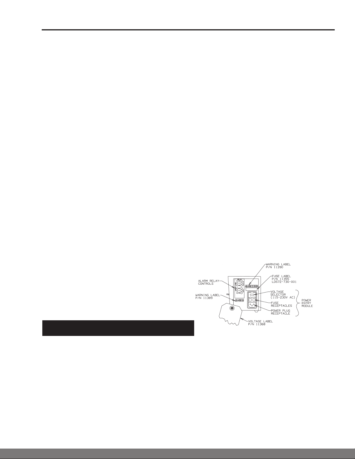
generator.) The voltage setting for the analyzer is shown through a small window on the power
entry module on the right side of the analyzer (see Figure 5). Check the voltage selector set-
ting prior to energizing the analyzer. The selector setting should match the voltage of the local
power supply. (Note: The "NA" version of the oxygen analyzer will only operate at 120 VAC.) Plug
the provided power cord into the power entry receptacle of the analyzer, and plug the opposite
end into a wall outlet with earth ground protection. The North American cordset is rated for 125V,
10 amperes, 18 AWG, SJT, with ferrite bead. Do not replace it with an inadequately rated cordset.
The analyzer is powered on by plugging into electrical supply. There is no power switch on
this product.
If the voltage selector displays an input power voltage different from the local power supply, it may
be changed using only a small screwdriver (check voltage rating of analyzer on product label on
the bottom panel to ensure compatibility with local electrical supply). First, use the screwdriver
to release the cover of the power entry module on the right side of the analyzer (see Figure 5).
Next, rotate the voltage selector until the desired input voltage is displayed in the window. Finally,
replace the power entry module cover.
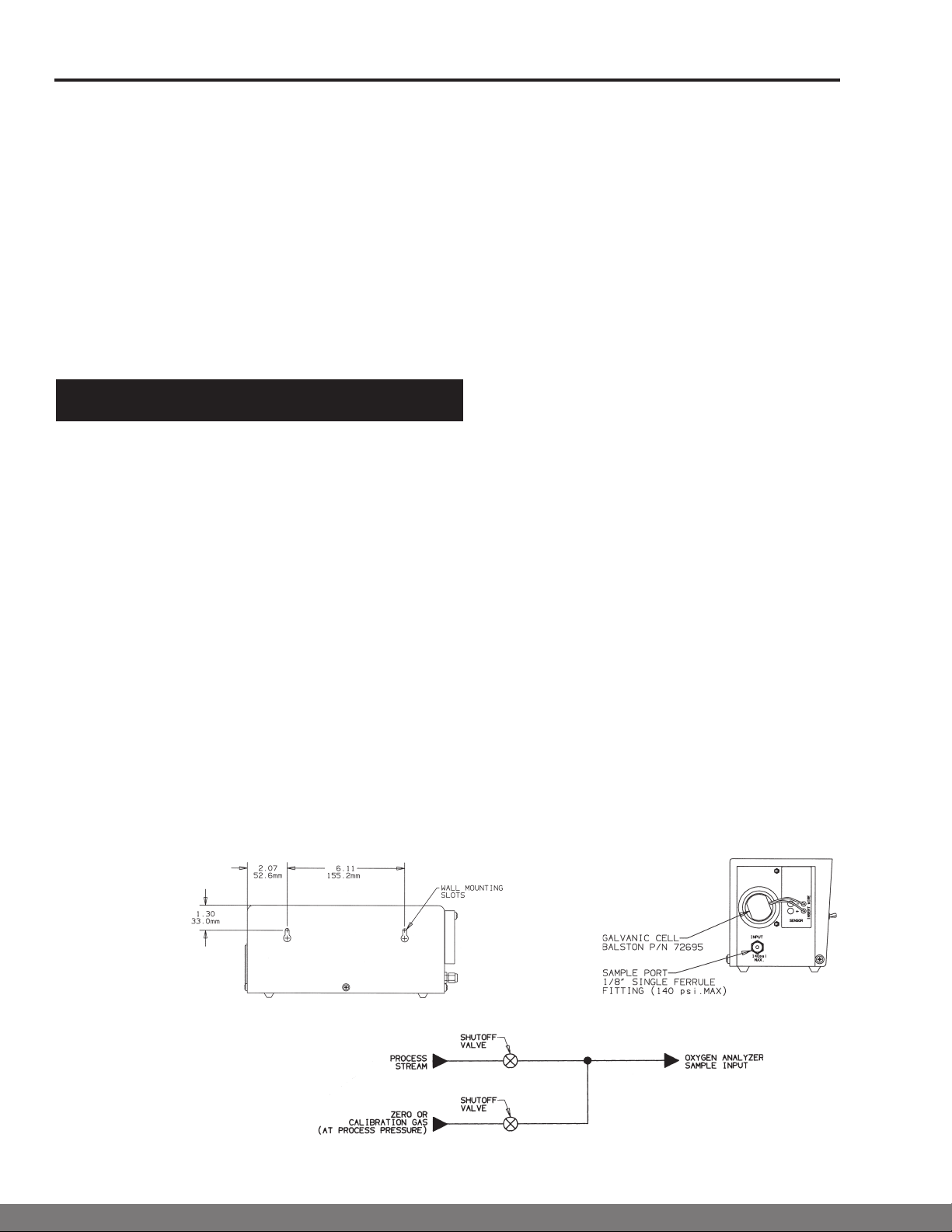
Galvanic Cell
Voltage Selector
The 72-730 and 72-O2730NA are calibrated prior to shipment; however, Parker strongly recom-
mends re-calibrating the units prior to initial start-up. After the initial start-up, the unit should be
calibrated on a bi-weekly basis until a suitable schedule is determined, based upon the level of
accuracy required by the application.
There are two methods of calibrating the 72-730 and 72-O2730NA Oxygen Analyzer: the two
point method and the single point method. In the two point method, the rst point in the
calibration range is set to zero using a zero gas (zero percent oxygen), and the second point in
the range is set to a known percentage of oxygen using a span gas (known quantity of oxygen,
per gas supplier) or compressed air (20.9% oxygen). In the single point method, only one point
in the calibration range is set, using either span gas or compressed air. Maximum accuracy in
oxygen concentration monitoring will be achieved if the oxygen concentration in the span gas is
within the range of the expected oxygen concentration in the process stream. See Figure 1 for
calibration controls and Figure 4 for recommended calibration gas valving.
Calibration
Operation
Figure 5 - Right Side View

Bulletin TI-72730J Installation, Operation and Maintenance Manual
72-730 and 72-O730NA Oxygen Analyzer
www.labgasgenerators.com
4
1-800-343-4048
4
1
CAUTION: The Balston 72-730 and 72-O2730NA Oxygen Analyzers will not provide accu-
rate readings unless calibrated on a regular basis. The procedure for the two point calibration
method is as follows:
1Isolate the 72-730 and 72-O2730NA by closing the valve between the process stream and
the analyzer (see Figure 4). Attach zero gas to port inlet.
2Open the valve in the line from the tank of zero gas to the analyzer (gas pressure should be
approximately equal to process pressure, if possible).
3Allow the zero gas to ow through the analyzer until the reading on the oxygen concentration
display stabilizes.
4Adjust the zero potentiometer until the oxygen concentration display reads zero.
5Disconnect the zero gas from the calibration gas line, and connect a tank of span gas (pro-
cess pressure) or a source of clean compressed air.
6Allow the reading to stabilize, and adjust the span potentiometer until the reading on the oxy-
gen concentration display reads the known percent (span gas) or 20.9% (compressed air).
7Close the valve from the calibration gas line and re-open the valve between the process
stream and the analyzer.
The procedure for the single point calibration method is as follows:
1Isolate the 72-730 and 72-O2730NA by closing the valve between the process stream and
the analyzer.
2Connect a tank of span gas (process pressure) or a source of clean compressed air to the
calibration gas line.
3Open the valve in the calibration gas line to introduce the span gas or compressed air to the
analyzer.
4Allow the gas or air to ow through the analyzer until the reading on the oxygen concentra-
tion display stabilizes.
5Adjust the span potentiometer until the reading on the oxygen concentration display reads
the known percent (span gas) or 20.9% (compressed air).
6Close the valve from the calibration gas line and re-open the valve between the process
stream and the analyzer.
(Note: Parker recommends the use of a span gas with an oxygen content between 1% and
10%.)
The high and low limits of the integral alarm may be set anywhere between 0.5% and 25%
oxygen, depending on the process limitations. To set the high alarm set point, press the alarm
set switch upward and simultaneously adjust the high potentiometer until the meter shows the
desired high alarm set point. To set the low alarm set point, press the alarm set switch downward
and simultaneously adjust the low potentiometer until the meter shows the desired low alarm set
point.
The Balston 72-730 and 72-O2730NA Oxygen Analyzers also include high and low alarm relay
contacts located on the right side panel (see Figure 5). The oxygen analyzer, through the use
of the alarm relay contacts, may be used to control the process stream or remotely activate an
alarm. For example, a high or low oxygen concentration could signal a remote alarm, open a
backup supply of the process stream, or close the process down for protection of downstream
equipment or processes. The alarm relay contacts should be wired (by a qualied electrician).
Both the high and low oxygen alarm conditions are provided with three relay outputs: a common
(C), a normally open (NO), and normally closed (NC).
The relay contacts are rated for 250 VAC, 5 amps resistive or 1 amp inductive load or
24 VDC 5 amps resistive or 1 amp inductive load. Do not exceed these values in order to
maintain the instrument safety certification.
To eliminate the possibility of electrical shock, disconnect the power cord before wiring the
alarm relay contacts to outside circuitry.
Alarm set points
Alarm relay contacts

Bulletin TI-72730J Installation, Operation and Maintenance Manual
72-730 and 72-O730NA Oxygen Analyzer
www.labgasgenerators.com
5
1-800-343-4048
All maintenance activities should be performed by suitable personnel using reasonable
care. Safety risks that may affect the service personnel are identified with protective
measures that apply. The service personnel will verify the safe state of the analyzer
after maintenance is completed.
The only routine maintenance required by the Balston 72-730 and 72-O2730NA Oxygen
Analyzers is timely calibration and annual sensor replacement. Calibration details and rec-
ommended calibration scheduling are outlined in the “Calibration” section of this manual. If
necessary, the Balston 72-730 and 72-O2730NA Oxygen Analyzer may be wiped clean with a
dry cloth on an as needed basis. Do not use water, aerosols, or other cleaning agents to
clean the unit.
Note: There are no customer serviceable parts inside the metal cover of the analyzer.
Disconnect analyzer from power supply before replacing galvanic cell sensor.
The galvanic cell sensor degrades over time and should be replaced on an annual basis
(P/N 72695). The only tools needed for this replacement are a small screwdriver and wire
strippers. The procedure for changing the sensor is outlined below and takes approximately
10 minutes.
1 Remove sensor cover and disconnect old cell wires from connectors by pressing the
screwdriver into the hole next to the connector and pulling wires out.
2 Strip replacement sensor connecting wires to 1/4" to 3/8" (6mm to 9mm) using wire
strippers. Install the sensor into the sensor holder on the left side panel of the analyzer
(see Figure 3) by pushing rmly into place.
3Insert small screwdriver into the hole adjacent to the wire connection point (see Figure 3)
and press to open connector.
4Slide the stripped wire end into the appropriate (red or black) connection port until it
“bottoms out”. The red wire goes to the “+” connector, and the black wire goes to the
“-” connector.
5Remove the screwdriver to clamp the wire into the connection port. Pull the wire gently
Maintenance
Galvanic Cell
Replacement
The customer is responsible for the circuitry utilizing these relay outputs and should use good
engineering safety practices in the design of this circuitry.
1 Strip all connecting wires to 1/4" to 3/8" (6mm to 9mm) using wire strippers.
2 Insert small screwdriver into the hole adjacent to the wire connection point and press to
open connector.
3 Slide the stripped wire end into the connection port until it “bottoms out”.
4 Remove the screwdriver to clamp the wire into the connection port. Pull the wire gently to
test integrity of the connection. Repeat this procedure from step 2 if the wires release easily.
Figure 6 - Sample Schematic for Wiring Alarm Relay Contacts, Right Side View

Bulletin TI-72730J Installation, Operation and Maintenance Manual
72-730 and 72-O730NA Oxygen Analyzer
www.labgasgenerators.com
6
1-800-343-4048
Description P/N
Sensor seal set 22172
Galvanic cell (sensor) 72695
Fuse 13221
Cordset 13612
Balston 72-730 and 72-O2730NA Oxygen Analyzer
CSA Certification Standard CSA 22.2 No. 61010-1-12
IEC 61010 Installation Category Category II
IEC 61010 Pollution Category Degree 2
Accuracy ±1% Full scale calibrated span, after 30 min. stabilization
Span concentration .1 to 99.9% oxygen
Response time 12 seconds
Display LED Type
Digital display range 00.0 to 99.9% oxygen
Min./Max. sample flow rate 25 scc/min. to 850 scc/min.
Min./Max. inlet pressure 2 psig/140 psig (0.1 barg/9.7 barg)
Min./Max. operating temperatures 59°F / 95°F (15°C / 35°C)
Max. Relative Humidity 80% to 31°C; 50% at 40°C
Altitude 2000 m
Sensor type Galvanic cell
Sensor life 1 year
Required calibration frequency 2 weeks
Alarm outputs DPDT relay contacts 3 amp, 250 VAC Rating, resistive
Power requirement* 120 VAC, 230 VAC, 50/60 Hz, .10 A (120 VAC), .05 A (230 VAC)
Fuse Type Type T, Slow Blo Fuse, 250 V, 0.10 amp, 5 x 20 mm
Physical dimensions 11"h x 5"w x 4"d (28cm x 13cm x 11cm)
Shipping weight 6.5 lbs. (3 kg)
*Note: Main supply line voltage must be within 10% of nominal rated voltage for the generator.
System Specifications
2
3
Fuse
Replacement
to test integrity of the connection. Repeat this procedure from step 2 if the wires release
easily. Replace sensor cover.
This equipment has fuses in both neutral and phase lines. Use care when servicing.
Occasionally, one or both of the fuses in the analyzer may burn out. The fuses are located
in the power receptacle on the left hand side of the analyzer. Before servicing the fuses,
disconnect the power cord from the local power supply and from the power entry mod-
ule. Both fuses should be checked each time fuse replacement is warranted. To access the
fuses, use a small screwdriver to remove the holder located in the power receptacle of the
generator (see Figure 5). Replace either one or both fuses as necessary and re-assemble.
For continued protection against risk of fire, replace only with fuse of specified rating.
Replacement Parts

Bulletin TI-72730J Installation, Operation and Maintenance Manual
72-730 and 72-O730NA Oxygen Analyzer
www.labgasgenerators.com
7
1-800-343-4048
Problem Possible Cause
No display/reading Sensor wires not connected; check wire strip length, polarity.
Display varies Check process; check sensor light; check sample lines for
leaks
Alarm stays on Check set points
Limited range during calibration Replace sensor (P/N 72695)
Troubleshooting
Don’t Forget To:
Serial Numbers
1Complete and mail or fax in your warranty registration card
2Keep your product certication in a safe place.
3Call the Technical Services Department at 800-343-4048, 8AM to 5PM Eastern Time
with any questions (North America only). For other locations, please contact your local
representative.
The serial number for the unit is located on the bottom panel. For your own records, and in
case service is required, please record the following:
DATE IN SERVICE SERIAL NO.
Please have the serial number available when calling for assistance.
WARRANTY (NORTH AMERICA ONLY)
(FOR INFORMATION CONTACT YOUR LOCAL REPRESENTATIVE)
Parker Hannin guarantees to the original purchaser of this product, that if the product fails or is defective
within 12 months from the date of purchase, when this product is operated and maintained according
to the instructions provided with the product, then Parker guarantees, at Parker’s option, to replace the
product, repair the product, or refund the original price for the product. This warranty applies only to
defects in material or workmanship and does not cover: ring and valve wear on compressors, routine
maintenance recommended by the instructions provided with this product, or lter cartridges. Any
modication of the product without written approval from Parker will result in voiding this warranty.
Complete details of the warranty are available on request. This warranty applies to units purchased
and operated in North America.

Bulletin TI-72730J Installation, Operation and Maintenance Manual
72-730 and 72-O730NA Oxygen Analyzer
www.labgasgenerators.com
8
1-800-343-4048
Parker Hannin Manufacturing Limited
Gas Separation and Filtration Division EMEA
Dukesway, Team Valley Trading Estate
Gateshead, Tyne and Wear, Angleterre NE11 0PZ
Tél. : +44 (0)191 402 9000 Fax : + 44 (0)191 482 6296
www.parker.com/gsfe FNSdhFNS_TSG@parker.com
Parker Hannin Corporation
Industrial Gas Filtration and
Generation Division
4087 Walden Ave.
Lancaster, NY 14086
Tel: 978-858-0505 Fax: 978-478-2501
www.labgasgenerators.com
!
Symbol Description
Caution, refer to accompanying
documents for explanation.
Refer to the caution/warning note
indicated for explanation.
Caution, risk of electric shock.
3
!
Copyright © Parker Hannin Corporation 1995, 2015
Printed in U.S.A. Bulletin TI-72730J
CELL: SPE
•
R
E
C
Y
C
L
A
B
L
E
•
R
E
C
Y
C
L
A
B
L
E
•
R
E
C
Y
C
L
A
B
L
E
This manual suits for next models
1
Table of contents
Other Parker Test Equipment manuals
Popular Test Equipment manuals by other brands

Swan Analytical Instruments
Swan Analytical Instruments Chematest 30 Operator's manual

EEC
EEC ESD-140 Operation manual

Compliance West
Compliance West CDT-240 CALIBRATION PROCEDURE

GW Instek
GW Instek GOS-6200 manual

Bacharach
Bacharach INJECTOR CALIBRATOR CD3 Installation & operation instruction

SmartSafe
SmartSafe iSmartEV OM210 user manual