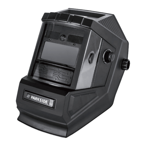
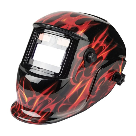
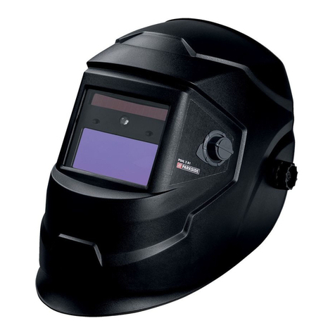
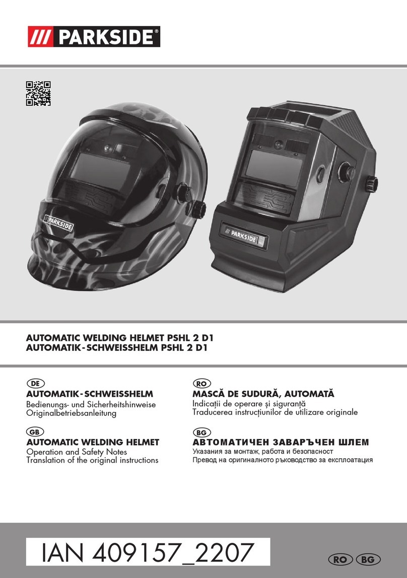
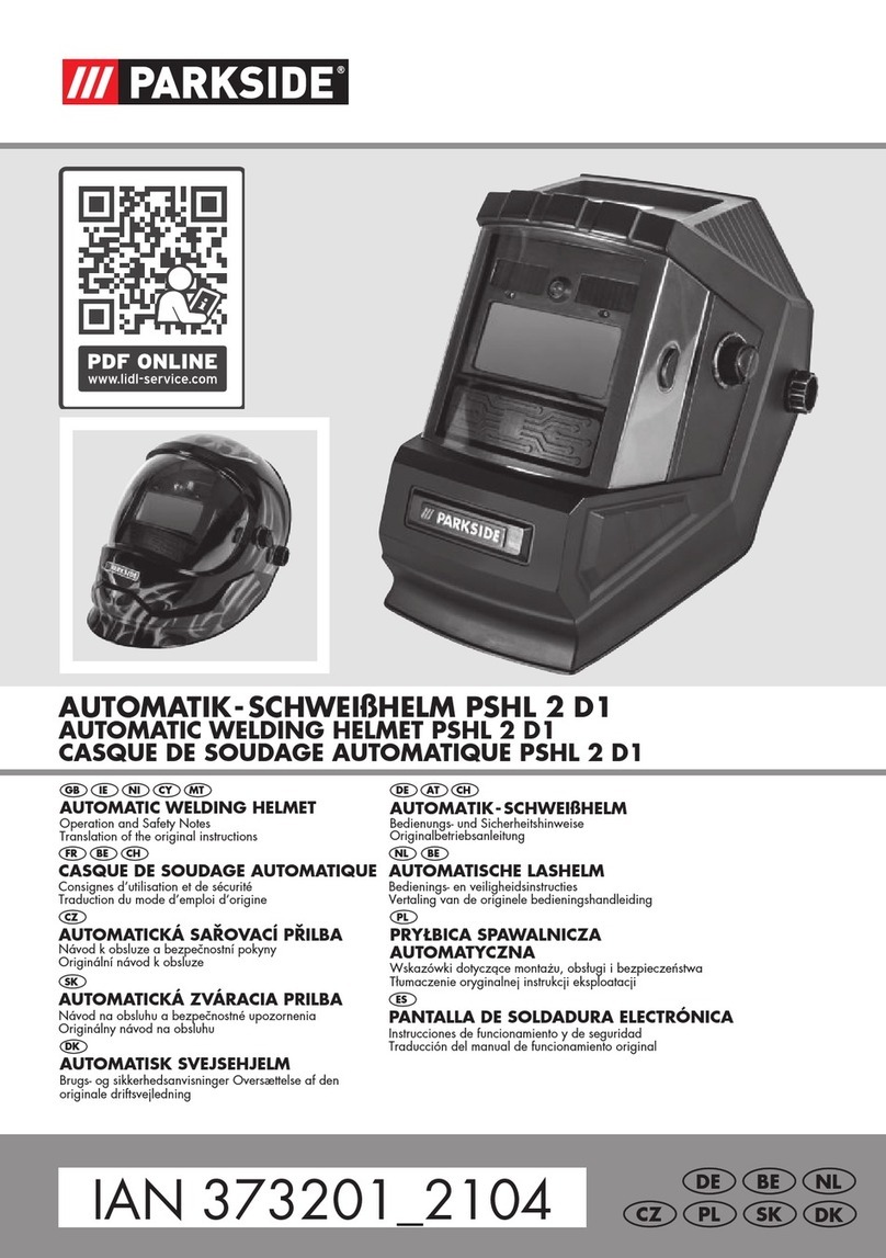
Parkside PSHL 2 A1 User manual

PDF
ONLINE
www.lidl-service.com
AUTOMATIK-SCHWEIßHELM PSHL 2 A1
DE AT CH
AUTOMATIK-SCHWEIßHELM
Montage-, Bedienungs- und Sicherheitshinweise
Originalbetriebsanleitung
IAN 286805 DE AT
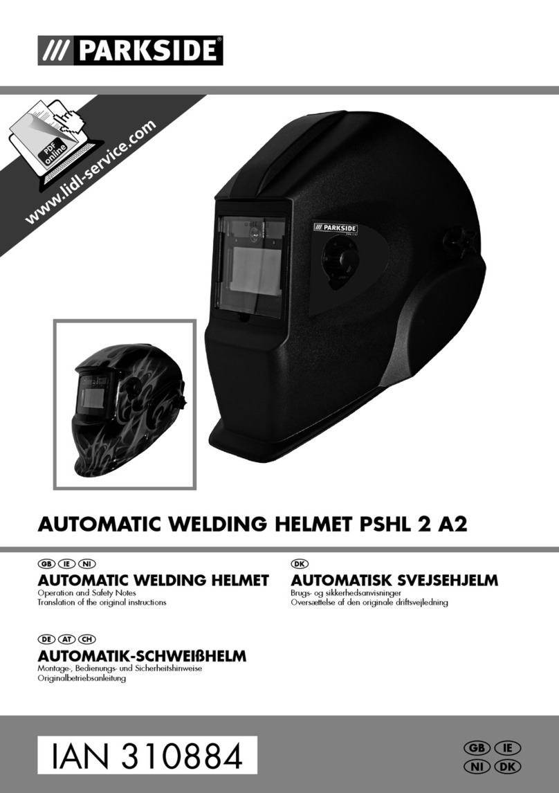
AUTO-DARKENING WELDING HELMET PSHL 2 A1
NL
GB IE NI
FR
BE
DK
DE
AUTOMATISCHE LASHELM
Bedienings- en veiligheidsinstructies
Vertaling van de originele bedieningshandleiding
AUTO-DARKENING WELDING HELMET
Operation and Safety Notes
Translation of the original instructions
MASQUE DE SOUDEUR AUTOMATIQUE
Consignes d’utilisation et de sécurité
Traduction du mode d’emploi d‘origine
AUTOMATISCHE LASHELM
Bedienings- en veiligheidsinstructies
Vertaling van de originele bedieningshandleiding
AUTOMATISK SVEJSEHJELM
Brugs- og sikkerhedsanvisninger
Oversættelse af den originale driftsvejledning
AUTOMATIK-SCHWEIßHELM
Montage-, Bedienungs- und Sicherheitshinweise
Originalbetriebsanleitung
IAN 286805 NIGB
FRNL
DKIE
DEBE

GB IE NI
DK
NL
BE
FR
DE
Before reading, unfold the page containing the illustrations and familiarise yourself with all functions of
the device.
Før du læser, vend siden med billeder frem og bliv bekendt med alle apparatets funktioner.
Klap, voordat u begint te lezen, de pagina met afbeeldingen uit en maak u aansluitend vertrouwd met
alle functies van dit apparaat.
Klap, voordat u begint te lezen, de pagina met afbeeldingen uit en maak u aansluitend vertrouwd met
alle functies van dit apparaat.
Avant de lire le document, allez à la page avec les illustrations et étudiez toutes les fonctions de l’appareil.
Klappen Sie vor dem Lesen die Seite mit den Abbildungen aus und machen Sie sich anschließend mit
allen Funktionen des Gerätes vertraut.
GB / IE / NI Operation and Safety Notes Page 5
DK Brugs- og sikkerhedsanvisninger Side 15
NL Bedienings- en veiligheidsinstructies Pagina 25
BE Bedienings- en veiligheidsinstructies Pagina 35
FR Consignes d’utilisation et de sécurité Page 45
DE Montage-, Bedienungs-, und Sicherheitshinweise Seite 55


Table of contents
GB/IE/NI 5
List of pictograms used..................................................................................Page 6
Introduction.........................................................................................................Page 6
Intended use .............................................................................................................Page 6
Parts Description .......................................................................................................Page 6
Technical Data ..........................................................................................................Page 7
Scope of delivery ......................................................................................................Page 7
Safety instructions............................................................................................Page 7
Initial use..............................................................................................................Page 9
Cleaning and Maintenance..........................................................................Page 10
Environmental instructions and disposal information....................Page 10
Troubleshooting.................................................................................................Page 11
Warranty and service information ..........................................................Page 11
Warranty terms .........................................................................................................Page 11
Extent of warranty......................................................................................................Page 11
Processing of warranty claims .....................................................................................Page 12
Service.....................................................................................................................Page 12
Label meanings .................................................................................................Page 12
EU Conformity Declaration...........................................................................Page 13

GB/IE/NI6
Auto-Darkening Welding
Helmet PSHL 2 A1
Introduction
Congratulations! You have chosen a
high-quality product from our
company. Familiarise yourself with the product
before using it for the first time. In addition, please
carefully refer to the instructions for use and the
safety instructions below.
KEEP OUT OF THE REACH OF CHILDREN!
Intended use
This welding helmet protects the eyes and face from
sparks, splashes and UV rays while welding and
automatically adapts to the lighting conditions. It
ensures an immediate, sensor-controlled darkening
upon arc ignition as well as automatic illumination
at the end of the welding procedure (including
a short delay to protect against afterglow). This
welding helmet provides a freely adjustable DIN
protection level with a lateral adjustment wheel and
is also adjustable for flying sparks during grinding
work. Only use the product as described and
for its indicated purpose. Keep these instructions
in a safe place. When passing this product on
to others, please also include all the documents.
Any use other than the intended is prohibited and
potentially dangerous. Damages resulting from
noncompliance or misuse are not covered by the
warranty and are not included in the manufacturer‘s
liability. This device has been designed for house-
hold use and may not be used for commercial or
industrial purposes.
Parts Description
Viewing pane
Helmet casing
Solar cell
Rear pane
Headband
Adjustable headband button
Adjustable headband buttons
UV filter
Darkening regulator
Test button
Delay setting
Sensitivity setting
Low battery display
LED Lighting switch
Battery compartment
Bracket
List of pictograms used / Introduction
List of pictograms used
Caution!
Read instructions for use! Attention, potential dangers!
Do not dispose of electrical
equipment in household waste! Important notice!
Attention: The welding helmet does
not provide any eye, ear or face
protection!
Warning: arc rays can injure the
eye's retinas!
2
1
3
4
5
6
7
8
9
10
11
12
13
14
15
16

GB/IE/NI 7
Introduction/ Safety instructions
Technical Data
Filter cartridge size: 110 x 90 x 10 mm
Field of vision: 9.2 x 4.2 cm
Bright state: DIN 4
Dark state: DIN 9–DIN 13
Switching times
Bright to dark: 0.23~0.72 ms
Dark to bright: 0.15~0.45 s
Switch on / off: Fully automatic
Energy supply: Solar cell
UV / IR protection: DIN 16
Operating temperature: -5 °C to +55 °C
Storage temperature: -20 °C to + 70 °C
Welding procedure: MMA, MIG, MAG,
TIG, plasma cutting and
plasma welding
Maximum service life: approx. 6 years
Scope of delivery
1 Auto-Darkening Welding Helmet
1 Set of instructions for use
Safety instructions
Please carefully read the instructions
for use and follow the specified
notices. Familiarise yourself with the
equipment, its proper use and the
safety notices using these instructions
for use. All technical data about
this welding helmet is on the label,
please learn about this product‘s
technical facts.
This device may be used by
children aged 16 years and up, as
well as by persons with reduced
physical, sensory or mental
capacities, or lacking experience
and / or knowledge, so long as
they are supervised or instructed
in the safe use of the device and
understand the associated risks. Do
not allow children to play with the
product. Cleaning and user main-
tenance should not be performed
by children without supervision.
The welding helmet with auto-
matic darkening is not suitable
for laser and gas welding.
Never place the welding helmet
on hot surfaces.
Never open the welding helmet.
Never carry out repairs on or
modifications to the welding
helmet. These may only be
carried out by trained experts.
Please ensure that you have set
the automatic darkening before
each welding procedure.
The safety visor should not be
opened. It protects the filter from
dirt and damage.
If the filter does not automatically
darken, then immediately end the
welding procedure and contact
the manufacturer.
Only use the welding helmet in
temperatures between -5 °C and
+55 °C. The filter‘s reaction time
will slow down if this tempera-
ture has not been reached or is
exceeded.
GB/IE/NI8
Safety instructions
Clean the filter, the surface of
the helmet and the solar cells
regularly.
Replace the protective visor if
scratches or damages appear.
The welding helmet does not
provide protection against impact.
Frequent use, cleaning or storage
can mean that the service life is
less than 6 years. Replace the
welding helmet immediately if
the viewing panel gets scratched
or the viewing panel is visibly
damaged in any other way.
ATTENTION! Materials that
come into contact with the wearer‘s
skin may cause allergic reactions in
people with sensitive skin.
ATTENTION! Eye protection
can represent a hazard for the
wearer if it is worn over normal
corrective glasses due to the impact
from high-speed particles.
ATTENTION! If protection
against high-speed particles at
extreme temperatures is required, the
eye protection chosen must be
labelled with the letter T directly after
the letter for the impact intensity,
i. e. FT, BT or AT. If the letter for the
impact intensity is not followed by the
letter T, the eye protection may only
be used against high-speed particles
at room temperature.

GB/IE/NI 9
Initial use
Initial use
Note: Only use the welding helmet with the rear
pane mounted
4
.
Note: Keep the UV filter‘s sensors
8
clean and
clear.
Check that the welding helmet and the
protective screen are intact before each use.
If the protective screen has scratches, cracks or
irregularities, it must be replaced before use,
as serious injuries may occur otherwise.
Remove the protective film from the inside and
the outside of the visor.
Put on the welding helmet with the help of the
headband
5
. Press the adjustment buttons
6
to make the welding helmet tighter and
the adjustment button
7
, to fix the welding
helmet. When adjusting, ensure that your head
is placed as far into the helmet as possible and
that it sits as close as possible to your face.
Set the appropriate darkening shade before
the welding procedure (see the following
table). The darkening shade may be manually
adjusted from 9 to 13 by twisting the darken-
ing regulator
9
on the outside of the helmet.
ATTENTION! The darkening regulator
9
has the setting position “grind“. If the darkening
regulator
9
is set to this position the automatic
darkening is deactivated.
Only use this setting when you do not wish to use
the welding helmet for welding. The automatic
darkening is then no longer active.
Check the light density before each use.
Test procedure: Bring the viewing panel closer
to an external light source with a value of more
than 40 W and examine whether or not the
screen darkens or illuminates. To do so, turn the
darkening control
9
clockwise from "Grind"
to the next position. This sets the filter to
auto-darkening mode. If you turn the darkening
control
9
anticlockwise back to "Grind", the
filter's auto-darkening feature is once again
deactivated.
To replace the UV filter/solar cell, press the lock-
ing lugs on both sides of the filter outwards (see
figure B). Then use a finger to lift the filter at the
notch at the top of the filter. (Variant: Black)
Arc current (ampere)
1,5 6 10 15 30 40 60 70 100 125 150 175 200 225 250 300 350 400 450 500 600
SMAW 8 9 10 11 12 13 14
MAG 8 9 10 11 12 13 14
TIG /
GTAW 8 9 10 11 12 13
MIG
(heavy) 9 10 11 12 13 14
MIG
(light) 10 11 12 13 14
PAC 9 10 11 12 13
PAW 4 5 6 7 8 9 10 11 12
Table for setting the darkening shades
SMAW: welding with coated electrodes
MIG (heavy): MIG welding heavy metals
MIG (light): MIG welding light metals
and alloys
TIG / GTAW: welding with inert gases
MAG: welding with metal active gass
PAC: plasma cutting
PAW: plasma welding

GB/IE/NI10
To replace the UV filter/solar cell, pull the
bracket
16
at the bottom edge of the filter over
the two protruding locking pins and outwards
(see figure C). Flip the bracket upwards (see
figure D). With your thumbs centred under-
neath the filter, lift the filter and pull it down to
remove it. (Variant: With flames)
You can use the test button
10
to check
whether the welding helmet's darkening feature
is working properly.
You can adjust the delay setting
11
to
configure whether or not the auto-darkening
feature should be switched off immediately
after stopping welding work, depending on the
type of welding work. At the lowest setting,
auto-darkening is switched off immediate-
ly. Turn the rotary switch clockwise towards
the highest setting to prolong the time the
auto-darkening feature remains active after
welding work. This feature is very useful for
handling afterglow.
You can use the sensitivity setting
12
to adjust
the light sensitivity of the sensor. With low in-
cident light, the control can be adjusted to the
highest setting to ensure that the auto-darken-
ing feature is activated even for a weak light
source. Even with this additional feature, you
can also adjust the light sensitivity of the sensor
to suit your own personal requirements.
The lowlight sensor switches the LED lamp on
in dark environments and off in brightly lit
environments. This helps to illuminate the object
being welded in dark working conditions. The
LED lamp can be switched on and off using the
lamp control
14
. If the battery charge level is
too low, you can replace the batteries. To do
so, slide the left side of the battery compart-
ment
15
to the left (see figure A). A low battery
charge level is indicated with a red warning
light on the display
13
.
Cleaning and Maintenance
Do not use any harsh cleaning agents to clean
the helmet casing
2
.
Never bring the UV filter
8
into contact with
water.
Clean the product with a soft, dry cloth, with
a cloth dampened with pure alcohol or with a
cloth dampened with disinfectant.
Environmental instructions
and disposal information
Don‘t waste, recycle!
The device, accessories and packaging should be
recycled in an environmentally friendly manner.
Do not throw the auto-darkening welding helmet
into household rubbish, fire or water. If possible,
non-operational equipment should be recycled.
Contact your local retailer for information.
... / Cleaning and Maintenance / Environmental instructions and disposal ...

GB/IE/NI 11
Troubleshooting / Warranty and service information
Troubleshooting
Error Cause Solution
The filter does not darken in a
normal way or flickers.
The protector does not darken in a
normal way or flickers.
Clean the protector or replace it.
The arc sensor is not clear. Clean the arc sensor's surface.
The welding current is too low. Set the sensitivity to the maximum
degree.
The reaction is slow. The ambient temperature is too
low / high.
Only use the welding helmet in
temperatures between -5 °C and
+55 °C.
The sensitivity is too low. Set the sensitivity to a higher
setting.
The visibility is poor. The protector / the protective
screen is dirty.
Clean the protector and the
protective screen.
The protective film on the protective
screen was not removed.
Remove the protective film.
The ambient light is not sufficient. Apply more light to your work
surroundings.
The wrong darkening shade has
been set.
Reset the darkening shade.
The welding helmet slips. The headband
5
has been put on
incorrectly.
Put on the headband
5
again
tighter.
Warranty and service
information
Creative Marketing Consulting GmbH
warranty
Dear customer, the warranty for this device is
3 years from the date of purchase. In the event of
product defects, you have legal rights against the
retailer of this product. Your statutory rights are
not limited in any way by our warranty detailed
below.
Warranty terms
The warranty period begins on the date of pur-
chase. Please keep the original receipt in a safe
place. This document is required as your proof of
purchase. Should this device show any fault in
materials or manufacture within 3 years from the
date of purchase, it will be repaired or replaced –
at our choice – by us free of charge. This warranty
is conditional on the defective device and the
receipt of purchase being presented within the
3 year warranty period, and that there is a brief
written description of the nature of the defect and
of the date it arose.
If the defect is covered by our warranty, you will
receive the product which has been repaired or a
new product. A repair or exchange of the device
does not begin a new warranty period.
Extent of warranty
The appliance has been manufactured to strict
quality guidelines and meticulously examined
before delivery.

GB/IE/NI12
Warranty and service information / Label meanings
The warranty applies to defects in material or
manufacture. This warranty does not apply to
product parts subject to normal wear and tear
and which can therefore be considered as wear
items, or to damage to fragile parts, e.g. switches,
storage batteries or glass parts.
This warranty becomes void if the device has been
damaged or improperly used or maintained.
All instructions provided in the instructions for use
must be followed strictly to constitute proper use
of the product. Purposes and practices which the
operating instructions warn of or advise against
must be avoided without fail.
This product is intended for private, non-commercial
use only. Any incorrect or improper use of the de-
vice, use of force and changes not performed by our
authorized service branch will void the warranty.
Processing of warranty
claims
Please follow the instructions below to ensure your
claim is processed quickly:
When inquiring about your product please have
your receipt and product number (e.g. IAN) ready
as your proof of purchase.
The product number can be found on the type
plate, an engraving, the cover page of your
instructions (bottom left) or the decal at the back
or bottom. In the event of malfunctions or other
defects, please first contact the service department
below by phone or e-mail.
A product recorded as defective, along with the
proof of purchase (sales receipt) and a description
of the defect and when it occurred, can then be re-
turned free of charge to you to the service address
provided.
Note:
On www.lidl-service.com you can download
this as well as many other manuals, product
videos and software.
Service
Only use original accessory parts:
Viewing pane 109.9 mm x 85.8 mm
Rear pane 98.3 mm x 45.9 mm.
How to contact us:
GB, IE, NI
Name: C. M. C. GmbH
Website: www.cmc-creative.de
E-mail: ser[email protected]
Phone: 0-808-189-0652
Registered office: Germany
IAN 286805
Please note that the following address is not a
service address. Please first contact the service
point named above.
Address:
C. M. C. GmbH
Katharina-Loth-Str. 15
DE-66386 St. Ingbert
DEUTSCHLAND
Ordering spare parts:
www.lidl.com/contact-us
Label meanings
Safety viewing panels approved
according to DIN EN 166: CMC 1 F CE
Legend:
CMC = manufacturer code
1 = optical class
F = low power shock
CE = CE symbol)

GB/IE/NI 13
Label meanings / EU Conformity Declaration
ADF approved according to DIN EN 379:
Legend:
4 = bright state
9–13 = dark state
CMC = manufacturer code
number 1 = optical class
number 2 = scattered light grade
number 3 = homo-geneity class
number 4 = angle dependency class
379 = test standard
CE = CE symbol
Welding helmet case
Manufacturer identification: CMC GmbH
Number of the standard: EN 175
Area(s) of application (if required): S, F, B
Mass in grams (if required)
Symbol Protection
type
Description of
scope
of application
S increased
strength
Mechanical strength
-F Low
energy
impact
Mechanical strength
-B Medium
energy
impact
Mechanical strength
If the symbols F, B and A are not obtained for
the viewing panel as well as the supporting body,
the entire eye protection device is to be conferred
with a lower rating.
Certification body:
DIN CERTCO Gesellschaft für
Konformitätsbewertung mbH
Alboinstrasse 56
12103 Berlin
Notified body number 0196
EU Conformity Declaration
We,
C. M. C. GmbH
Responsible for documentation: Mark Uhle
Katharina-Loth-Str. 15
66386 St. Ingbert
Germany
declare in our sole responsibility the product
Auto-Darkening Welding Helmet
IAN: 286805
Series number: 2093 / 2094
Year of manufacture: 2018/15
Model: PSHL 2 A1
meets the basic safety requirements of European
Directives
EC Electromagnetic Compatibility Directive
2014 / 30 / EU
RoHS Directive
2011 / 65 / EU
Personal Protective Equipment Directive
89 / 686 / EEC
and its amendments.
The conformity assessment is based on the
following harmonised standards:
EN 379:2009-07
EN 175:1997-08
EN 166:2002-04
St. Ingbert, 12.12.17
ppa. Marc Uhle – Documentation Officer

GB/IE/NI14

Indholdsfortegnelse
DK 15
Symbolforklaring .............................................................................................Side 16
Indledning............................................................................................................Side 16
Formålsbestemt anvendelse.........................................................................................Side 16
Beskrivelse af de enkelte dele .....................................................................................Side 16
Tekniske data ............................................................................................................Side 17
Leveringsomfang .......................................................................................................Side 17
Sikkerhedshenvisninger................................................................................Side 17
Ibrugtagning.......................................................................................................Side 19
Rensning og vedligehold..............................................................................Side 20
Miljøhenvisninger og oplysninger vedrørende bortskafning.....Side 20
Afhjælpning af fejl...........................................................................................Side 21
Oplysninger om garanti og serviceafvikling......................................Side 21
Garantibetingelser.....................................................................................................Side 21
Garantiens omfang....................................................................................................Side 21
Afvikling af garantisager ............................................................................................Side 22
Service.....................................................................................................................Side 22
Mærkningens betydning...............................................................................Side 22
EF-konformitetserklæring.............................................................................Side 23

DK16
Automatisk svejsehjelm
PSHL 2 A1
Indledning
Hjerteligt tillykke! Du har valgt et
kvalitetsprodukt fra vort firma.
Lær apparatet at kende inden første ibrugtagning.
Læs hertil opmærksomt den følgende brugsvejled-
ning og sikkerhedshenvisningerne.
OPBEVARES UTILGÆNGELIGT FOR BØRN!
Formålsbestemt anvendelse
Ved svejsningen beskytter denne svejsehjelm øjne
og ansigt mod gnister, sprøjt og uv-stråling, og den
tilpasser sig automatisk til lysforholdene. Den sør-
ger for en omgående, sensorstyret nedblænding,
når lysbuen tændes, og den blænder automatisk
op igen ved svejseprocedurens afslutning (inklusive
en kort forsinkelse som beskyttelse mod efterglød).
Svejsehjelmen har et trinløst justerbart DIN-
beskyttelsesniveau med drejeknap i siden, og den
kan også indstilles til gnistregn ved slibearbejde.
Anvend produktet udelukkende som beskrevet og
til de oplyste anvendelsesområder. Opbevar denne
vejledning omhyggeligt. Giv venligst også alle
disse papirer videre, hvis produktet gives videre.
Enhver brug, der afviger fra den formålsbestemte
anvendelse, er ikke tilladt og potentielt farlig. Farer
på grund af manglende hensyntagen hertil eller
på grund af forkert brug dækkes ikke af garantien
og ligger uden for fabrikantens ansvarsområde.
Apparatet blev konstrueret til privat brug og må
ikke anvendes i erhvervsmæssige eller industrielle
sammenhænge.
Beskrivelse af
de enkelte dele
Udvendigt beskyttelsesglas
Hjelmens skal
Solcelle
Indvendigt beskyttelsesglas
Hovedtøj
Indstillingsknap til hovedtøj
Indstillingsknapper til hovedtøj
UV-filter
Nedblændingsknap
Testknap
Forsinkelsesindstilling
Følsomhedsindstilling
Batteriniveauindikator
Knap til lysdiode-belysning
Batterirum
Bøjle
Symbolforklaring / Indledning
Symbolforklaring
Pas på!
Læs driftsvejledningen! Pas på, mulige farer!
Bortskaf ikke elektriske apparater
sammen med husholdningsaffaldet! Vigtig oplysning!
Pas på: Svejsehjelme giver
ikke nogen beskyttelse for øjne,
ører og ansigt!
Pas på: Lysbuestråler
kan skade øjets nethinde!
2
1
3
4
5
6
7
8
9
10
11
12
13
14
15
16

DK 17
Indledning / Sikkerhedshenvisninger
Tekniske data
Filterkassettens størrelse: 110 x 90 x 10 mm
Synsfelt: 9,2 x 4,2 cm
Lys tilstand: DIN 4
Mørk tilstand: DIN 9–DIN 13
Skiftetider
Fra lys til mørk: 0,23~0,72 ms
Fra mørk til lys: 0,15~0,45 s
Tænd / sluk: Fuldautomatisk
Energiforsyning: Solcelle
UV- / IR-beskyttelse: DIN 16
Driftstemperatur: -5 °C til + 55 °C
Opbevaringstemperatur: -20 °C til + 70 °C
Svejseformer: MMA, MIG, MAG, TIG,
plasmaskæring
og plasmasvejsning
Maksimal levetid: ca. 6 år
Leveringsomfang
1 automatisk svejsehjelm
1 betjeningsvejledning
Sikkerhedshenvisninger
Læs venligst brugsvejledningen
grundigt igennem, og tag hensyn
til de beskrevne henvisninger. Lær
ved hjælp af denne brugsvejledning
apparatet og dets rigtige brug at
kende og læs alle sikkerhedshen-
visningerne. På typeskiltet står alle
tekniske data for denne svejsehjelm.
Informer dig venligst om dette
produkts tekniske forhold.
Dette apparat kan benyttes
af børn fra 16-års alderen og
opefter samt af personer med
forringede fysiske, sensoriske eller
mentale evner eller med mangel
på erfaring og viden, når de er
under opsyn eller mht. sikker brug
af apparatet er blevet vejledt og
har forstået de deraf resulterende
farer. Børn må ikke lege med
apparatet. Rengøring og vedlige-
holdelse fra brugerens side må
ikke gennemføres af børn uden
at være under opsyn.
Svejsehjelmen med automatisk
nedblænding er ikke egnet til
laser- og autogensvejsning.
Læg aldrig svejsehjelmen på
varme overflader.
Åbn aldrig svejsehjelmen. Foretag
ikke nogen reparationer eller
ændringer på svejsehjelmen.
Dette må kun gennemføres af
uddannet fagpersonale.
Pas på, at du har indstillet den
automatiske nedblænding før
ethvert svejsearbejde.
Sikkerhedsvisiret må ikke åbnes.
Det beskytter filteret imod snavs
og beskadigelse.
Hvis filteret ikke blænder ned
automatisk, skal du straks stoppe
med at svejse og kontakte
fabrikanten.
Benyt svejsehjelmen kun ved
temperaturer mellem -5 °C og
+ 55 °C.

DK18
Sikkerhedshenvisninger
Filtret reagerer langsommere,
hvis disse temperaturer under- /
overskrides.
Rens filtret, hjelmens overflade og
solcellerne regelmæssigt.
Udskift beskyttelsesvisiret, hvis det
har ridser eller er beskadiget.
Svejsehjelmen beskytter ikke imod
stød.
Brug, rensning og opbevaring
kan reducere levetiden på 6 år.
Ved ridser i det udvendige
beskyttelsesglas eller ved andre
synlige skader skal glasset hhv.
svejsehjelmen straks udskiftes.
PAS PÅ! Materialer, som
kommer i kontakt med brugerens
hud, kan hos følsomme personer
fremkalde allergiske reaktioner.
PAS PÅ! Udstyr til beskyttelse
af øjnene kan ved dele med høj
hastighed udgøre en fare for bruge-
ren, hvis det bæres over gængse
korrektionsbriller, idet der kan
overføres stød.
PAS PÅ! Hvis en beskyttelse
mod dele med høj hastighed ved
ekstreme temperaturer er nødvendig,
skal det valgte udstyr til beskyttelse af
øjnene være mærket med bogstavet T
direkte efter bogstavet for kollisionsin-
tensiteten, dvs. FT, BT eller AT.
Når bogstavet T ikke følger efter
bogstavet for kollisionsintensiteten,
må udstyret til beskyttelse af øjnene
kun bruges ved stuetemperatur for at
beskytte mod dele med høj
hastighed.

DK 19
Ibrugtagning
Ibrugtagning
Bemærk: Brug svejsehjelmen kun med det
indbyggede indvendige beskyttelsesglas
4
.
Bemærk: Sørg for, at uv-filtrets sensorer altid er
8
rene og klare.
Kontroller før hver brug, om svejsehjelmen og
beskyttelsesglasset er i orden. Hvis beskyttelsesglas-
set har ridser, revner eller ujævnheder, skal det i
hvert fald udskiftes før brug, fordi der ellers kan ske
alvorlige uheld.
Fjern beskyttelsesfolien fra visirets inder- og
yderside.
Indstil svejsehjelmen ved hjælp af hovedtøjet
5
.
Tryk på indstillingsknappen
6
for at
tilpasse svejsehjelmen til hovedets størrelse,
og tryk på indstillingsknapperne
7
for at låse
svejsehjelmen. Vær ved indstilling opmærksom
på, at svejsehjelmen sidder så lavt som muligt
på hovedet og så tæt som muligt på dit ansigt.
Indstil før svejsning det passende ned-
blændingsniveau (se følgende tabel).
Nedblændingsniveauet kan indstilles manuelt
fra 9 til 13 ved at dreje på nedblændingsknap-
pen
9
på hjelmens yderside.
PAS PÅ! Nedblændingsknappen
9
har
indstillingspositionen „Grind“. Når nedblændings-
knappen
9
er sat til denne position, er den
automatiske nedblænding ikke aktiv. Brug denne
indstilling kun, når du ikke vil bruge svejsehjelmen
til svejsning. Den automatiske nedblænding er så
ikke aktiv.
Kontroller før hver brug, at hjelmen er lystæt.
Således gennemføres kontrollen: Før en ekstern
lyskilde med mere end 40 W mod beskyttelses-
glasset og kontroller, om glasset bliver mørkere
hhv. lysere. Drej hertil nedblændingsknappen
9
med uret fra „Grind“ til det næste niveau.
Dermed foregår nedblænding af filtret automa-
tisk. Når du drejer nedblændingsknappen
9
mod uret og tilbage til „Grind“, bliver filtrets
automatiske nedblænding igen slået fra.
Til skift af uv-filter / solcelle trykker du på
begge sider spærretappene udefter (afb. B).
Herefter løfter du filtret med en finger ved den
øverste kærv. (Variant: sort)
Lysbuestrom (Ampere)
1,5 6 10 15 30 40 60 70 100 125 150 175 200 225 250 300 350 400 450 500 600
SMAW 8 9 10 11 12 13 14
MAG 8 9 10 11 12 13 14
TIG /
GTAW 8 9 10 11 12 13
MIG
(tung) 9 10 11 12 13 14
MIG (let) 10 11 12 13 14
PAC 9 10 11 12 13
PAW 4 5 6 7 8 9 10 11 12
Tabel til indstilling af nedblændingsniveauer
SMAW: Svejsning med beklædte
elektroder
MIG (tung): MIG svejsning af tungmetaller
MIG (let): MIG svejsning af letmetaller og
legeringer
TIG / GTAW: Inertgassvejsning
MAG: Svejsning med metal-aktivgas
PAC: Plasmaskæring
PAW: Plasmasvejsning

DK20
Til skift af uv-filter / solcelle trækker du filtrets
bøjle ud over de to fremstående sikringsstifte
(afb. C). Klap bøjlen opefter (afb. D). Løft den
16
ved filtrets nedre kant med en finger på
undersiden i midten og træk den væk nedefter.
(Variant: med flammer)
Med test-knappen
10
kan du på forhånd
kontrollere, om svejsehjelmens nedblænding
fungerer.
Med forsinkelsesindstillingen
11
kan du
alt efter svejseprocedure variere, om den
automatiske nedblænding skal slukkes direkte
efter svejsningen eller ej. På det laveste niveau
slukkes den automatiske nedblænding direkte.
Jo mere du drejer knappen med uret hen
mod det maksimale niveau, desto længere
er nedblændingen aktiv efter svejsningen.
Denne funktion er meget hensigtsmæssig ved
efterglødning.
Med følsomhedsindstillingen
12
kan du styre
sensorens lysfølsomhed. Ved mindre lysindfald
er det muligt at sætte drejeknappen til højeste
niveau, så den automatiske nedblænding også
sker ved en svag lyskilde. Også ved denne
ekstra funktion kan du indstille sensorens
lysfølsomhed helt efter egne behov.
I mørke omgivelser tænder skumringssensoren
for LED-belysningen og slukker igen for den
i lyse omgivelser. I mørke omgivelser tjener
dette til god belysning af de ting, som skal
svejses. LED-lampen kan tændes og slukkes
med kontakten
14
. Via batterirummet kan du
udskifte svage batterier. Hertil skal du skubbe
batterirummets venstre del
15
mod venstre
(se billede A). Et svagt batteri indikeres af
visningen
13
med en rød advarselslampe.
Rensning og vedligehold
Brug ikke nogen ætsende rensemidler til
rensning af hjelmen
2
.
Lad aldrig uv-filtret
8
komme i berøring med
vand.
Rens produktet med en blød og tør klud eller
med en klud, som er fugtet med alkohol eller
desinfektionsmiddel.
Miljøhenvisninger og
oplysninger vedrørende
bortskafning
Genvinding af råstoffer i stedet for
bortskaffelse af affald!
Apparat, tilbehør og emballage skal afleveres til
miljøvenlig genbrug.
Den automatiske svejsehjelm må ikke bortskaffes
sammen med almindeligt husholdningsaffald, det
må ikke brændes eller smides væk i vandet. Hvis
det er muligt, skal apparater, der ikke længere
fungerer, bortskaffes, så materialet kan genbruges.
Spørg om råd hos din lokale forhandler.
... / Rensning og vedligehold / Miljøhenvisninger og oplysninger vedrørende ...
This manual suits for next models
1
Table of contents
Other Parkside Motorcycle Accessories manuals

Parkside
Parkside PSHL 2 A2 User manual

Parkside
Parkside PSHL 2 B1 User manual

Parkside
Parkside PSHL 2 B1 User manual

Parkside
Parkside PSH 3 A1 Technical specifications

Parkside
Parkside PSHL 2 B1 User manual

Parkside
Parkside 345318 2004 User manual

Parkside
Parkside PSHL 2 D1 User manual

Parkside
Parkside PSHL 2 B1 User manual

Parkside
Parkside 373201-2104 User manual

Parkside
Parkside PSHL 2 A2 Original instructions