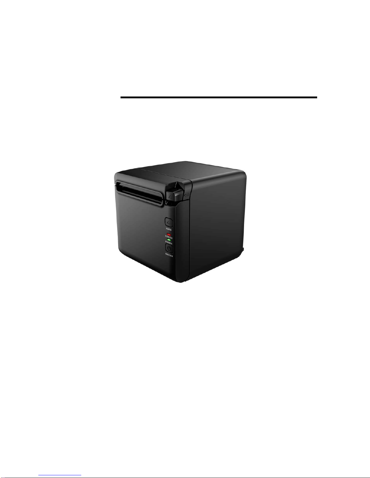
Partner RP-700 User manual

USER’S MANUAL
Thermal Receipt Printer
RP-700
Partner Tech Corporation

RP-700User’s Manual
Declaration
Information in this document cannot be changed without notice. Partner Tech Corporation
reserves the right to improve products as new technology, components, software, and firmware
become available. If users need further data about this product, please feel free to contact
Partner Tech Corporation or your local dealer.
No part of this document may be reproduced or transmitted in any form by any means,
electronic or mechanical, for any purpose without the express written permission of Partner
Tech Corporation.
Copyright
Copyright © 2017 by Partner Tech Corporation
Printed in China
Version 1.0
Trademark
Registered trademark of Partner Tech Corporation
Warning and Caution
Warning: Items shall be strictly followed to avoid injury or damage to body and devices.
Caution: Items with important information and prompts for operating the printer.
Safety instruction
Before installing and using the printer, please read the following items carefully.
1. Safety warning
Warning: Do not touch the cutter of the printer.
Warning: The print head is a thermal element and it is at a high temperature during printing
or just after operation, therefore do not touch it or its peripherals for reasons of
safety.
Warning:The print head is an ESD-sensitive device. To avoid damage, do not touch either
its printing parts or connecting parts.
- 1 -

RP-700User’s Manual
2. Caution
1) Install the printer on a flat and stable place.
2) Reserve adequate space around the printer so that convenient operation and maintenance
can be performed.
3) Keep the printer away from water source, and avoid direct exposure to sun light, strong light
and heat of fire.
4) Do not use or store the printer in a place exposed to high temperature, moisture and serious
pollution.
5) Do not place the printer on a place exposed to vibration or impact.
6) No dew condensation is allowed to the printer. In case of such condensation, do not turn on
the power until it has completely evaporated.
7) Connect the DC adapter to an appropriate grounding outlet. Avoid sharing a single
electrical with large power motors and other devices that may cause the fluctuation in
voltage.
8) Disconnect the DC adapter when the printer is not used for a long time.
9) Do not let the water or electric materials (like metal) go into the printer. If this happens, turn
off the power immediately.
10) Do not allow the printer to start printing when there is no recording paper installed;
otherwise the print head and platen roller will be seriously damaged.
11) To ensure the print quality and normal lifetime, use recommended or good quality paper.
12) Shut down the printer when connecting or disconnecting interfaces connectors to avoid
damage to the control board.
13) Set the print darkness to a lower grade as long as the print quality is acceptable. This will
help to keep the print head durable.
14) The printer should only be disassembled or repaired by a technician, who is certified by the
manufacturer.
15) Keep this manual safe and at hand for ready reference.
Caution: The following content about cutter only applies to printers with cutter.
- 2 -

RP-700User’s Manual
Contents
1INTRODUCTION.....................................................................................................................................- 1 -
1.1 OUTLINE ............................................................................................................................................- 1-
1.2 FE AT UR ES ...........................................................................................................................................- 1-
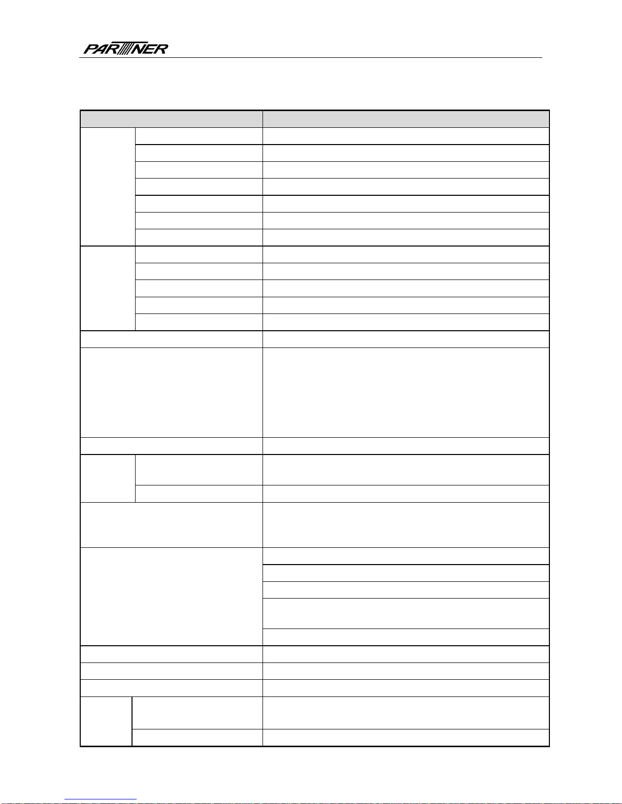
2SPECIFICATION.....................................................................................................................................- 2 -
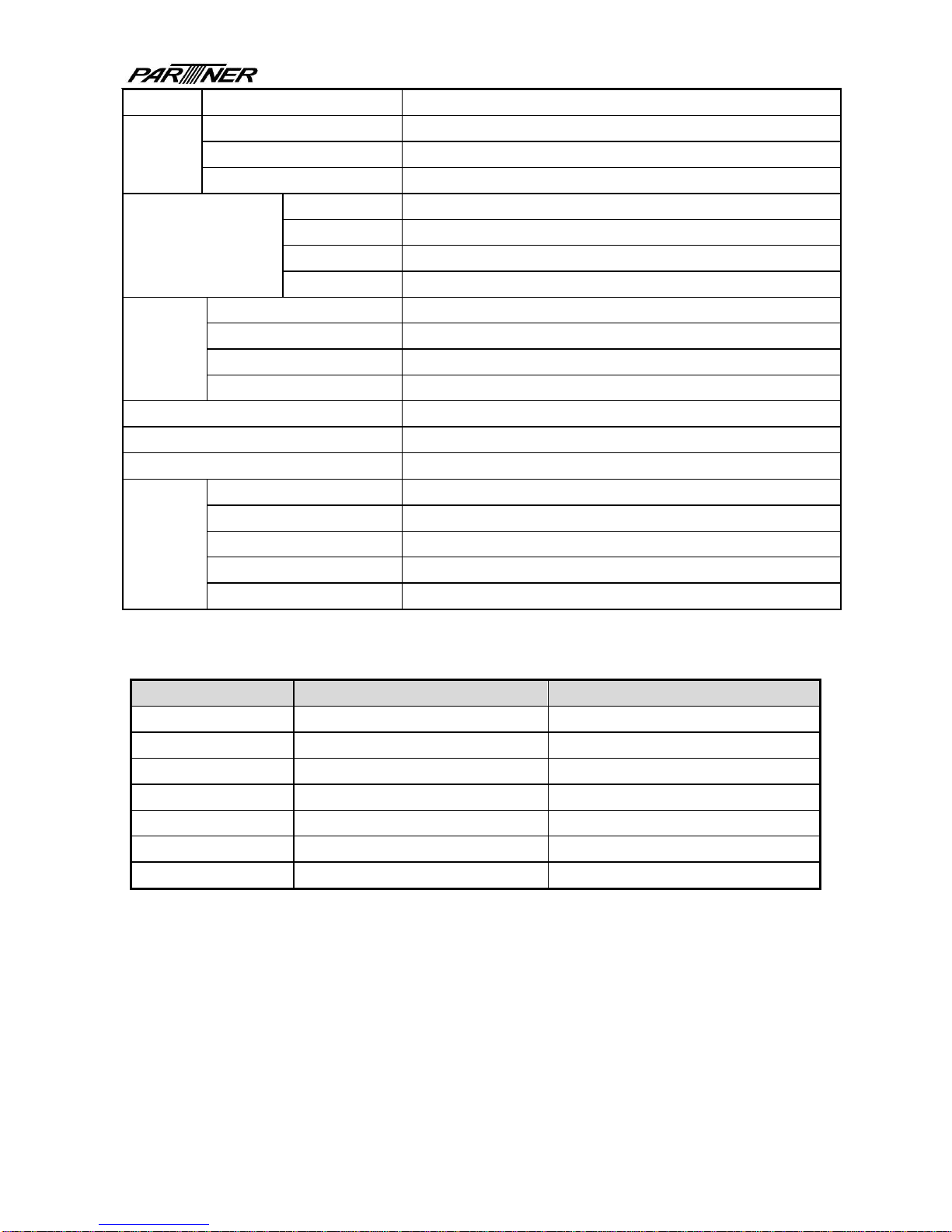
2.1 TECHNICAL SPECIFICATION .................................................................................................................- 2-
2.2 CUTTER PARAMETERS .........................................................................................................................- 3-
2.3 PAPER SPECIFICATION .........................................................................................................................- 3-
2.3.1 Parameters of continuous paper...............................................................................................- 3 -
2.3.2 Parameters of marked paper.....................................................................................................- 4 -
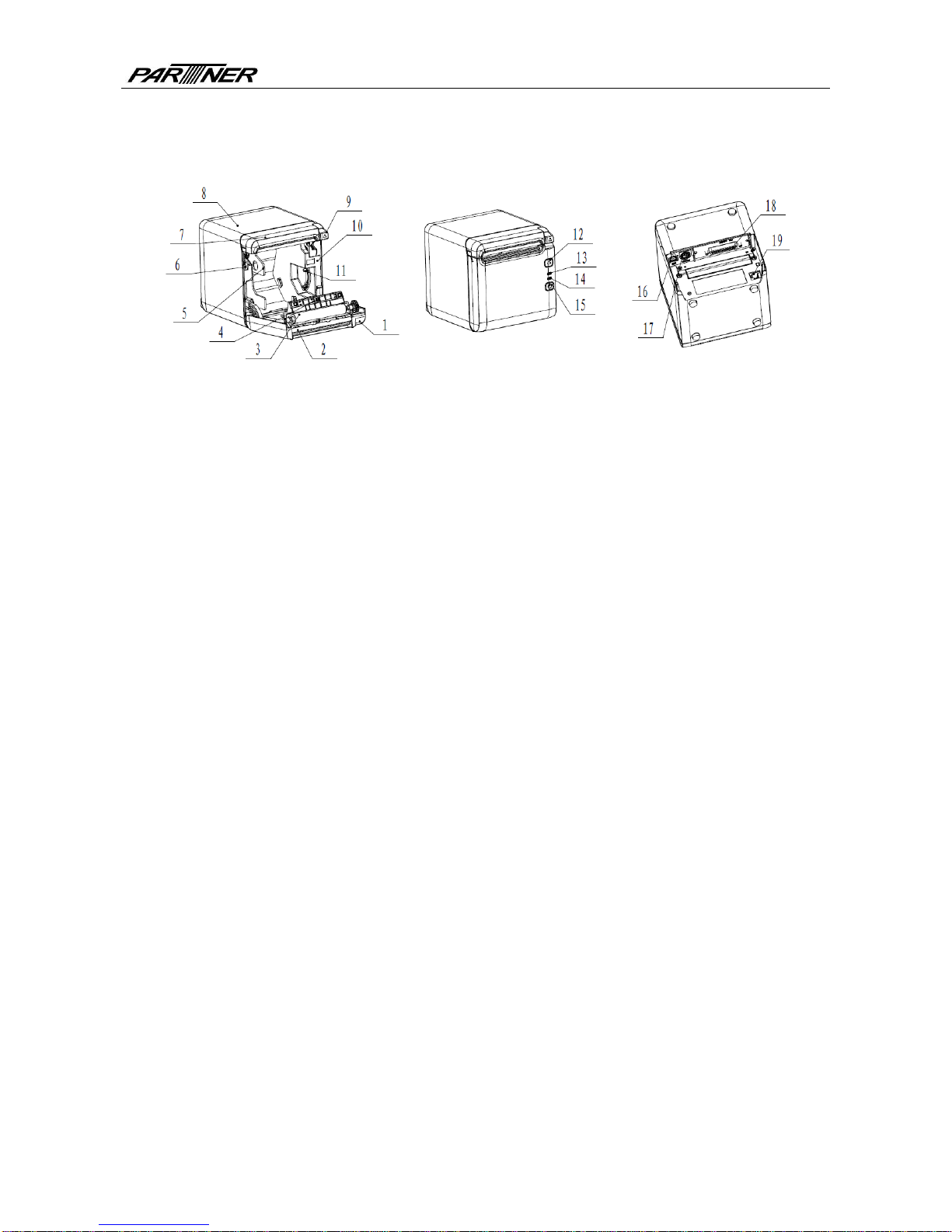
3APPEARANCE AND COMPONENTS...................................................................................................- 5 -
3.1 APPEARANCE AND MODULES...............................................................................................................- 5-
3.2 LED AND BUZZER ...............................................................................................................................- 7-
4INSTALLATION.......................................................................................................................................- 8 -
4.1 UNPACKING ........................................................................................................................................- 8-
4.2 PRINTER INSTALLATION ......................................................................................................................- 8-
4.3 POWER AND COMMUNICATION INTERFACE............................................................................................- 9-
4.3.1 Power connection.......................................................................................................................- 9 -
4.3.2 Interface connection...................................................................................................................- 9 -
4.3.3 USB interface connection........................................................................................................- 10 -
4.3.4 Cash drawer connection..........................................................................................................- 10 -
4.4 PAPER ROLL INSTALLATION ...............................................................................................................- 10 -
4.4.1 Paper type confirmation...........................................................................................................- 10 -
4.4.2 Install/replace paper roll..........................................................................................................- 10 -
4.5 PAPER NEAR END POSITION ADJUSTMENT ...........................................................................................- 12 -
4.6 POWER-ON AND SELF-TEST................................................................................................................- 13 -
4.6.1 Power-on...................................................................................................................................- 13 -
4.6.2 Print self-test page...................................................................................................................- 13 -
4.7 HEXADECIMAL DUMPING FUNCTION ..................................................................................................- 13 -
5ROUTINE MAINTENANCE ..................................................................................................................- 15 -
- 3 -

RP-700User’s Manual
5.1CLEANING THE PRINT HEAD AND THE PLATEN ROLLER........................................................................- 15 -
5.2 CLEANING THE MARK SENSOR...........................................................................................................- 15 -
5.3 CLEARING THE JAMMED PAPER AND THE CUTTER ERROR ....................................................................- 15 -
6INTERFACE SIGNAL...........................................................................................................................- 16 -
6.1 SERIAL INTERFACE............................................................................................................................- 16 -
6.2 MFI (BT) INTERFACE........................................................................................................................- 16 -
6.3 USB INTERFACE ...............................................................................................................................- 17 -
6.4 ETHERNET INTERFACE.......................................................................................................................- 17 -
6.5 DOUBLE COMMUNICATION INTERFACE...............................................................................................- 18 -
6.6 POWER INTERFACE DEFINITION..........................................................................................................- 19 -
6.7 CASH DRAWER INTERFACE SIGNAL DEFINITION ..................................................................................- 19 -
7TROUBLESHOOTING..........................................................................................................................- 21 -
7.1 PRINTER DOESN’T WORK...................................................................................................................- 21 -
7.2 ERROR LED AND BUZZER ALARM......................................................................................................- 21 -
7.3 PROBLEMS DURING PRINTING ............................................................................................................- 21 -
8POWER MANAGEMENT .....................................................................................................................- 22 -
9DUMP MODE ........................................................................................................................................- 23 -
APPENDIX BUTTON CONFIGURATION ................................................................................................- 24 -
- 4 -

RP-700User’s Manual
1 Introduction
1.1 Outline
RP-700 is developed for high-end thermal receipt printing market, which is widely used.RP-700
can be connected with other devices via serial, USB, MFi(BT) andEthernet. It provides drivers
for operation systems such as Windows 2000 / XP /Server 2003 / Vista / Server2008 / Win7 /
Win8 /Win8.1 / Win10/Server 2012, POSReady2009 / POSReady7, Linux, Mac and
OPOS/JavaPOS/Android/iOS middleware.
Note: Windows and Linux drivers support 64-bit operation system.
1.2 Features
Low noise, high printing speed;
Support continuous paper, marked paper;
Support paper saving, water mark, upside-down, two-color printing, etc.;
Compact size, can output paper from the front or the top according to users’ different
demands;
Rich interfaces:USB (fix on board), expandable serial / Ethernet / MFi(BT) interface;
- 1 -

RP-700User’s Manual
2 Specification
2.1 Technical specification
Item Parameter
Printing
Print method Direct thermal line printing
Resolution 203 × 203DPI; 203 × 180DPI
Paper width 57.5/80/82.5mm
Print width Max.80mm
Print speed Max.250mm/s
Flash LOGO Max. 1M bytes
Command buffer area 64K bytes, 4K bytes or 45 bytes
Interface
USB USB2.0 (full speed)
Serial interface RS-232C
MFi(BT) interface V4.0
Ethernet interface 10/100BASE-T
Cash drawer Can select to controlling 1~2 cash drawers
Memory RAM: 2MB, Flash: 4MB
Printer status detection
Paper end sensor/ black mark sensor;
Paper near end sensor;
Cover position sensor;
Paper presence sensor
Print head temperature sensor;
Printer voltage detection
Cut mode Full cut, partial cut
Barcode 1D UPC-A, UPC-E, CODE 39, CODE 93, CODE 128, EAN8, EAN13,
ITF, CODABAR
2D PDF417, QR, Maxicode
Fonts
Font A: 12 × 24
Font B: 9 × 17
Kanji font A: 24 × 24
Character set
95 Alphanumeric
14 types of international characters
128 x 68 code page
Optional: Traditional Chinese, Simplified Chinese
(GB2312/18030), Japanese, Korean, English, HK
User-defined font (95) & code page
Character enlargement All characters can be enlarged 1-6 times horizontally and vertically
Character rotation Rotation printing in four directions (0°, 90°, 180°, 270°)
Command ESC/POS compatible
Paper Paper type Thermal continuous paper
Thermal marked paper
Paper roll OD Max. 83mm
- 2 -

RP-700User’s Manual
Paper thickness 0.06mm~0.10mm thermal paper
Power
supply
Input 100-240VAC, 50-60Hz
Output 24V ± 5% DC, average current 2A
External or not External power adapter
Human-machine
interface
Power switch Support
Button Support
LED Support, including POWER LED and ERROR LED
Buzzer Support, 24V buzzer
Reliability
Lifetime of print head ≥150Km (standard test sample with 12.5% duty ratio)
Lifetime of cutter 2,000,000 cuts (standard test condition)
MCBF 70,000,000 lines
MTBF 360,000 hours (main control board)
Operation temperature and humidity 5°C~45°C,20%~90%RH(40°C)
Storage temperature and humidity -40°C~60°C,10%~90%RH(40°C)
Overall dimensions 127mm(L)*127mm(W)*134mm(H)
Functions
Saving paper Support
Button configuration Support (configure the printer without computer)
Right-up-side printing Support
Water mark printing Support
Gray scale printing Support
Table 2.1-1 Technical specifications
2.2 Cutter parameters
Item Parameter Remarks
Cutting method Sliding blade
Cutting time
500ms The time of one cut
Cutting interval 3s 20 cuts/minute (Max.)
Applicable paper types 0.06mm~0.10mm thermal paper
Operation voltage 24VDC
Max. operation current 1.2A Operation voltage 24VDC
Cutter lifetime 2,000,000 cuts Standard test condition
Table 2.2-1 Technical parameters of cutter
2.3 Paper specification
2.3.1 Parameters of continuous paper
Paper type: thermal paper
Paper supply mode: paper roll
Paper width: 57.5/80/82.5mm
Paper thickness: 0.06mm-0.10mm
Thermal layer: outward
- 3 -

RP-700User’s Manual
Paper roll specification: paper roll OD Max ф83 mm, core ID Min. ф12.8mm
Paper recommended:
Paper model Manufacturer
600-3.1 APPLETON Papers Inc
KLS_46_e KANZAN Spezialpapiere GmbH
FD210 OJI Paper CO., LTD.
Table 2.3-1 Recommended thermal paper model
2.3.2 Parameters of marked paper
RP-700 can support marked paper printingand set the cutting and initial printing position
accurately. The marked paper not only should meet the specifications of thermal paper roll, but
also should meet the following requirements:
L1 mark height: 3mm≤ L1≤13mm
L2 mark length: L2≥8mm
L3 distance between two marks: 30mm≤L3<450mm
Thermal side mark sensor position: reserved the left/middle/right positions
Non-thermal side mark sensor position: the middle/left/right positionis selectable
Reflectivity: The reflectivity of the black mark must be no more than 15% while the reflectivity
of the paper itself should exceed 85%. There should be no image between the two marks,
such as the advertisement, etc.
Caution:
Please use the recommended paper or its equivalents. Using the paper of low quality might
affect the print quality and shorten the lifetime of print head;
Do not stick paper onto the core shaft;
If the paper is contaminated by chemical or oil, it may discolor or lose heat sensitivity at the
polluted spot, which will affect the print affect;
Do not rub the paper surface with hard objects, otherwise it may affect the print affect;
When the environment temperature goes up to 70℃, paper will discolor. Thus don not use or
store paper under high temperature, high humidity and strong light conditions.
The mark is measured during printing and paper feeding. If the mark height value detected
by the sensor is bigger than thedefault value (default setting is 13mm), the printer will alarm
paper end.
- 4 -

RP-700User’s Manual
3 Appearance and components
3.1 Appearance and modules
Fig. 3.1-1 Schematic drawing of appearance and modules
1—To p cover 2—Cutter 3—Platen roller
4—Paper end sensor 5—Paper guide 6—Micro switch
7—Cutter cover 8—Middle cover 9—Cover open spanner
10—Paper cabinet 11—Paper near end sensor 12—FEED button
13—ERROR LED 14—POWER LED 15—POWER button
16—USB 17—Power interface 18—Communication interface
19—Cash drawer interface
Button and component function:
a FEED button (12)
Feed paper:
Printer will feed paper when the feed button is pressed down under normal condition. To
feed paper continuously, keep pressing the button.
Print configuration sample:
Pressing down the feed button while turning on the power, the printer will print out the
configuration sample, which includes print width, print speed, etc.
Enter button configuration mode:
Press down the feed button while turning on the power, the printer will print out the
configuration sample, andenter pause status (error LED flashes) after cutting paper. Keep
pressing the feed button at this time, the printer will enter button configuration mode.
Press the button to clear the cutter error:
Press the button for a short time when a cutter error occurs, the printer will try to clear the
cutter error automatically.
b Error LED (13)
Indicate printer status. Under normal status, the error LED is off. Under error status (e.g.
paper end, etc.), the error LED flashes.
c Power LED (14)
Indicate printer power status (ON/OFF).
d Power button (15)
- 5 -

RP-700User’s Manual
Press the button to connect power; press the button for a long time to disconnect the power.
e Top cover status detection sensor (14)
Detect the printercover status (open/closed).
f Paper presence sensor (12)
Detect the paper presence / absence status when continuous paper is used; detect the
paper marks when marked paper is used.
g Spanner for adjusting paper near end sensor(7)
Detect the paper roll status. Fast flashing of error LED indicates that the paper will be used
out soon and the user should replace the paper roll in time. Printer will work normally until
paper is used out.
h Paper guide (5)
Adjust the position of paper guide in the cabinet to adapt to different paper widths between
58/80mm. When the paper guide is removed, the printer can adapt to 82.5mm paper width.
- 6 -

RP-700User’s Manual
3.2 LED and buzzer
1) Functions of LED
LED name Status Description
Power LED
(green)
Always on Printer power is on.
Off Printer power is off.
Error LED
(red)
Off Printer is in normal status.
Flash Printer is in error status or paper near end status.
Buzzer Beep Printer is in error status.
Table 3.2-1 Functions of LED
2) Error type indicated by LED & buzzer
Error Type Error LED Buzzer
Print head is overheating Cycle flash 6 times Cycle beep 6 times
Printer voltage is abnormal Cycle flash 5 times Cycle beep 5 times
Cutter error Cycle flash 4 times
Cycle beep 4 times
Print head lift-up Cycle flash 3 times Cycle beep 3 times
Paper end Cycle flash 2 times Cycle beep 2 times
Paper near end Cycle flash slowly No beep
Cannot find mark or mark calibration error Cycle flash slowly No beep
Table 3.2-2 LED and indication information
Caution:
The temperature of the print head is detected by a thermal resistor. If the print head is
overheating, the protective circuit will shut off the power automatically and force the printer
to stop printing; the temperature of print head when printing is stopped is 65℃.
- 7 -

RP-700User’s Manual
4 Installation
4.1 Unpacking
Check whether all items, which are listed on the packing list, are present and in a good
condition. If any item is damaged or missing, please contact your dealer or the manufacturer.
4.2 Printer installation
1) RP-700 supports two working methods: out put the paper from the front or the top when
place the printer horizontally on the table. When the printer is placed horizontally on the
table, the incline installation angle should not exceed 5°, otherwise the paper near end
sensor will not work normally.
Fig. 4.2-1 Horizontally on the table (paper output from the front)
Fig. 4.2-2Horizontally on the table (paper output from the top)
2) Keep the printer far away from water source;
3) Do not place the printer in the place exposed to vibration and impact;
4) The printer power must be safely grounded;
5) It is recommended to keep proper space in order to guarantee the reliability and
operational convenience of the printer during operation and maintenance.
- 8 -

RP-700User’s Manual
Fig.4.2-3Printer maintenance and operation space
4.3 Power and communication interface
4.3.1 Power connection
1) Ensure that the power switch is turned off;
2) Insert the powerplug into the corresponding socket on the back of the printer.
Caution:
When the printer is not in use for a long period of time, disconnect the power cord from the
printer.
4.3.2 Interface connection
1) Ensure that the power switch is turned off;
2) Plug the connector into corresponding port and fix it with screw or spring as shown in the
figure;
3) Connect the other end of cable to the host.
- 9 -

RP-700User’s Manual
4.3.3 USB interface connection
1) Ensure that the power switch is turned off;
2) Plug the USB cable into corresponding interface in place as shown in the figure;
3) Connect the other end of USB cable to the host.
4.3.4 Cash drawer connection
1) Ensure that the power switch is turned off;
2) Plug the cash drawer cable into the cash drawer interface which locates at the back of
printer.
Caution:
The cash drawer interface is used to connect the cash drawer only (cannot connect with
phone wire, etc.).
4.4 Paper roll installation
4.4.1 Paper type confirmation
After connecting the power cord and interface cable, confirm paper type after media installation
before printing.
4.4.2 Install/replace paper roll
1) Turn off the printer;
2) Push the spanner in the direction shown in the Fig. to open the top cover;
3) Place the paper roll into the printer;
4) Close the top cover.
Fig. 4.4-1 Schematic drawing of paper roll installation/replacement
- 10 -

RP-700User’s Manual
Fig. 4.4-2 Schematic drawing of paper roll installation/replacement
Caution:
Adjust the paper guide according to the paper specification: install the paper guide at the
position of 57.5 for 57.5 wide paper roll; install the paper guide at the position of 80 for 80
wide paper roll; and remove the paper guide for 82.5 wide paper roll. Pay attention that the
winding direction of paper roll should meet printer requirements. Remove the end in
operation hole firstly when disassemble the paper guides, and install the end in operation
hole firstly when install the paper guides;
Ensure that the paper roll is tightly wound; otherwise paper jam or other failure may occur;
Paper roll should be placed stably in the paper cabinet without incline, or the printing willbe
affected.
Fig.4.4-3 Position of 57.5Fig. 4.4-4 Position of 80
Fig. 4.4-5 Operation hole
8
- 11 -

RP-700User’s Manual
4.5 Paper near end position adjustment
Fig. 4.5-1 Schematic drawing of paper near end position adjustment (output paper from the top)
Fig. 4.5-2 Schematic drawing of paper near end position adjustment (output paper from the front)
- 12 -

RP-700User’s Manual
The following diameter of core shaft of paper roll supported by the printer are as following: OD
of 16.2mm for plastic core shaft, OD of 20.8mm for paper type core shaft; adjust the paper near
end sensor to adjust the application method and paper near end alarm function for core shaft
with different outer diameters. There are four positions indicated by the scale marks for paper
near end alarm, and users can rotate the paper near end adjustment spanner to make the
indication line locate at different position, which change the paper near end alarm functions
under different application conditions. The position 1 and 2 are for the application that output
paper from the top, position 1 is for plastic core shaft of paper roll and position 2 is for paper
type core shaft of paper roll. The position 3 and 4 are for the application that output paper from
the front, position 3 is for paper type core shaft of paper roll and position 4 is for plastic core
shaft of paper roll.
4.6 Power-on and self-test
4.6.1 Power-on
1) Ensure that the printer is connected to power;
2) Turn on the power switch to power on the printer.
4.6.2 Print self-test page
1) Ensure that the printer is connected to power, and that paper roll is installed;
2) Ensure that the power LED is off and the printer is under power-off condition.
3) Press the feed button while turning on the printer power, and then release the button. The
printer will print out configuration information and prompt characters “Press and Release
FEED key to print characters” and “Press and Hold FEED key to config the printer”. Then
the printer enters pause status, and the error LED flashes;
4) Pressing the feed button momentarily, the printer will print out a character test sample, and
the printing of self-test page is completed. Pressing the feed button for a long time, the
printer will enter button configuration mode.
4.7 Hexadecimal dumping function
After entering Hexadecimal dumping mode, the printer will print out the data transmitted from
the host computer in hexadecimal and their corresponding ASCII characters.
The sample printed under Hexadecimal dumping mode is as follows:
Fig. 4.7-1 Print sample under Hexadecimal dumping mode
- 13 -

RP-700User’s Manual
Using Hexadecimal dumping mode:
1) Entering Hexadecimal dumping mode in the following ways:
a. Open the printer mechanism and turn on the printer while pressing the feed button.
Release the button after the printer alarms (LED flashes and buzzer beeps).
b. Send command “GS ( A”.
2) The printer first prints "Hexadecimal Dump To terminate …..", and then prints the data
transmitted from the host in hexadecimal and their corresponding ASCII characters.
3) Exiting from Hexadecimal dumping mode in the following ways:
a. Turn off the power, and then restart the printer.
b. Press the feed button three times.
Caution:
If the hexadecimal data has no corresponding ASCII characters, the printer will print ".";
Under Hexadecimal dumping mode, only commands DLE EOT, DLE ENQ, or DLE DC4 are
valid.
The data of the last character line can be printed by pressing down the feed button.
8
- 14 -

RP-700User’s Manual
5 Routine maintenance
Caution:
Before starting routine maintenance, ensure that the printer power is turned off.
Do not use organic solvents like gasoline or acetone.
When cleaning sensors, do not turn on the printer power until the pure alcohol has
completely evaporated.
It is recommended that the maintenance cycle should not be longer than one month.
5.1 Cleaning the print head and the platen roller
Follow the steps below to clean the print head and the platen roller:
1) Turn off the printer and open the top cover;
2) If the printing was just finished, please wait for the print head to cool down completely;
3) Wipe off the dust and stains on the surface of print head and platen roller with alcohol cotton
(it should be wrung out);
4) After the alcohol is completely evaporated, close the top cover.
5.2 Cleaning the mark sensor
When the printer cannot identify the mark effectively, the mark sensor should be cleaned.
The cleaning steps are as follows:
1) Turn off the printer;
2) Press the cover open lever to open the top cover;
3) Wipe off the dust and stains on the surface of the sensor with soft cotton cloth dipped with
pure alcohol (it should be wrung out);
4) Install the sensor cover after the pure alcohol is completely evaporated, then close the top
cover and finish mark sensor cleaning.
5.3 Clearing the jammed paper and the cutter error
Steps for clearing jammed paper and cutter error are as follows:
Method 1:
1) Turn off the printer power and turn the spanner to open the top cover;
2) Clear the jammed paper, and then close the top cover;
3) Turn on the printer power again, and then the cutter can be reset automatically.
Method 2:
1) Turn off the printer power, disassemble the cutter cover in the direction shown in the figure,
and turn the spanner to open the top cover;;
2) Clear the jammed paper, close the paper cabinet and turn on the printer power again, and
then the cutter can be reset automatically.
3) Install the cutter cover.
- 15 -
Table of contents
Other Partner Printer manuals

Partner
Partner MP-300 User manual

Partner
Partner RP-320 User manual

Partner
Partner RP-300-H User manual

Partner
Partner RP-100-300II User manual

Partner
Partner RP-300-H User manual

Partner
Partner RP-300 User manual

Partner
Partner LP-9300 User manual

Partner
Partner RP-330 User manual

Partner
Partner LP-2120 User manual

Partner
Partner LP-13150 User manual