PASCO ME-6978 User manual

Stroboscope (ME-6978)
Included PASCO Equipment
Strobe Control Box
Strobe Lamp (ME-6982)
AC to 15VDC 6.4A Power Adapter (not shown)
Power Cord (not shown)
Compatible PASCO Equipment
•Strobe Lamp (ME-6982)
•Photogate Head (ME-9498A)
Introduction
When used with a ME-6982 Strobe Lamp (included), the PASCO
ME-6978 Stroboscope produces intense, short-duration flashes
of white light suitable for strobe photography, and for "stopping
the motion" during laboratory experiments. The flash rate is
adjustable from 1 to 500 flashes per second (1 to 500 Hz or 60
to 30,000 RPM), and the flash brightness is adjustable from 1
(dimmest) to 25 (brightest).
The Strobe Control Box can control up to four Strobe Lamps at
one time. The Strobe Control Box can also be used to trigger a
second Stroboscope, or it can be triggered by an external device
such as a PASCO Photogate Head. The ability of the
Stroboscope to respond to a trigger from an external device
allows strobe flashes to be synchronized with an external event.
This can be used to ensure that a strobe photograph is taken at
a critical instant.
Basic Operation
The power supply comes with a power cord. Connect the power
adapter to the POWER port on the side of the Stroboscope.
Connect the power cord between the power adapter and an
appropriate electrical outlet. Connect the included Strobe Lamp
to one of the four Strobe Lamp ports on the top end of the
Strobe Control Box. Connect up to three additional Strobe
Lamps to the Strobe Lamp ports.
Slide the OFF/ON switch on the right side of the Strobe Control
Box to the ON position. The green light-emitting diode (LED)
next to HZ on the top panel will begin to slowly flash. The digital
display will show 10.0. The Stroboscope is active, but the
attached Strobe Lamp(s) will not flash yet.
POWER Port
OFF/ON Switch
Strobe Lamp ports
To make the Strobe Lamp start flashing, press the LAMP button
on the front panel. The green LED next to HZ on the front panel
will shine continuously, and the strobe lamp(s) will flash. Adjust
the flash rate with the COARSE and FINE knobs and adjust the
brightness with the BRIGHTNESS knob.
CAUTION: Do not look directly into the Strobe
Lamp when the LEDs are flashing!
To make the Strobe Lamp stop flashing, press the LAMP button
again. The green LED next to HZ on the front panel will slowly
flash.
Front Panel
The front panel has the Digital Display, FUNCTION LEDs,
FUNCTION button, LAMP button, COARSE and FINE control
knobs, and BRIGHTNESS knob.
Digital Display
FUNCTION LEDs: HZ, RPM, and TRIGGER
FUNCTION button
LAMP button
COARSE and FINE controls
BRIGHTNESS control
Product Guide | 012-10467C
1

FUNCTION Button and LEDs
The FUNCTION button cycles through three functions: HZ,
RPM, and TRIGGER. Each function is indicated by its respective
LED. The button cycles endlessly through the three functions.
Whenever you select a new function, a green LED flashes
slowly. This indicates that the function’s controls are active, but
the Strobe Lamp does not flash. You can change the flash rate
and brightness without actually flashing the lamp.
The HZ and RPM modes are identical except for the displayed
units. Note that the Stroboscope defaults to 10.0 Hz or 600
RPM when turned on. The maximum flash rate is 500 Hz or
30,000 RPM. The minimum flash rate is 1 Hz or 60 RPM.
The TRIGGER mode indicates that one of two things may
happen. The first is that the Strobe Lamp(s) will flash when the
Stroboscope receives a valid external signal, such as a pulse
from a Photogate Head connected to the IN port on the end of
the Stroboscope. The second is that an external Stroboscope
attached to the OUT port will be activated. When the
Stroboscope is in TRIGGER mode, the Digital Display shows the
amount of delay time between the valid external signal and the
lamp flash. The display ranges from 0 to 1000 milliseconds. The
default delay is 100 milliseconds (0.1 seconds).
LAMP Button
The LAMP button controls the Strobe Lamps attached to the
Stroboscope when the Stroboscope is in the HZ or RPM mode.
Press the LAMP button once to start the flashing. The HZ or
RPM LED will shine continuously.
Press the LAMP button again to stop the flashing. The
FUNCTION LED will return to a slow flashing mode. Note that
pressing the FUNCTION button when the lamp is flashing turns
off the lamp and also advances the function to the next
selection.
COARSE and FINE Control Knobs
The COARSE and FINE control knobs adjust the flash rate when
the Stroboscope is in HZ or RPM mode, and they adjust the
delay time between a valid external signal and the lamp flash
when the Stroboscope is in TRIGGER mode. Table 1 shows how
much a single slow 'click' of the COARSE or FINE control knobs
will change the displayed flash rate or delay time. Maximum and
minimum settings are also shown.
Table 1. COARSE and FINE
COARSE FINE Maximum Minimum
HZ 1.0 Hz 0.1 Hz 500.0 Hz 1.0 Hz
RPM 10 RPM 1 RPM 30,000 RPM 60 RPM
TRIGGER 10 ms 1 ms 1000 ms 0 ms
Each control knob incorporates a "speed-up" function that gives
the user the option of high resolution or rapid changes in the
Digits Display. As an example, the combination of
COARSE/FINE and speed-up means that the RPM display can
be changed anywhere from 1 RPM (FINE knob moved slowly)
up to 100 RPM (COARSE knob moved quickly) per "click" of the
control.
BRIGHTNESS Control Knob
The BRIGHTNESS Control Knob operates similarly to the flash
rate controls, except that it controls the brightness of the lamp
while flashing by setting the duration of each flash. The longer
the duration, the brighter the flash and vice versa. The control
operates using a relative scale of 1 to 25 in brightness for all
three functions (HZ, RPM, and TRIGGER), with "1" being the
dimmest and "25" being the brightest.
For TRIGGER mode with an external device connected to the
TRIGGER - IN port, the brightness control range of 1 to 25
arbitrarily maps to a lamp on-time range of 50 to 400
microseconds, since we don’t know the flash repetition rate. In
other words, when the brightness control is at "1", each
triggered flash of the strobe lamp lasts 50 microseconds, and
when the brightness control is at "25", each flash of the strobe
lamp lasts 400 microseconds.
Whenever the brightness control knob is moved while in HZ,
RPM, or TRIGGER mode, the seven-segment display will
automatically switch to display relative brightness. You can
easily differentiate this display from the other displays by
noticing that the brightness is left justified, while all the other
displays are right justified. Three seconds after the brightness
control knob becomes stationary, the display will revert to
displaying Hz or RPM.
SAVE and RECALL
SAVE: If the FUNCTION button is held down for more than one
second, all of the LEDs light up momentarily and the
Stroboscope saves almost all of the setup information to non-
volatile memory. This includes frequency in Hz, RPM, and
TRIGGER delay settings. The brightness setting is not saved.
Only one group of settings is saved, and any previously saved
setups are overwritten.
RECALL: If the LAMP button is held down for more than one
second, all of the LEDs light up momentarily, and the
Stroboscope recalls the setup information from memory. This
includes frequency in Hz, RPM, and TRIGGER delay settings.
The brightness setting is not recalled.
TRIGGER IN and TRIGGER OUT
TRIGGER - OUT
TRIGGER - IN
The TRIGGER - IN and TRIGGER - OUT ports at the end of the
Stroboscope will accept 1/4 inch diameter stereo phone plugs
(also known as "tip-ring-sleeve" plugs).
Stroboscope | ME-6978
2

TRIGGER mode is indicated only by the FUNCTION LED and is
designed primarily for use with PASCO Photogates. For
example, connect a PASCO Photogate to the TRIGGER - IN
port and set the Stroboscope to the TRIGGER mode with a
Strobe Lamp attached. Press the LAMP button. The lamp will
flash each time that the photogate’s infrared beam is interrupted.
The 7-segment display continuously displays the external trigger
(TRIGGER - IN) display setting. The setting defaults to zero, so
there is essentially no delay between the trigger being received
and the lamp turning on. The COARSE and FINE controls may
be used to adjust the trigger delay time from 0 to 1000, with
each increment equaling one millisecond. The BRIGHTNESS
control is also active and may be adjusted from a relative
brightness level of 1 to 25.
Multiple Stroboscopes
TRIGGER IN/OUT may also be used to connect multiple
Stroboscope units when used in HZ or RPM modes. Similar to
usage with a Photogate, each unit flashes along with the first or
"primary" unit. There are three special considerations when
using the Strobe with the primary unit in HZ or RPM.
First, configure the primary controller to operate in HZ or RPM.
Configure each secondary unit to operate in TRIGGER mode.
Connect the stereo patch cable from the primary controller’s
TRIGGER-OUT jack to the secondary unit’s TRIGGER-IN jack.
A large number of Strobes could be connected this way.
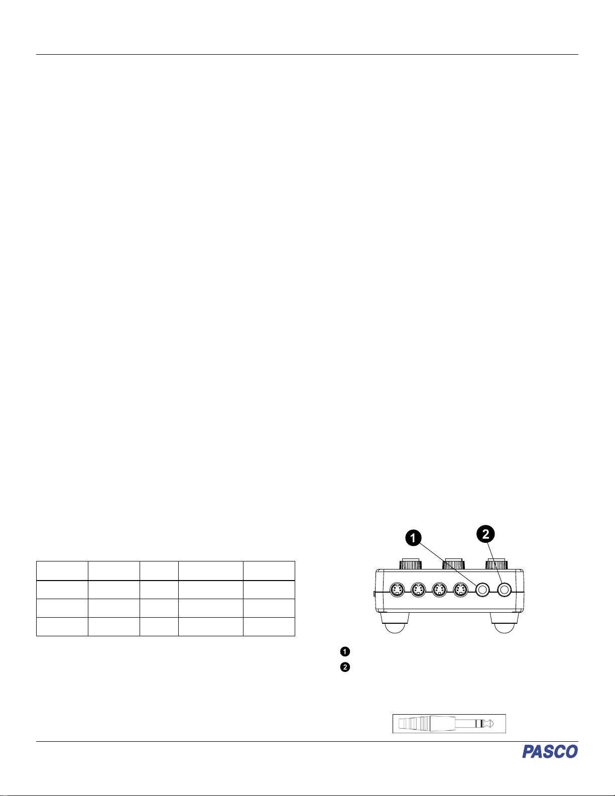
NOTE: A stereo phone plug-to-stereo phone plug
cable is needed to connect two Stroboscopes
together.
Second, to obtain consistent brightness from the secondary
lamps, the secondary unit(s) will usually need to have their
brightness control adjusted to where the actual levels match that
of the primary Strobe controller. When equal brightness is
attained, the brightness level as shown on each display may not
match. Matching the light levels is best done by eye, without
regard to the numerical brightness level displayed.
Lastly, if used, the trigger delay will have to be adjusted with
care. If the secondary unit(s) delay time is set longer than the
time between triggers from the primary controller, the secondary
unit lamps will stop flashing or flash at an incorrect rate.
Proper operation using an external trigger requires that the
trigger source be "debounced". Use of ordinary mechanical
switches without debouncing circuitry can lead to multiple
flashes, as well as flashes whenever the switch changes state.
The Stroboscope supplies a TTL level signal for the trigger
output (TRIGGER - OUT) and can supply 5 volts (50 mA
maximum) from the stereo plug "tip" to power external switches.
The TRIGGER - OUT is designed to be connected to the
TRIGGER - IN on a second Stroboscope. The advantage of
being able to connect two (or more) Stroboscopes together is
that the number of Strobe Lamps, and therefore the total
brightness of each flash, can be increased.
Specifications and Accessories
Visit the product page at pasco.com/product/ME-6978 to view
the specifications and explore accessories. You can also
download support documents from the product page.
Technical Support
Need more help? Our knowledgeable and friendly Technical
Support staff is ready to answer your questions or walk you
through any issues.
Chat pasco.com
Phone 1-800-772-8700 x1004 (USA)
+1 916 462 8384 (outside USA)
Email support@pasco.com
Limited Warranty
For a description of the product warranty, see the Warranty and Returns page at
www.pasco.com/legal.
Copyright
This document is copyrighted with all rights reserved. Permission is granted to non-
profit educational institutions for reproduction of any part of this manual, providing
the reproductions are used only in their laboratories and classrooms, and are not
sold for profit. Reproduction under any other circumstances, without the written
consent of PASCO scientific, is prohibited.
Trademarks
PASCO and PASCO scientific are trademarks or registered trademarks of PASCO
scientific, in the United States and in other countries. All other brands, products, or
service names are or may be trademarks or service marks of, and are used to
identify, products or services of, their respective owners. For more information visit
www.pasco.com/legal.
Product end-of-life disposal
This electronic product is subject to disposal and recycling regulations
that vary by country and region.
It is your responsibility to recycle your electronic equipment per your
local environmental laws and regulations to ensure that it will be
recycled in a manner that protects human health and the environment.
To find out where you can drop off your waste equipment for recycling,
please contact your local waste recycle or disposal service, or the place where you
purchased the product.
The European Union WEEE (Waste Electronic and Electrical Equipment) symbol
on the product or its packaging indicates that this product must not be disposed of
in a standard waste container.
CE statement
This device has been tested and found to comply with the essential requirements
and other relevant provisions of the applicable EU Directives.
FCC statement
This device complies with part 15 of the FCC Rules.
Operation is subject to the following two conditions:
(1) This device may not cause harmful interference, and (2) this device must accept
any interference received, including interference that may cause undesired
operation.
Product Guide | 012-10467C
3
Other PASCO Test Equipment manuals