PASCO ME-8236 User manual

Instruction Manual
012-13762C
Materials Testing Machine
ME-8236
Part of the
Materials Testing System
ME-8230
7100 N
Load Cell
Leadscrews
Calibration
Rod and Nut
Load Bar
(crosshead)
Tensile Samples*
(60)
Sensor
Cable
Load Bar
Round Nut
Velcro® Loop
Material
Safety Shield (2)
Velcro® Hook
Material
WARNING: Provide proper eye
protection when using the Materials
Testing Machine or its Accessories.
Operate the Materials Testing Machine
behind protective Safety Shields.
Crankshaft Base
USB Link*
*Items from the
ME-8230 Materials
Testing System
Materials Testing
Machine

Materials Testing Machine Introduction
2012-13762C
Materials Testing Machine (ME-8236)
.
*See the PASCO catalog or web site at
WWW.PASCO.COM
Materials Testing System (ME-8230)
.
Accessories and Other Items
.
.
*AP-8217A Replacement Test Coupons (Full Set) con-
sists of the AP-8222 Plastic Coupons and the AP-8223
Metal Coupons.
Introduction
The PASCO Materials Testing Machine is a device for mea-
suring force and displacement for various materials as the
materials are stretched, compressed, sheared, or bent. The
Materials Testing Machine has a built-in load cell (strain
gauge transducer) capable of measuring up to 7100 newtons
(N) of force (1600 pounds), and an optical encoder module
that measures displacement of the load bar. A crank-and-gear
system raises or lowers the load bar on two leadscrews (also
known as power screws or translation screws). Force data
from the load cell and displacement data from the encoder
module can be recorded, displayed, and analyzed by a
PASCO Interface with PASCO Data Acquisition Software.
The sensor cable from the Materials Testing Machine con-
nects to a PASPORT input port. (See the PASCO catalog or
web site at www.pasco.com for more information about
PASCO interfaces and data acquisition software.)
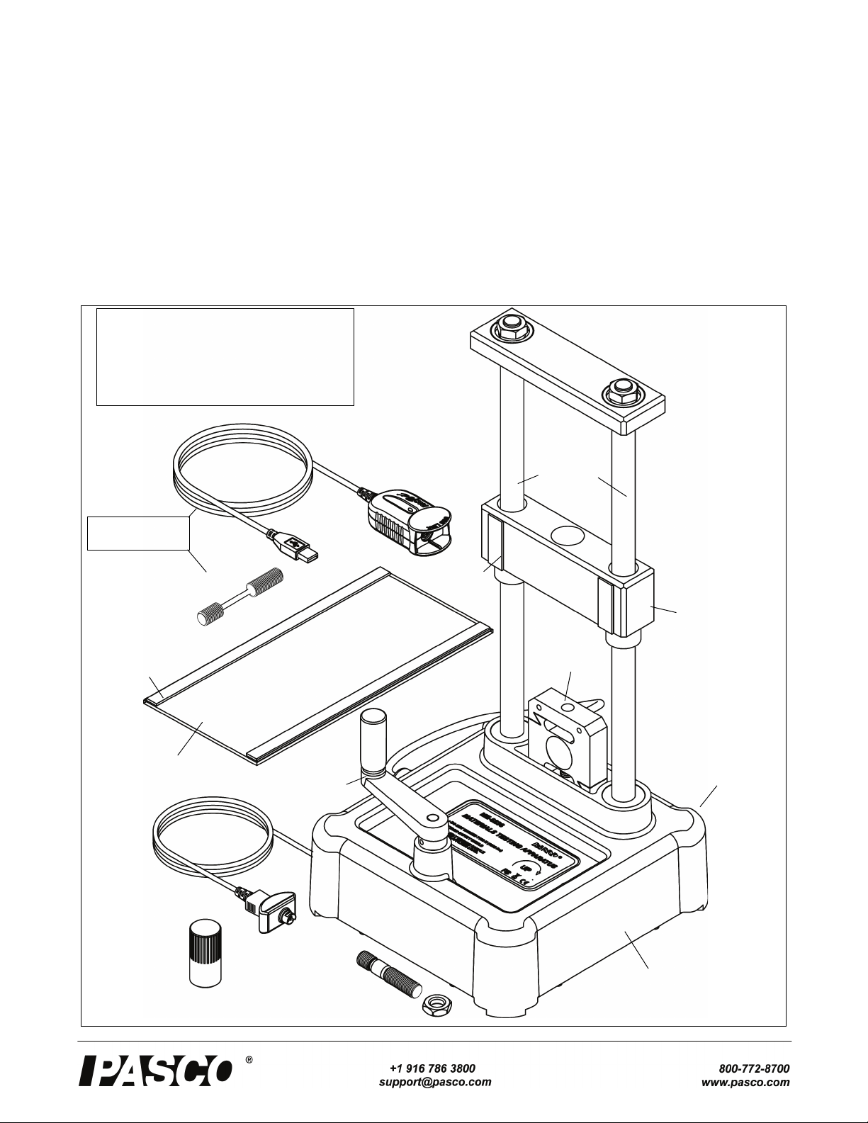
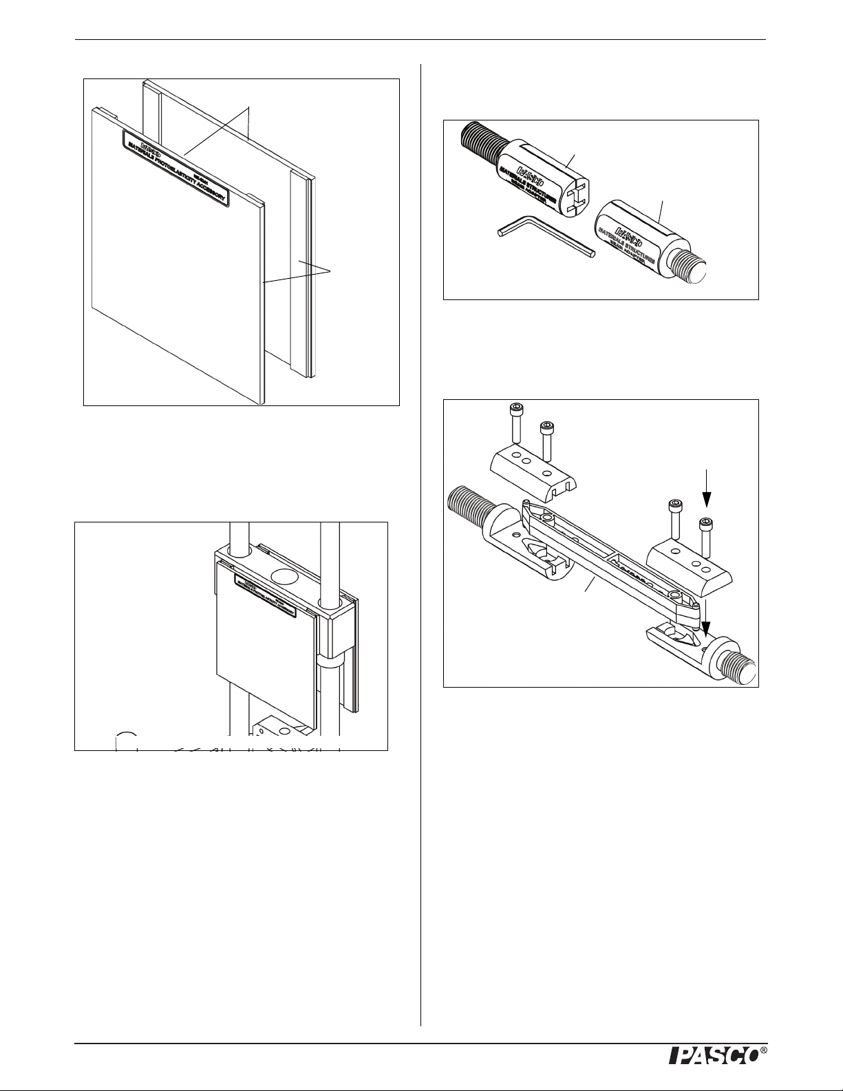
Included Equipment
The Materials Testing Machine includes a calibration rod
and nut, a load bar round nut, and a pair of safety shields
with Velcro® hook material.
Calibration Rod and Nut, Load Bar Round Nut,
Safety Shields
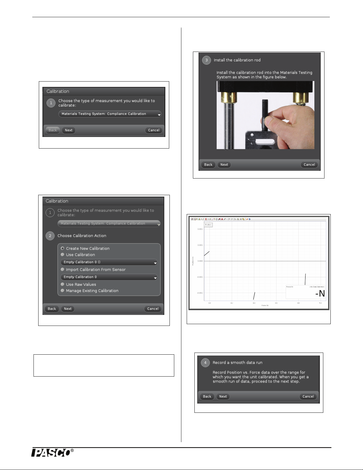
• The calibration rod and nut can be used to determine
how much the Machine itself flexes as force is applied,
either in tension or in compression.
• The load bar round nut is used to connect one end of a
tensile sample to the load bar, for example, or can be
used to attach an accessory or adapter to the load bar.
• The safety shields attach to the Velcro® loop material
on the front and back of the load bar.
Materials Testing System
The Materials Testing System (ME-8230) consists of the
Materials Testing Machine, plus a PASPORT interface called
the USB Link, PASCO Capstone Software, and sixty tensile
samples.
The USB Link connects the sensor cable of the Materials
Testing Machine to a USB port on a computer. The PASCO
Capstone software records, displays, and analyzes the data
from the Materials Testing Machine. The software is avail-
able as an automatic digital download from PASCO.
Included Items Included Items
Materials Testing Machine Calibration Rod and Nut
Load Bar Round Nut Safety Shield (2)
Required Items*
PASCO Interface (PASPORT compatible)
PASCO Capstone Data Acquisition Software
Model Materials Testing System Items
ME-8236 Materials Testing Machine
PS-2100A USB Link
UI-5401 PASCO Capstone Software
ME-8231 Tensile Sample, Aluminum (10)
ME-8232 Tensile Sample, Brass (10)
ME-8233 Tensile Sample, Annealed Steel (10)
ME-8234 Tensile Sample, Acrylic (10)
ME-8235 Tensile Sample, Polyethylene (10)
ME-8243 Tensile Sample, Steel (10)
Model Accessories
ME-8237 Materials Bending Accessory
ME-8238 Materials Coupon Adapter
ME-8239 Materials Shear Accessory
ME-8241 Materials Photoelasticity Accessory
ME-8242 Materials Structures Beam Adapter
ME-7011 Photoelastic I-Beams (24 each size)
Model Other Items
ME-8240 Materials Shear Samples (3 ea. of 3)
AP-8222* Coupons, Plastic (10 each of 4 types)
AP-8223* Coupons, Metal (10 each of 5 types)
Recommended Items
Structures Cast Beam Set (ME-7009)
Truss Set Members (ME-6993)

Model No.ME-8236 Operation
3
012-13762C
The tensile samples include four metals (2024-T3 aluminum,
360 brass, 1018 annealed steel, and 1018 steel) and two plas-
tics (acrylic and polyethylene) for tensile strength testing.
There are ten samples for each material.
Tensile Sample Information
All the tensile samples (ME-8231 through ME-8235 and
ME-8243) have an overall length of 90 millimeters (mm) or
3.5 inches. The center section of each sample has an approx-
imate diameter of 3.3 mm or 0.131 inches. The threaded
ends are metric M12 x 1.75.
The table shows typical values.
Accessories and Replacement Items
The accessories and adapters that are available separately for
the Material Testing Machine include the Materials Bending
Accessory (ME-8237), the Materials Coupon Adapter
(ME-8238), the Materials Shear Accessory (ME-8239), the
Materials Photoelasticity Accessory (ME-8241), the Materi-
als Structures Beam Adapter (ME-8242), and the Photoelas-
tic I-Beams (ME-7011). Other accessories and adapters are
being developed.
Also available are replacement items such as the previously
mentioned Tensile Samples, the Materials Shear Samples
(ME-8240) with nine metal rods (three each of aluminum,
brass, and steel), the Plastic Coupons (AP-8222) with ten
samples each of four different plastics, and the Metal Cou-
pons (AP-8223) with ten samples each of five different met-
als.
About This Manual
The manual describes the basic setup of the Materials Test-
ing Machine and the accessories and replacement items. It
also briefly describes the procedure for calibrating the Mate-
rials Testing Machine using the included calibration rod and
nut.
Experiment Guide
Operation
Caution: Be sure to wear adequate eye protection
when using the Materials Testing System or its
accessories. Operate the System from behind a
protective shield.
Basic operation involves mounting the Materials Testing
Machine firmly to a sturdy support, calibrating the Machine,
mounting the item to be tested onto the Materials Testing
Machine, connecting the Materials Testing Machine to an
interface for data recording, and then turning the crank to
apply tension (stretching), compression (squeezing), bend-
ing, or shearing (cutting) forces to the test item.
Secure the Materials Testing Machine
There are two holes through the base of the Materials Testing
Machine that can be used for bolting the Machine to a sturdy
support. The two 6 millimeter (mm) diameter holes are 15
centimeters apart; one on either side of the label.
Bolting the Machine will avoid the problem of the Machine
moving during a sample test. An option is to bolt the
Machine to a piece of wood or other material, and than use
large “C-clamps” to fasten the board to a table.
Calibration Setup
The calibration rod and nut can be used for calibrating the
Materials Testing Machine for compression or tension. The
PASCO Capstone data acquisition software includes a “wiz-
ard” that allows the calibration data for the Materials Testing
Machine to be stored for later use.
The reason for the calibration procedure using the calibration
rod and nut is that the calibration rod will not change shape
significantly under tension or compression. This means that
any displacement measured when the calibration rod is used
is due to the flexing of the Materials Testing Machine itself.
This “flexing” displacement can become part of the calibra-
tion information for the Machine that can be stored in the
Machine.
Table 1: Typical Values
Material Tensile
Strength
Young’s
Modulus
Aluminum 400 MPa 70 GPa
Brass 500 MPa 80 GPa
Steel 700 MPa 200 GPa
Annealed Steel 400 MPa 200 GPa
Polyethylene 30 MPa 1 GPa
Acrylic 80 MPa 3 GPa
diameter = 3.3 mm M12 x 1.75
19 mm
31.7 mm
NOTE: An Experiment Guide in electronic format
is available to download from www.pasco.com.
Enter “Materials Testing System” in the Search
window and look for the downloadable file(s)
under “Resources”.

Materials Testing Machine Operation
4012-13762C
Mount the Calibration Rod for Tension
To mount the calibration rod for tension, screw the
short-threaded end of the rod into the top of the load cell.
Lower the load bar until the threaded part at the top of the
calibration rod goes through the hole in the load bar. Screw
the load bar round nut onto the top of the calibration rod.
Mount the Calibration Rod for Compression
To mount the calibration rod for compression, screw the
short-threaded end of the rod into the top of the load cell.
Screw the calibration nut onto the top threaded part of the
calibration rod until the nut is at the bottom of the threaded
section. Lower the load bar until the bottom of the load bar
rests on the top of the calibration nut.
Attach the Safety Shields
Attach the Velcro® hook material on the two safety shields
to the Velcro® loop material on the front and back of the
Load Bar. Adjust the position of the shields so that they will
block any fragments that may come from the calibration rod
in case it accidentally breaks.
Prepare to Record Calibration Data
Connect the plug on the sensor cable into a PASPORT inter-
face, such as the USB Link. Connect the interface to a USB
port on a computer.
Start the PASCO Capstone software. Prepare to use the soft-
ware to calibrate the Material Testing Machine.
Optional: Change Sign
Note that the default for the Materials Testing Machine in the
software shows force and position as ‘negative’ when a ten-
sion force is applied.
• To change the sign for the force and position data, click
the “Hardware Setup” icon in the Tools palette.
• In the Hardware Setup window, click the “Properties”
icon (shaped like a gear wheel) to open the “Properties”
window for the Materials Testing System.
• In the “Properties” window, click the check box for
“Change Sign”. Click “OK” to close the “Properties”
window.
Load Bar
Round
Nut
Load Bar
(crosshead)
Calibration
Rod
Crank
Handle
Load
Cell
Figure: Mount Calibration Rod for Tension
Calibration
Nut
Figure: Mount Calibration Rod and Nut for Compression
Load
Cell
Load Bar
(crosshead)
Sensor
Cable Plug
PASPORT
Input Port
Figure: Click “Change Sign”

Model No.ME-8236 Operation
5
012-13762C
• Click the “Hardware Setup” icon to close the “Hardware
Setup” window.
Calibration
Step One
In the software, select the “Calibration” icon in the Tools
palette to open Step One of the “Calibration” window.
The default choice is “Materials Testing System: Compli-
ance Calibration”. Use this choice.
Step Two
• Click “Next” to show Step Two, the “Choose Calibra-
tion Action” menu.
The default choice is “Create New Calibration”. The other
choices are described in the appendix
.
Step Three
• Click “Next” to show the illustration in Step Three,
“Install the calibration rod”.
In addition to the illustration, a Graph display of Position
(m) versus Force (N) opens. A Digits display of Force (N) is
part of the Graph display
.
Step Four
• Click “Next” to open Step Four, “Record a smooth data
run”.
Figure: Step One, Calibration window
NOTE: Detailed information about the calibration
procedure is included in the Appendix.
Figure: Step Three, “Install the calibration rod”
Figure: Calibration Graph and Digits Displays
Position (m)
Force (N)
Digits display of
Force (N)
Figure: Step Four, Record a smooth data run
Figure: Step Two, Choose Calibration Action

Materials Testing Machine Operation
6012-13762C
“Seating” the Calibration Rod Before Recording
Calibration Data
See the Appendix at the end of the manual for information
on preparing the calibration rod.Click “Record” and collect a
smooth run of position versus force data. When the data col-
lection is finished, click “Stop”.
NOTE: A Polyno-
mial curve fit is auto-
matically applied to
the run of position
versus force data.
Step Five
• Click “Next” to open Step Five, “Polynomial Fit”.
NOTE: By default, the “Show Curve Fit Editor” window is
open in the “Polynomial Fit” window.
• If the message “Curve fit was successful” is shown,
click “Next” to open Step Six, “Name the calibration”.
NOTE: If the curve fit was not successful, use
“trial-and-change” in the Curve Fit Editor to adjust the coef-
ficients until the curve fit is successful. Click “Update Fit” to
determine if the new coefficients made a better curve fit
Step Six
.
• Type a name for the calibration in the text area. (Exam-
ple names might be “Calibration 7000” or “Tension Cal-
ibration”.)
Position versus
force data
Polynomial curve fit
Figure: Step Five, Polynomial Fit
Figure: Step Six, Name the calibration

Model No.ME-8236 Operation
7
012-13762C
Finishing Step
• Click “Finish” to store the calibration as part of the Cap-
stone file.
NOTE: The “Calibration” window goes back to Step One.
When you click “Next”, the “Choose Calibration Action”
window (Step Two) will show a menu of the stored calibra-
tion(s). Click “Use Calibration” to select a specific stored
calibration.
• Click the “Calibration” icon in the Tools palette to close
the “Calibration” window. Save the Capstone file for
future use.
Mount a Tensile Sample
Select a tensile sample to mount onto the Materials Testing
Machine. Put the end of the sample with the short threaded
section into the threaded hole in the top of the load cell.
Screw in the sample until the top edge of the short threaded
section is flush with the top of the load cell.
Lower the load bar so that the longer threaded section of the
sample goes up through the hole in the center of the load bar.
Adjust the load bar until the bottom edge of the longer
threaded section is flush with the bottom of the load bar.
While holding the tensile sample so it does not turn, screw
the sample nut onto the longer threaded section until the
sample is held tightly in place.
Attach the Safety Shields
Attach the Velcro® hook material on the two safety shields
to the Velcro® loop material on the front and back of the
Load Bar. Adjust the position of the shields so that they will
block any fragments that may come from the sample.
Record Data
Prepare PASCO Capstone software to record data. (If there is
a stored calibration file that is to be used, select it in the
“Calibration” window.)
Start data recording in the software. Turn the crank in a
clockwise direction to apply a tension force to the tensile
sample. Observe the graph display of force and position.
(Note that the default for the Materials Testing Machine in
the software shows force and position as ‘negative’ when a
tension force is applied.)
When the sample breaks, or is stretched the maximum
amount, stop data recording.
Materials Bending Accessory (ME-8237)
The Materials Bending Accessory includes a plunger, a
adjustable support anvils, and a small hex key (allen
wrench). The plunger is mounted on the bottom of the load
bar using the sample nut. The base for the adjustable anvils
is screwed onto the top of the load cell.
The spacing between the two triangular support anvils can be
adjusted. Use the hex key to loosen the screws holding the
anvils and slide them closer together or farther apart. Tighten
the screws securely.
Figure: Use Calibration
NOTE: Information about the calibration proce-
dure is included in the Appendix of this manual
and in the Experiment Guide that can be down-
loaded from the PASCO web page.
Load Bar
Sample
Nut
Tensile
Sample
Crank
Handle
Load
Cell
Figure: Mount Tensile Sample
Loop
Material
for Safety
Shield
Load Bar
(crosshead)

Materials Testing Machine Operation
8012-13762C
Use the sample nut to secure the plunger in place on the load
bar. Remove the screws from the base for the anvils and
align the base on top of the load cell. Use the screws and the
hex key to fasten the base in place.
Place a sample for testing on the two support anvils.
Attach the Safety Shields
Attach the Velcro® hook material on the two safety shields
to the Velcro® loop material on the front and back of the
Load Bar. Adjust the position of the shields so that they will
block any fragments that may come from the sample.
Apply a Force
Turn the crank counterclockwise to apply a compression
force through the plunger onto the sample. (Note that the
default in the software shows the force and position as ‘posi-
tive’ when a compression force is applied.)
Materials Coupon Adapter (ME-8238)
The Materials Coupon Adapter includes two coupon clamps,
a “tee-handle”, and a 3/8” socket (12 point). One clamp fits
in the load cell and the other fits in the load bar. They can be
used to mount a plastic coupon (AP-8222) or metal coupon
(AP-8223) onto the Materials Testing System for testing of
tensile strength.
Loosen but do not remove the hex nut on each clamp. The
jaws of the clamp are spring loaded, so the moveable jaw
will separate from the fixed jaw. Screw the clamp with the
shorter threaded section into the load cell. Put the threaded
section of the other clamp up through the hole in the load
bar, and use the sample nut to hold the upper clamp. NOTE:
Do not completely tighten the sample nut yet.
Carefully place one end of a coupon between the jaws of the
bottom clamp. While holding the moveable jaw to keep it
aligned with the fixed jaw, use the tee-handle and socket to
tighten the hex nut. CAUTION: Each coupon is fragile. Do
not let the moveable jaw twist out of alignment with the
fixed jaw as this might bend the coupon.
Turn the upper clamp so that it is aligned with the lower
clamp. Adjust the position of the load bar so that you have
room to carefully put the other end of the coupon between
the jaws of the upper clamp. Keep the movable jaw aligned
with the fixed jaw so that the coupon does not twist or bend.
Once again, tighten the hex nut.
Hold the upper clamp so it remains parallel to the lower
clamp and tighten the sample nut slightly to remove any
slack in the coupon.
Attach the Safety Shields
Attach the Velcro® hook material on the two safety shields
to the Velcro® loop material on the front and back of the
Load Bar. Adjust the position of the shields so that they will
block any fragments that may come from the sample.
Turn the crank clockwise to apply a tension force to the cou-
pon.
Figure: Materials Bending Accessory
Load
Cell
Plunger Sample
Anvil
Anvil
Crank
Handle
Sample
Nut
Base
Load Bar
(crosshead)
Movable
Jaw
Fixed
Jaw
Hex Nut
Upper
Clamp
Lower
Clamp
Metal
Coupon
Plastic
Coupon
Figure: Materials Coupon Adapter

Model No.ME-8236 Operation
9
012-13762C
Materials Shear Accessory (ME-8239)
The Materials Shear Accessory consists of two pieces of
hardened steel - a front piece and a back piece - held together
by a pair of permanent screws, and a package of Materials
Shear Samples. The front piece can slide vertically relative
to the back piece, which is designed to be mounted on the
load cell using an included hex key (allen wrench). The two
pieces have pairs of matching holes with four different diam-
eters to fit a variety of samples for testing. The hole diame-
ters are approximately 1/16”, 3/32”, 1/8”, and 5/32”. The
Materials Shear Samples includes three 1/8” diameter rods
each of three metals: aluminum, brass, and mild steel.
NOTE: Do not use a sample with a hardness greater
than mild steel.
Use the two mounting screws and the included hex key
(allen wrench) to attach the back piece of the Materials Shear
Accessory to the top of the load cell. Note that when the
front piece is raised by hand as far as it will go, the holes in
the front piece align with the matching holes in the back
piece.
Insert the test sample through the pair of holes that best
match the diameter of the sample. Use a sample that is long
enough so that it extends about 1/4” (6 mm) beyond the front
and back pieces. Doing this makes it easier to remove the
sample remnants from the accessory after the test.
Adjust the position of the load bar so that it rests on the top
surface of the front piece.
Attach the Safety Shields
Attach the Velcro® hook material on the two safety shields
to the Velcro® loop material on the front and back of the
Load Bar. Adjust the position of the shields so that they will
block any fragments that may come from the sample.
Turn the crank counterclockwise to apply a downward force
on the front piece of the accessory to shear the sample.
Materials Photoelasticity Accessory
(ME-8241)
Samples of clear plastic that are viewed through crossed
polarizers reveal patterns of different colors that show stress
distribution. The Materials Photoelasticity Accessory is
designed to work with the Materials Testing System to
demonstrate the photoelastic phenomenon in clear plastic
samples.
The Materials Photoelasticity Accessory consists of two
rectangles of polarizer material that can be attached to the
Velcro® loop material on the front and back of the Load Bar
of the Materials Testing System.
Front
Piece
Back
Piece
0.067”,
1.7 mm
0.099”,
2.5 mm
0.161”,
4.0 mm
0.130”,
3.3mm
Mounting
Screws
Materials Shear
Accessory
Figure: Materials Shear Accessory

Materials Testing Machine Operation
10 012-13762C
To place the polarizers on the Load Bar, align a polarizer
with the strips of loop material on the front of the Load Bar
and press the edges of the polarizer so that the hook material
adheres to the loop material. Repeat the process with the sec-
ond polarizer on the other side of the load bar.
Place a light source so that it shines through the polarizers
from behind.
Materials Structure Beam Adapter
(ME-8242)
The PASCO Structures System includes a variety of beams
that can be used with the Materials Testing System. The
beams are models of I-beams and other structure elements.
The Materials Structure Beam Adapter is designed to hold a
structures beam so that it can be tested under tension and
compression.
The Materials Structures Beam Adapter consists of two
clamps and an included hex key. Each clamp has two jaws,
one of which can be removed so that an end of a structures
beam can be put in the clamp. The threaded ends of the two
clamps fit in the load bar and load cell of the Materials Test-
ing System.
Use the included hex key to remove the screws that hold the
two parts of the clamp together. Put the ends of a structures
beam, such as a #3 I-Beam, into one part of each clamp, and
then use the screws to reattach the other part of each clamp.
Screw the clamp with the short threaded end into the top of
the load cell, and put the other clamp through the hole in the
load bar. Use the sample nut to secure the clamp to the load
bar.
Attach the Safety Shields
Attach the Velcro® hook material on the two safety shields
to the Velcro® loop material on the front and back of the
Load Bar. Adjust the position of the shields so that they will
block any fragments that may come from the sample.
Photoelastic I-Beams (ME-7011)
The Photoelastic I-Beams are similar to the #3 I-Beams and
#4 I-Beams that are part of the PASCO Structures Systems
(such as the Truss Set, ME-6990). However, the Photoelastic
I-Beams differ in that they are clear polycarbonate plastic
and do not have any holes in the web area of the beam. They
can be mounted on the Materials Testing System using the
Materials Structures Beam Adapter. When viewed with the
Polarizer
Hook
Material
Figure: Polarizers on Load Bar
Figure: Materials Structures Beam Adapter
Clamp for
Load Bar
Clamp for
Load Cell
Structures
Beam

Model No.ME-8236 Technical Support
11
012-13762C
Materials Photoelasticity Accessory, the distribution of stress
in the beams can be studied.
The set includes twenty-four each of the two sizes of
I-beams. The #3 I-Beam is 11.5 cm long, and the #4 I-Beam
is 17 cm long.
Maintenance
Regular maintenance for this equipment is minimal. The
leadscrews need to be kept clean, and they may need to be
re-lubricated at some point. Use a food grade anti-seize
grease containing PTFE (polytetrafluoroethylene, commonly
known as Teflon®).
If problems arise with the Materials Testing Machine, notify
PASCO scientific. It is not recommended that you attempt to
fix this equipment yourself. (See the Technical Support
information at the end of this manual.)
Specifications
Experiment Guide
NOTE: An Experiment Guide in electronic format is avail-
able to download from www.pasco.com. The Experiment
Guide includes information about the calibration procedure
and also describes the available Capstone Workbook files for
the Materials Testing System.
Enter “Materials Testing System” in the Search window and
look for the downloadable file(s) under “User Resources”.
Technical Support
For assistance with any PASCO product, contact PASCO at:
For the latest information about the Materials Testing
Machine or the replacement items and accessories, so to the
PASCO web site at www.pasco.com and enter the model
number in the search window.
Limited Warranty For a description of the product warranty, see the
PASCO catalog. Copyright The PASCO scientific Instruction Manual
is copyrighted with all rights reserved. Permission is granted to
non-profit educational institutions for reproduction of any part of this
manual, providing the reproductions are used only in their laborato-
ries and classrooms, and are not sold for profit. Reproduction under
any other circumstances, without the written consent of PASCO sci-
entific, is prohibited. Trademarks PASCO, PASCO Capstone,
PASPORT, SPARK Science Learning System, SPARK SLS, and
SPARKvue are trademarks or registered trademarks of PASCO sci-
entific, in the United States and/or in other countries. For more infor-
mation visit www.pasco.com/legal.
Product End of Life Disposal Instructions:
This electronic product is subject to disposal and recycling
regulations that vary by country and region. It is your
responsibility to recycle your electronic equipment per your
local environmental laws and regulations to ensure that it
will be recycled in a manner that protects human health and
the environment. To find out where you can drop off your
waste equipment for recycling, please contact your local
waste recycle/disposal service, or the place where you pur-
chased the product.
The European Union WEEE (Waste Elec-
tronic and Electrical Equipment) symbol
(to the right) and on the product or its
packaging indicates that this product must
not be disposed of in a standard waste con-
tainer.
Appendix:
General Information
Change Sign
By default, the PASCO Capstone software shows the tension
force and displacement as negative, and the compression
force and displacement as positive. If you wish to display the
plot of tension force and displacement as positive, use the
software to change the sign.
• Click the “Hardware Setup” icon in the Tools
palette.
• In the “Hardware Setup” window, click the “Properties”
icon (shaped like a gear wheel) for the Materials Testing
System.
Item Description
Load Cell capacity 7100 N (1600 lbs)
Load Cell maximum 100% of capacity
Address: PASCO scientific
10101 Foothills Blvd.
Roseville, CA 95747-7100
Phone: +1 916-786-3800 (worldwide)
800-772-8700 (U.S.)
E-mail: [email protected]
Web www.pasco.com
Materials Testing System
icon
Properties
icon

Materials Testing Machine Appendix:
12 012-13762C
• In the “Properties” window, click the check box for
“Change Sign”
.
• Click “OK” to close the “Properties” window. Click the
“Hardware Setup” icon in the Tools palette to close the
“Hardware Setup” window.
Calibration Procedure
Reason
The reason for the calibration procedure using the calibration
rod and nut is that the calibration rod will not change shape
significantly under tension or compression. This means that
any displacement measured when the calibration rod is used
is due to the flexing of the Materials Testing Machine itself.
This “flexing” displacement can become part of the calibra-
tion information for the Machine that can be stored in the
Machine.
Mounting the Calibration Rod
To mount the calibration rod for tension, screw the
short-threaded end of the rod into the top of the load cell.
Lower the load bar until the threaded part at the top of the
calibration rod goes through the hole in the load bar. Screw
the load bar round nut onto the top of the calibration rod.
To mount the calibration rod for compression, screw the
short-threaded end of the rod into the top of the load cell.
Screw the calibration nut onto the top threaded part of the
calibration rod until the nut is at the bottom of the threaded
section. Lower the load bar until the bottom of the load bar
rests on the top of the calibration nut.
Load Bar
Round
Nut
Load Bar
(crosshead)
Calibration
Rod
Crank
Handle
Load
Cell
Figure: Mount Calibration Rod for Tension
Calibration
Nut
Figure: Mount Calibration Rod and Nut for Compression
Load
Cell
Load Bar
(crosshead)

Model No.ME-8236 Appendix:
13
012-13762C
Prepare to Record Calibration Data
Connect the plug on the sensor cable into a PASPORT interface, such as the USB Link. Connect the interface to a USB port on
a computer.
Start the PASCO Capstone software. Click the “Hardware Setup” icon in the Tools palette and confirm that the icon for the
Materials Testing System is linked to the icon for the interface.
Step One
In the software, select the “Calibration” icon in the Tools palette to open “Calibration” window.
There are two choices for the type of measurement that can be calibrated. The default choice is “Materials Testing System:
Compliance Calibration”. Use this choice in most cases. The other choice is “Materials Testing System: Force”.
.
Sensor
Cable Plug
PASPORT
Input Port
PASPORT
USB Link
Sensor
Cable Plug
Interface
Figure: Calibration window

Materials Testing Machine Appendix:
14 012-13762C
Step Two
• Click “Next” to show Step Two, the “Choose Calibration Action” menu.
• Click “Finish” or “Next” as needed to return to Step Two in the “Calibration” window.
Figure: Choose Calibration Action Menu
Create New Calibration: Default choice
Use Calibration: Use this to select an existing calibration.
Menu list of existing calibrations
Import Calibration From Sensor: Use this to import a calibra-
tion that has been stored in the sensor.
Menu list of calibrations shored in the sensor
Use Raw Values: Display voltages for force and position.
Manage Existing Calibration:
Delete Calibration,
Rename Calibration, or
Save Calibration in Sensor
NOTE: Up to four calibrations can be stored in the
sensor. To store a fifth calibration, one of the previous
four calibrations needs to be overwritten.

Model No.ME-8236 Appendix:
15
012-13762C
Step Three
• Click “Next” to show the illustration in Step Three, “Install the calibration rod”.
In addition to the illustration, a Graph display of Position (m) versus Force (N) opens. A Digits display of Force (N) is overlaid
on the Graph display.
.
Figure: Step Three, “Install the calibration
Figure: Calibration Graph and Digits Displays
Position (m)
Force (N)
Digits display of
Force (N)
Tool bar

Materials Testing Machine Appendix:
16 012-13762C
Step Four
• Click “Next” to open Step Four, “Record a smooth data run”.
“Seating” the Calibration Rod Before Recording Calibration Data
In the following procedure, the calibration rod is stretched and relaxed to remove the slack and properly “seat” the rod.
1. Make sure that the Load Bar Round Nut is slightly loose and not applying a force on the calibration rod.
2. Click “Record” and note that the Digits display shows the force on the load cell.
3. Turn the crank clockwise about a quarter of a turn and note that the position and force data are being plotted on the Graph
display.
4. Continue turning the crank clockwise until the force in the Digits display reaches the desired maximum (for example,
7000 N).
5. Slowly turn the crank counter-clockwise and watch the Digits display. Reduce the force to between 10 N and 20 N (try not
to let the force go to zero.)
6. Start turning the crank clockwise again to increase the force on the calibration rod as before. If the second plot “tracks” on
top of the first plot, slowly turn the crank counter-clockwise until the force on the Digits display is between 10 and 20 N.
Then, carefully increase the force to 100 N and click “Stop”. Do NOT change the crank position.
NOTE: Since the Materials Testing Machine will “auto-zero” when data recording starts again, the 100 N force is a “pre-load”
that results in better looking data.
Return to Step Four in the “Calibration” window
• Click “Record” and collect a smooth run of position versus force data. When the data collection is finished, click “Stop”.
NOTE: A Polynomial curve fit is automatically applied to the run of position versus force data.
Figure: Step Four, Record a smooth data run
Position versus
force data

Model No.ME-8236 Appendix:
17
012-13762C
Step Five
• Click “Next” to open Step Five, “Polynomial Fit”.
NOTE: By default, the “Show Curve Fit Editor” window is open.
• Note that if the message “Curve fit was successful” is shown, the values of MSE and RMSE will be very small - close to
zero.
NOTE: If the curve fit was not successful, try entering values in the text areas labeled “Initial Guess” in the Curve Fit Editor to
adjust the coefficients. Click “Update Fit” to determine if the coefficients that were entered make a better curve fit.
• Click “Next” to open Step Six, “Name the calibration”.
Step Six.
• Type a name for the calibration in the text area. (Example names
might be “Calibration 7000” or “Tension Calibration”.)
Finishing Step
• Click “Finish” to store the calibration as part of the Capstone file.
NOTE: The “Calibration” window goes back to Step One. When you
click “Next”, the “Choose Calibration Action” window (Step Two) will
show a menu of the stored calibration(s). Click “Use Calibration” to select a specific stored calibration.
Figure: Step Five, Polynomial Fit
Number of Terms: Click “+1” to increase the number of terms in the polyno-
mial. Click “-1” to decrease the number of terms in the polynomial.
Current Value: This column shows the values calculated automatically by
the curve fit algorithm. The “A” value is the coefficient for the “zeroth order”
term, the “B” value is the coefficient for the “First order” term, and so on
MSE: This is an abbreviation for “Mean Squared Error”. It is one way to
quantify the difference between the polynomial fit and the plot of actual data.
Mean Squared Error measures the average of the square of the differences
for each data point.
RMSE: This is an abbreviation for “Root Mean Squared Error”. Sometimes
called the “standard deviation”, the RMSE is the square root of the MSE.It is
one way to measure the accuracy of the polynomial fit when compared to
the actual data.
Polynomial Fit: The software automatically applies a polynomial curve fit to
the data.
One option is to click-and-drag a rectangle around a region of the data plot
to restrict the data points that are used to determine the polynomial curve fit.
Show Curve Fit Editor: On by default.
Update Fit: Click after values for coefficients are entered to determine if the
coefficients that were entered make a better curve fit.
Figure: Step Six, Name the calibration

Materials Testing Machine Appendix:
18 012-13762C
• To close the “Calibration” window, click the “Calibra-
tion” icon in the Tools palette
• From the “File” menu, save the Capstone file for future
use.
More Help
• See the Online Help System for the PASCO Capstone
software.
• Contact PASCO Technical Support.
Figure: Use Calibration
Figure: Save Experiment As...
Other manuals for ME-8236
1
This manual suits for next models
1
Table of contents
Other PASCO Test Equipment manuals
Popular Test Equipment manuals by other brands

Teledyne Lecroy
Teledyne Lecroy WaveSurfer 4000HD Operator's manual

Autel
Autel MaxiBAS BT608 user manual

Fluke
Fluke FEV-CON-TSL Safety information

ACS
ACS ALCOLOCK LR troubleshooting manual

Agilent Technologies
Agilent Technologies InfiniiVision 4000 X-Series Programmer's guide

Digital Instrument
Digital Instrument HT-6510B Operation manual