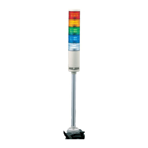
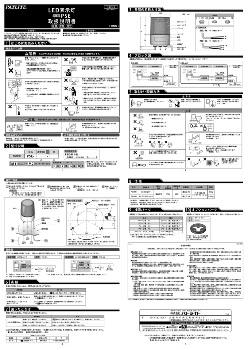
Patlite LCE-A User manual

取扱説明書
型式:
LCE-A / LCS-A
3.各部の名称
-1-
このたびは、 をお買い上げいただきましてありがとうございます。ご使用
の前にこの取扱説明書をよくお読みのうえ、正しくお使いください。また、本書は大切に保管してくださ
い。保守・点検や補修などをするときには、必ず本書を読み直してください。なお、ご不明な点は最終
ページに記載の技術相談窓口へお問い合わせください。
●配線時、必ず電源を切っておこなってください。ショートによる内部回路の焼損や感電の危険があります。
●LEDユニットなど補修をされる際は感電防止のため、必ず電源を切ってからおこなってください。
●LEDユニット・ヘッドカバーを外したままや、割れたままでの放置・使用をしないでください。感電など非常に危険です。
●工事を伴う設置は必ず専門業者へ依頼してください。感電・火災・落下などの危険があります。
●本製品を安全重視の保安目的でご使用される場合には必ず日常点検を実施し、万一の不具合・故障発生時のために、他の機器
との併用をおこなってください。
●本製品を機械等に取り付けたあと本製品を掴んで機械に登ったり、機械のカバーを外す際本製品に引っ掛けたりしない様に
充分注意してください。転倒・落下などの原因となり非常に危険です。
警告
●LEDユニットなどの補修部品は、必ず本書に記載されております指定部品をご使用ください。
●電源には「配線例」に示す外部ヒューズを安全のために必ず入れてください。
●他の製品のユニットとの組替えはおこなわないでください。故障の原因となります。
1.安全のため必ずお守りいただきたいこと
注意
安全上のご注意
お使いになる人や他の人への危害、財産への損害を未然に防ぐため、必ずお守りいただくことを、次のように説明しています。
■表示内容を無視して誤った使い方をした時に生じる危害や損害の程度を、次の 表示 で区分し説明しております。
警告
注意
この表示の欄は「死亡または重傷などを負う可能性が想定される」内容です。
この表示の欄は「傷害を負う可能性または物的損害のみが発生する可能性が想定され
る」内容です。
2.呼称表示
●ポール仕様 ●直付け仕様
センタ-ねじ
ヘッドカバ-
LEDユニット
ボリュ-ム
ポ-ルブラケット
防水パッキン
ポール
ボディ
信号線
電源線
[LCE-A型]
センタ-ねじ
ヘッドカバ-
LEDユニット
ポール
ボディ
信号線
電源線
[LCS-A型]
■定格電圧
02
:AC/DC 24V
M2:AC90~250V
■取り付け方法
W:直取付け
無:ポール取付け
■段数
1~5段式
■点灯方式
FB:点灯・点滅・ブザー
無
:点灯
■点灯色
R:赤
Y:黄
G:緑
B:青
C:白
■グローブ色
無:色つき
Z:クリア
■段数
1~5段式
■点灯色
R:赤
Y:黄
G:緑
B:青
C:白
■グローブ色
無:色つき
Z:クリア
■定格電圧
02:AC/DC 24V
LCE
-
A
-
LCS
-
02A
-
B95100295 L

5.取付け方法
(単位:mm)
φ30
3-120°
コード取出し穴φ12
取付穴
3-φ4
5
銘板位置
注意
● 本製品は屋内のみ使用可能です。(屋外不可)
● 横向き・逆取付けは避けてください。
● 直流、交流および使用電圧を間違えないよう確かめてからご使用ください。
● LEDユニットを外したままの放置、使用はしないでください。
● LEDユニットやボディの汚れは、水を含ませたやわらかい布で拭いて
ください。(シンナー・ベンジン・ガソリン・油などで拭かないでください)
● 取付け時、ヘッドカバーおよびLEDユニットに回転方向の力を加えないで
ください。
● 製品取付けの時、防水パッキンを外さないようにしてください。防水構造に
支障をきたします。
● 本製品の取付部には厚み1mmの防水用のパッキンがついておりますが、取付面
の凹凸が大きく防水性が保てない場合、本製品と取付面との隙間を防水シール
剤等でシール処理してください。
● Type 1 Enclosure 平面取付用途でご使用してください。
● LCE-□02A(FB)(W)型をご使用の際は、最大周囲温度40℃の条件でご使用して
ください。LCE-□M2A(FB)(W)型,LCS-□02A型をご使用の際は、最大周囲温度
60℃の条件でご使用してください。
※上記注意事項に反したお取扱いおよび改造や天災などによって生じた故障に
ついては保証できません。また、本書に記載したこと以外の使い方はしない
でください。
[取付け方法]
●取付け部分へ取付け穴の加工をおこなってください。
●ボルト、ナット類を用いて固定してください。
●取付はなるべく振動が小さく十分強度のある場所へ正方向に取付けてください。
●FB(点灯・点滅・ブザー)仕様の場合、方向により音圧が変わりますので取付け前に方向を確認してください。
この型紙の取り扱い方法
1.製品の穴位置を確認する。
2.テープなどで型紙を取り付け面などに固定
する。
3.取り付け面にポンチなどで印を付ける。
4.ドリルなどで取り付け面に穴加工する。
※銘板の方向及びコードの取り出し口を決定
してから穴加工してください。
ブザ-
発音方向
4.寸法
[LCE-□□□A(FB)/LCS-□02A型]
ボルト(M8) ナット(M8)
取付アングル
取付穴2-φ9取付面
ナット(M17, P=1.5)
取付穴(φ18)
20
●平面取付●側面取付
[LCE-□□□A(FB)W型]
-2-
2-φ9
R20
57
2720
17
11
32
φ17.3
R20
30
44.5
2-φ4.2
(単位:mm)
[LCE-□02AFB(W)型/LCE-□M2A(W)型] [LCE-□M2AFB(W)型] [LCS-□02A型]
1150
35
φ40
11
1段式 61
32
(264) 18
φ17.2
5段式 201
4段式 166
3段式 131
2段式 96
[付属品L型金具寸法]
1400
1100
35
φ40
11
1段式 158
12 111
1段式 158
(257.5)
27
φ17.2
5段式 298
3段式 228
4段式 263
2段式 193
5段式 298
4段式 263
3段式 228
2段式 193
取付可能板厚 10
(13)
1350
950
35
φ40
11
12 167
1段式 213
27
φ17.2
5段式 353
3段式 283
4段式 318
2段式 248
取付可能板厚 10
(13)
(257.5)
1段式 213
5段式 353
3段式 283
4段式 318
2段式 248
3-M3(P=1.5) 3-M3(P=1.5)

1.配線例
6.配線方法
[配線例]
(※印についてはUL規格に対応する場合の条件を記載しています。)
●配線例に従って配線してください。
●5段以下の配線については配線例に習って各段毎に
外部接点を増減し配線してください。
●同色のLEDユニットを複数使用する際は接点容量
を「同色LEDユニット数×1段当たりの接点容量」
としてください。(1本の信号線で同色のLEDユ
ニットが点灯するため)
※電源側には必ず接点から305mm以内に外部接点保護用
ヒューズを入れてください。
●配線完了後、使用しないリード線の先端は必ず絶縁テ
ープなどで1本ずつ絶縁処理してください。
●
接続する電源には必ず”クラス2回路”を使用してください。
※また、ヒューズホルダーについてはUL規格認定品
をご使用ください。
ご使用になるヒューズは、製品を取付ける機械の定
格にあったヒューズをご使用ください。
※AC90~250V仕様については緑/黄リード線を必ず
アースにつないでください。
●複数台の同時使用や、その他の特殊な使い方でご不明
な点がございましたら、配線前に技術相談窓口へお問
い合わせください。
【LCE-□02A(FB)(W)/ LCS-□02A型 外部接点容量】
赤・黄:27.2mA 緑・青・白:15.2mA
Is≧100mA Vs≧35V AC
40mA
250mA
Is≧300mA Vs≧35V AC
350mA
Is≧500mA
Vs≧35V AC
【信号線配色一覧】
※5色(5本)の信号線は段数に関係なく
本体より取り出されています。
※ブザー仕様でないものには信号線が
でていません。
【外部接点保護用ヒューズ】
LEDユニット色
赤色
黄色
緑色
青色
白色
対応信号線配色
赤信号線
橙信号線
緑信号線
青信号線
白信号線
ブザー
なし
ブザー1:ピ・ピ・ピ・・・
ブザー2:ピーピーピー・・
対応信号線配色
紫信号線
空信号線
電圧
全電圧仕様
ヒューズ定格電流
250V 1A
※ご使用になるヒューズは製品を取付ける
機械の定格にあったヒューズをご使用く
ださい。(例.クラスJタイプ以上)
LEDユニット
(1段当り)
ブザー
電源
信号線電流
接点容量
信号線電流
突入電流
接点容量
消費電流
接点容量
電圧仕様 AC/DC 24V
●配線は必ず電源を切っておこなってください。ショートによる内部回路の焼損や、感電の危険があります。
●配線時にリード線を引っ張ったり、ポールまたはボディ内に押し込まないでください。
●配線例のように、電源側には必ず外部接点保護用ヒューズを入れてください。配線間違いなど万一の場合の電源焼損が
防げます。
●配線は間違いのないよう十分注意しておこなってください。配線を間違うと内部回路が焼損します。
●茶リード線には絶対に電圧印加しないでください。故障します。(FB仕様)
●1つの段(色)で、点灯用と点滅用の外部接点を同時にONさせると、他の段(色)が点灯状態となることがありますので
同時入力を避け、点灯・点滅は切替えをおこなってください。
●点滅仕様でご使用の場合、もしくはブザーを2音ともご使用の場合で複数台を同時作動させている際は、外部接点を各々
独立接点としてください。
●ブザーを2音ともご使用になる場合、表示用外部接点とブザー用外部接点は同一接点とせず各々独立接点としてください。
注意
赤・黄:27.2mA 緑・青・白:15.2mA
Is≧100mA Vs≧35V AC
4.5mA
AC 90~250V
Is≧10mA Vs≧35V AC
電圧仕様
100V:12A / 250V:30A (200μsec)
突入電流値以上の接点
LCE-□02A(W)型/LCS-□02A型
1A
■AC/DC 24V仕様
電圧
電源
LED白 白
LED青 青
LED緑 緑
LED黄 橙
LED赤 赤
電源線 黄
外部保護用
ヒューズ
外部接点
点灯用
■AC 90~250V仕様
電圧
電源
LED白 白
LED青 青
LED緑 緑
LED黄 橙
LED赤 赤
外部接点
点灯用
点灯用共通線 黄
電源線 灰
電源線 黒
アース線 緑/黄
1A
外部保護用
ヒューズ
1A
■AC/DC 24V仕様
電圧
電源
LED白 白
LED青 青
LED緑 緑
LED黄 橙
LED赤 赤
電源線 黄
外部保護用ヒューズ
点滅用外部接点
ブザー2 空
ブザー1 紫
点滅用共通線 茶
電源線 灰
点灯・ブザー用外部接点
1A
■AC 90~250V仕様
LED白 白
LED青 青
LED緑 緑
LED黄 橙
LED赤 赤
点灯用共通線 黄
ブザー2 空
ブザー1 紫
点滅用共通線 茶
電源線 灰
電源線 黒
点滅用外部接点
点灯・ブザー用外部接点
電圧
電源
外部保護用ヒューズ
アース線 緑/黄
LCE-□M2A(W)型
LCE-□02AFB(W)型LCE-□M2AFB(W)型
【LCE-□M2A(FB)(W)型 外部接点容量】
LEDユニット
(1段当り)
ブザー
電源
信号線電流
接点容量
信号線電流
接点容量
突入電流
接点容量
※Is:電流容量、Vs:耐電圧
-3-
※Is:電流容量、Vs:耐電圧
※ブザー1と2が両方とも入力された場合、
ブザー1が優先して鳴ります。

●LCE-□□□A(W)型/LCS-□02A型[点灯仕様]
NPNトランジスタ(24V仕様) PNPトランジスタ(24V仕様)
1A
1A
●LCE-□□□AFB(W)型[点灯・点滅・ブザー仕様]
1A
型式
電源容量
トランジスタ(NPN又はPNP)Vc≧35V
IL≦0.1mA
Ic≧100mA(LEDユニット)
Ic≧300mA(ブザー)
耐電圧
漏れ電流
2.NPN / PNP トランジスタ駆動の場合
LED白 白
LED青 青
LED緑 緑
LED黄 橙
LED赤 赤
電源線 黄
ヒューズ
点灯用
I/Oユニット
DC 24V
電源
電源線 黄
LED白 白
LED青 青
LED緑 緑
LED黄 橙
LED赤 赤
点灯用
I/Oユニット
ヒューズ
DC 24V
電源
1A
ヒューズ
DC 24V
電源
LED白 白
LED青 青
LED緑 緑
LED黄 橙
LED赤 赤
電源線 黄ヒューズ
点灯用
I/Oユニット
電源
I/Oユニット
点滅用
ブザ-1 紫
ブザ-2 空
電源線 灰
点灯COM
点滅COM 茶
点滅COM 茶
電源線 灰
電源線 黄
点灯COM
LED白 白
LED青 青
LED緑 緑
LED黄 橙
LED赤 赤
ブザ-1 紫
ブザ-2 空
点灯用
I/Oユニット
I/Oユニット
点滅用
DC 24V
LED
ユニット A
7.ユニット(色)配列組替え方法
●組換え作業は、必ず電源を切ってからおこなってください。
●ヘッドカバー中央のねじをゆるめて、ヘッドカバーを外してください。
●上下のLEDユニットは中央のリブ(A部)により位置決めされているので、
A部の位置を合わせておこなってください。
●LEDユニットを増段または減段される際は、センターねじ(3.各部の名称)
を各段用のものに取り替えてください。
●無理なLEDユニットの脱着はおこなわないでください。破損する恐れ
があります。
●ねじをゆるめた状態ではLEDユニット・ヘッドカバーがはずれやすい
ため、落下して破損することのないよう取扱いに注意してください。
●LEDを手でゆがめたり、破損させないようにしてください。
●センターねじの締め過ぎにご注意ください。破損の恐れがあります。
(締付けトルクは0.39N・mを目安としてください。)
注意
※点灯・点滅仕様の場合、それぞれ別のI/Oユニットが必要となります。
LED白 白
LED青 青
LED緑 緑
LED黄 橙
LED赤 赤
点灯用共通線 黄
点灯用
I/Oユニット
I/Oユニット
点滅用
ブザ-1 紫
ブザ-2 空
点滅用共通線 茶
LED白 白
LED青 青
LED緑 緑
LED黄 橙
LED赤 赤
点灯用共通線 黄
点灯用
I/Oユニット
アース線 緑/黄
黒リード線
灰リード線
電源
外部保護用
ヒューズ
1A
黒リード線
灰リード線
電源
外部保護用
ヒューズ
1A
NPNトランジスタ(90~250V仕様)
NPNトランジスタ(24V仕様) PNPトランジスタ(24V仕様)NPNトランジスタ(90~250V仕様)
アース線 緑/黄
-4-

●この取扱説明書に記載した警告事項・注意事項に反したお取扱いにより発生した故障や損害などについては、責任を
負いかねますのでご了承願います。
●寸法・仕様および構造などは、改善のため予告なく変更することがありますので、御了承ください。
注意
9.CEマーキング仕様として使用される場合の注意
10.仕様
●ヒューズは必ずIEC127認定品のものをご使用ください。
●ポール取付けなどで、本体から外部にリード線が露出する場合は必ずビニールチューブなどでニ重絶縁保護をしてください。
MAXMIN
VOL.
●無理にボリュームを動かさないでください。破損する恐れがあります。
8.音量調節方法
●音量調節作業はボリューム(「3.各部の名称」参照)
を左右に動かすことによっておこなってください。
●ボリュームはツマミが右側で最大音量となります。
ボディ
ブラケット
ボリュ-ム
注意
-5-
1段式
2段式
3段式
4段式
5段式
段数 型式
-1M2A(W)
-1M2AFB(W)
-2M2A(W)
-2M2AFB(W)
-3M2A(W)
-3M2AFB(W)
-4M2A(W)
-4M2AFB(W)
-5M2A(W)
-5M2AFB(W)
入力電圧 定格消費電力 質量※
0.60kg(0.24kg)
0.65kg(0.29kg)
0.63kg(0.27kg)
0.68kg(0.32kg)
0.66kg(0.30kg)
0.71kg(0.35kg)
0.69kg(0.33kg)
0.74kg(0.38kg)
0.72kg(0.36kg)
0.77kg(0.41kg)
点滅回数・音圧 線種/線径
電源線
UL1015/AWG18
信号線
UL1007/AWG22
FB仕様
点滅回数
60回/分
音圧レベル
70~85dB(at 1m)
AC90~250V
(50/60Hz)
[LCE-□M2A(FB)(W)型]
※( )内はポール無し仕様[W仕様]の質量
AC 240V時
赤・黄
緑・青
・白:1.9W
ブザー:1.7W
※( )内はポール無し仕様[W仕様]の質量
電源線
信号線
UL1007/AWG22
AC/DC 24V
(50/60Hz)
FB仕様
点滅回数
60回/分
音圧レベル
70~85dB
(at 1m)
[LCE-□02A(FB)(W)型]
1段式
2段式
3段式
4段式
5段式
段数 型式
-102A(W)
-102AFB(W)
-202A(W)
-202AFB(W)
-302A(W)
-302AFB(W)
-402A(W)
-402AFB(W)
-502A(W)
-502AFB(W)
入力電圧 質量※
0.52kg(0.16kg)
0.58kg(0.22kg)
0.55kg(0.19kg)
0.61kg(0.25kg)
0.58kg(0.22kg)
0.64kg(0.28kg)
0.61kg(0.25kg)
0.67kg(0.31kg)
0.64kg(0.28kg)
0.70kg(0.34kg)
点滅回数・音圧 線種/線径
[LCS-□02A型]
型式 定格電圧 質量 線種/線径
リード線
UL1007
AWG22
AC/DC 24V
(50/60Hz)
0.42kg
0.45kg
0.48kg
0.51kg
0.54kg
1段式
2段式
3段式
4段式
5段式
段数
-102A
-202A
-302A
-402A
-502A
UL登録モデル
LCE-_02A(W)
LCE-_02AFB(W)
LCE-_02A(W)
LCE-_02AFB(W)
LCE-_02A(W)
LCE-_02AFB(W)
LCE-_02A(W)
LCE-_02AFB(W)
LCE-_02A(W)
LCE-_02AFB(W)
UL登録モデル
LCE-_M2A(W)
LCE-_M2AFB(W)
LCE-_M2A(W)
LCE-_M2AFB(W)
LCE-_M2A(W)
LCE-_M2AFB(W)
LCE-_M2A(W)
LCE-_M2AFB(W)
LCE-_M2A(W)
LCE-_M2AFB(W)
UL登録モデル
LCS-_02A
待機電力
AC100V/120V
時
:0.7W
AC220V/240V
時
:1.1W

-6-
注) この保証書は本書に明示した期間・条件のもとで無償修理または交換をお約束するもので、お客様の法律上の
権利を制限するものではありません。
製品保証規定
[Ver.2.0(2014.06.01)]
この保証規定は、お客様がお買い上げ頂いた製品に関して、
株式会社パトライト(以下、「弊社」といいます)が保証する
内容について明記しています。
第1条(目的)
1.本規定は、弊社の製品(以下、「本製品」といいます)に
関する保証責任の取扱いについて定めるものとします。
2.お客様が本製品の使用を開始された時点で、お客様は本
規定に同意して頂いたものとし、お客様と弊社との間で本
規定の効力が有効に生ずるものとします。
第2条(保証対象および保証期間)
弊社は、お客様が本製品を購入された日から1年以内(以
下、「保証期間」といいます)に本製品について以下の各号の
いずれかに該当した場合(以下、「不良」といいます)、次条
に定める保証責任を負うものとします。
①本製品の外形または内部に本製品の用途または機能を損
なう変質または変形が発生した場合
②本製品が製品仕様書に定められた性能を発揮しない場合
第3条(保証内容)
1.弊社は、本製品に不良が生じた場合(以下、「不良品」と
いいます)、自らの裁量によって無償による修理または代替
品の提供のいずれかの措置を講じるものとします。
2.弊社が前項の措置を講じた場合、当該措置がなされた本
製品の保証期間は、当初の不良品に関する保証期間と同一
とします。
3.弊社が第1項に基づきお客様に対して本製品の代替品の
提供を行った場合、弊社において回収致しました不良品の
所有権は、弊社に帰属するものとします。
4.弊社は、第1項の代替品の提供に関して、製造中止等の
諸事情により同一製品を提供できない場合には、自らの裁
量により本製品と同等以上の性能を有する製品を提供でき
るものとします。
5.以下の各号の部材は、保証の対象外とします。
①消耗品(モータ・電球・ロータゴム・パッキン・Oリ
ング・キセノン基板等)
②輸送中における本製品の保護を目的とした梱包材料
(製品梱包箱・ビニール袋・緩衝材等)
第4条(免責事項)
1.弊社は、以下の各号のいずれかに該当する場合、不良に
関して前条に定める保証責任を負わないものとします。
①本製品の輸送・運搬中に発生した衝撃・落下等の外部
的要因により不良が発生した場合
②本製品の製品仕様書・取扱説明書・取り扱い上の注意
等に違反することにより不良が発生した場合
③本製品が設置または接続された装置・機器・車両・船
舶・建造物・ソフトウェア等による外的要因に起因し
て不良が発生した場合
④お客様または第三者が事前に弊社の承諾を得ることな
く本製品の分解・改造・補修・付属品取付等を行った
ことにより不良が発生した場合
⑤お客様または第三者の故意または過失により不良が発
生した場合
⑥お客様が第5条第3項の禁止事項に違反した結果、不
良が発生した場合
⑦火災・地震・台風・落雷等の天災地変または公害・塩
害・静電気・停電・異常電圧等の外部的要因に起因し
て不良が発生した場合
⑧本製品の販売時点における科学または技術に関する知
見によっては、弊社が不良を予測することができない
場合
⑨通常使用に基づく本製品の自然消耗または経年劣化に
より不良が発生した場合
⑩本製品が日本以外の国において使用されたことにより
不良が発生した場合
⑪保証期間の満了後に不良が発生し、お客様において当
該不良が保証期間内に発生したことを証明することが
できない場合
⑫弊社に対して本書のご提示がない場合
2.弊社は、第3条第1項の措置の実施の有無を問わず、不
良に起因してお客様に生じた通常損害、特別損害、機会損
失、逸失利益、事故補償、当社製品以外の製品(本製品と
通信回線等により接続されているか否かを問いません)に
関する損傷、損失、不具合、データ損失および不良を修補
するための費用(人件費、工事費、交通費、運送費等をい
いますが、これらに限られません)のいずれに関しても、
一切の責任を負わないものとします。
3.お客様が使用されるシステム・機械・装置等への本製品
の適合性はお客様自身でご確認いただくものとし、弊社は
これらと本製品との適合性について一切の責任を負わない
ものとします。
第5条(ソフトウェアの取扱い)
1.本製品に弊社が著作権者であるソフトウェア(以下、「本
ソフトウェア」といいます)が内蔵されている場合、弊社
は、お客様に対して本ソフトウェアを日本国内で使用する
非独占的で譲渡不能な使用権を許諾するものとします。
2.弊社は、本ソフトウェアの機能を向上させるべく、自ら
の裁量により本ソフトウェアをバージョンアップするこ
とができるものとします。弊社は、ソフトウェアのバージ
ョンアップに起因してお客様に生じた通常損害、特別損害、
機会損失、逸失利益、事故補償、当社製品以外の製品(本
製品と通信回線等により接続されているか否かを問いま
せん)に関する損傷、損失、不具合、データ損失および不
良を修補するための費用(人件費、工事費、交通費、運送
費等をいいますが、これらに限られません)のいずれに関
しても、一切の責任を負わないものとします。
3.お客様は、事前に弊社の承諾を得ることなく、以下の各
号の行為を行ってはならないものとします。
①本ソフトウェアを複製すること
②本ソフトウェアの改変・結合・リバースエンジニアリ
ング・逆コンパイル・逆アセンブル等を行うこと
③本ソフトウェアを第三者に対して再使用許諾・貸与・
レンタル・転売すること
④本ソフトウェアを第三者に送信可能な状態でネットワ
ーク上に蓄積すること
⑤本ソフトウェアに付されている著作権表示およびその
他の権利表示を除去すること
第6条(その他)
1.本製品に関する製品仕様書・取扱説明書・カタログ等の
記載内容は、事前に予告なしに変更する場合があります。
2.本製品に関する弊社の責任は、本規定をもって全てとし、
弊社はこれ以外に一切の責任を負わないものとします。
3.本保証書は、日本国内においてのみ有効に効力を生ずる
ものとします。お客様または第三者が本製品を海外へ輸出
される場合、本規定の適用は除外されるものとし、本製品
に関する全ての責任は、輸出元に帰属するものとします。
4.弊社は、お客様による紛失・損傷等の事由を問わず、お
客様に対して本書の再発行を行わないものとします。
5.本書は、本書に明示した条件に基づき保証をお約束する
ものです。従って、本書によって弊社およびそれ以外の事
業者に対するお客様の法律上の権利を制限するものではあ
りません。
第7条(準拠法および管轄裁判所)
本規定は、日本法を準拠法とし、日本法に従って解釈され
るものとします。本規定の履行および解釈に関して紛争が生
じたときは、大阪地方裁判所を第一審の専属的合意管轄裁判
所とするものとします。
以上
大阪府大阪市中央区本町 4 丁目 4 番 25 号
株式会社パトライト

INSTALLATION MANUAL
Model : LCE
-
A / LCS-A
Signal Tower
2. Model No. Configuration
3. Part names
●Pole mount ●Direct mount
Body
Power source wire
Lead wire
Pole
Pole bracket
Head cover
Screw
LED unit
Waterproof sheet
Volume
Thank you for specifying the PATLITE Signal Tower for your application. Please read these instructions carefully before
you perform installation, maintenance and repair. Store this manual carefully for easy reference. If you have any
questions about this product, please contact PATLITE Corporation.
1. To operate this product safely, please observe the following
●Make sure the power is OFF before wiring. Wrong wiring may result in a cause of short circuit or electric shock.
●Do not use this product with the lens damaged or removed, or without the head cover in or order to avoid an electric shock.
●If installing this product requires construction work, pleaseask a specialist in order to avoid electric shock, fire, or personal injury.
●When this product is used for security purposes, it should be inspected daily. In case a malfunction should occur,
it is recommended that you use this product together with other security products.
●Do not use this product to support your weight while climbing onto a machine. Mount the product so that it is clear of any
moving parts - such as a machine cover.
Warning
●Concerning replacement parts, such as LED unit, etc. be sure to use those specified in this manual.
●For safety, make sure to connect an external fuse to the power source as shown in the wiring example.
●Do not substitute parts of units from other products as this may cause a breakdown.
Caution
NOTES TO BE OBSERVED FOR SAFE OPERATION
In order to prevent any damage to the user and other personnel or to assets, note the following:
■The indications for warning are divided into the following classes according to the degree of danger or
damage incurred when the warning is not taken into consideration and the product is not correctly used.
Warning
Caution
Indicates an imminently dangerous condition: failure to follow
the instructions may lead to death or serious injury.
Indicates a potentially dangerous condition: failure to follow
the instructions may lead to slight injury or property damage.
■Rated voltage
02:24V AC/DC
■Light style
1~5 Light style
LCS
-
02A
-
■Color of LED
R: Red
Y: Amber
G: Green
B: Blue
C: White
■Color of lens
Z : Clear lens
Blank: Color lens
■Light method
FB: Continuous light or flashing, with Buzzer
Blank: Continuous light
■Rated voltage
02
:AC/DC 24V
M2:AC90~250V
■Light style
1~5 Light style
■Installation method
W: Direct mount
Blank: Pole mount
■Color of LED
R: Red
Y: Amber
G: Green
B: Blue
C: White
■Color of lens
Z : Clear lens
Blank: Color lens
LCE
-
A
-
[LCS-□02A Type]
Body
Head cover
Screw
LED unit
Pole Lead wire
[LCE-□□2A(FB) Type]
-7-

-8-
(Unit:mm)
Using this template
1. Confirm the hole position on the product.
2. Secure the template to the installation surface
using adhesive tape.
3. Mark the installation holes using a nail punch,
etc.
4. Drill the holes in the installation surface.
※Confirm the direction of the name plate and the
wiring route before you drill the holes.
φ30
3-120°
Wiring thru
hole φ12
Installation
hole 3-φ4
5
Name plate
position
Buzzer transmission
direction
5. Installation
[Mounting]
●Drill mounting holes in the wall or panel. (See the following installation diagram.)
●Secure the side mounting bracket with hex bolts and hex nuts (not supplied) .
●Install the Signal Tower vertically at a location that has sufficient strength and minimal vibration.
●With buzzer models, the alarm can be heard best from the front direction.
Therefore, make sure the Signal Tower is facing the correction direction before installation.
●This product can be used only indoors. (Do not use it outdoors.)
●Do not install the Signal Tower sideways or inverted.
●Make sure of the specified operating voltage and current before use.
●Do not leave the product or use it without LED unit installed.
●Use the soft cloth with moisture when the LED unit or bodies must be cleaned
up. (Do not use thinner, benzine, gasoline or oil.)
●When installing this product, do not twist the product with excessive torque or
the product may be damaged.
●
During installation, do not remove the waterproof sheet. It may cause a malfunction.
●This product has 1mm thick waterproof packing at the bottom of the pole
bracket. However, when complete waterproofing is not provided due to the
unevenness of the installation surface, apply waterproof sealant between
the unit and the installation surface to maintain waterproof conditions.
●For use on a flat surface of a Type 1 Enclosure.
●
For the model LCE-□02A(FB)(W), maximum surrounding air temperature is at 40℃.
For the model LCE-□M2A(FB)(W), LCS-□02A, maximum surrounding air
temperature is at 60℃.
※Warranty is not valid for malfunctions that are caused by handling that does
not observe the caution instructions, unauthorized modifications or natural
calamities. Do not use this product for purposes other than those specified
in this manual.
Caution
Panel board maximum
installable thickness : 10
1400
1100
35
φ40
11
12 111
(13)
1-Light 158
(257.5)
27
φ17.3
5-Lights 298
3-Lights 228
4-Lights 263
2-Lights 193
2-φ9
R20
572720
17
11
32
φ17.3
R20
30
44.5 2-φ4.2
(Unit : mm)
4. Dimensions
1350
[LCE-□M2AFB(W)Type][LCE-□02A(FB)(W)Type / LCE-□M2A(W)Type]
[Accessory
:L-angle dimension]
1-Light 158
5-Lights 298
3-Lights 228
4-Lights 263
2-Lights 193
950
35
φ40
11
12 167(257.5)
27
φ17.3
1-Light 213
5-Lights 353
3-Lights 283
4-Lights 318
2-Lights 248
[LCE-□□□A(FB)Type / LCS-□02A Type]
Hex bolt(M8) Hex nut(M8)
Mounting
bracket Mounting hole
2-φ9
Flat surface
Hex nut(M17, P=1.5)
Mounting hole
(φ18)
20
●Side Mounting Installation ●Flat Surface Installation [LCE-□□□A(FB)W Type]
Panel board maximum
installable thickness : 10
(13)
1150
35
φ40
11
1-Light 61
18 11
(264)
φ17.2
5-Lights 201
4-Lights 166
3-Lights 131
2-Lights 96
[LCS-□02A Type]
1-Light 213
5-Lights 353
3-Lights 283
4-Lights 318
2-Lights 248
3-M3(P=1.5) 3-M3(P=1.5)

-9-
Is≧100mA Vs≧35V AC
40mA
250mA
Is≧300mA Vs≧35V AC
350mA
Is≧500mA
Vs≧35V AC
1. Wiring example
External contact
for Flashing
External contact
for Continuous
【LCE-□02A(FB)(W)Type / LCS-□02A Type : External contact capacity】
LED unit
(1 Light)
Buzzer
Power supply
Current consumption
Contact capacity
Current consumption
Inrush current
Contact capacity
Current consumption
Voltage specs. 24V AC/DC
Red・Amber:27.2mA Green・Blue・White:15.2mA
Contact capacity
6. Wiring Procedure
[Wiring procedure]
(
Concerning the mark ※, the conditions about the product
corresponding to UL are mentioned.)
●Please make wiring connection according to wiring example.
●For wiring of 5 layers or less, please make wiring connection
by increasing or decreasing external contacts in each layer
according to wiring example.
●When using multiple LED units of the same color, make the
contact capacity equal to the number of same color LED
units multiplied by the contact capacity for 1 light.
(This is because LED units of the same color light up for one
signal line.)
※Fuse for protection of external contact should be installed
within 305mm from the connected point of the power
source wire.
●When wiring is completed, insulate the end of each unused
lead wire by using insulation tape.
●Use Class 2Circuit for the power supply source.
※Use concerning fuse and fuse-holder, be sure to use the products
authorized by UL Inc.
※Use the fuse conforming to the rated current of the machine
which you install product. (Example : Class J type fuse)
※For the 90-250V AC models, connect the green / yellow
lead wire to the ground.
●If you have any questions about simultaneous use of multiple
units or other special operations, contact PATLITE Customer
Service before wiring.
【Wire color table】
※All 5 wires (Red, Orange, Green, Blue, White)
are connected regardless of the number of
LED units.
White Wire
Blue Wire
Green Wire
Orange Wire
Red Wire
White Unit
Blue Unit
Green Unit
Amber Unit
Red Unit
LED unit color
Wire color
Wire color
※Non buzzer specs. do not have a lead wire
for the buzzer.
※Non buzzer specs. do not have a lead wire
for the buzzer.
Buzzer
Buzzer1:Pi・Pi・Pi
Buzzer2:Pee・Pee・Pee
Purple
Wire
Skyblue
Wire
Nothing
【External contact fuse】
250V 1A
Voltage Ampere rating of fuse
All model
※Use the fuse conforming to the rated current
of the machine which you install product.
(Example : Class J type fuse)
●Make sure the power is OFF before wiring. A short circuit may damage internal circuits or cause an electric shock.
●Do not pull out the lead wire or push it into the pole or the body.
●Install the external contact fuse on the power supply side as shown in the wiring example in order to prevent burn in case of
a wiring error.
●Enough attention shall be paid for wiring because if there is any mistakes in wiring a circuit may break down.
●Do not apply voltage directly to the brown lead wire. It may cause a breakdown.(FB type)
●Do not connect the yellow lead wire and the brown lead wire. It may damage the internal circuit.
●Simultaneously turning on the external contact for both constant lighting and flashing for the same light (color), may cause
another light (color) to light up. To avoid this, provide separate switches for flashing or continuous lighting.
●When turning on the same function, such as flashing or alarms, for more than one product simultaneously, be sure to use
separate external contacts for each product and function.
●When using both alarm sounds on one product, use separate contacts for the alarms and the lights.
Caution
※Is : Current capacity Vs : Withstand voltage
LCE-□02A(W)Type
1A
■24V AC/DC Type ■90~250V AC Type
1A
1A
■24V AC/DC Type
1A
■90~250V AC Type
LCE-□M2A(W) Type
LCE-□02AFB(W)Type LCE-□M2AFB(W)Type
supply
Power
LED White White wire
LED Blue Blue wire
LED Green Green wire
LED Amber Orange wire
LED Red Red wire
Yellow wire
External
contact fuse
External
contact
Continuous COM
External
contact
LED White White wire
LED Blue Blue wire
LED Green Green wire
LED Amber Orange wire
LED Red Red wire
supply
Power
Yellow wire
Gray wire
Black wire External
contact fuse
Green/Yellow wire
(Connect Graund)
supply
Power
Yellow wire
External
contact fuse
Flashing COM
supply
Power
Yellow wire
Gray wire
Black wire
External
contact fuse
Green/Yellow wire
(Connect Graund)
Gray wire
Brown wire Flashing COM Brown wire
Continuous COM
LED White White wire
LED Blue Blue wire
LED Green Green wire
LED Amber Orange wire
LED Red Red wire
Buzzer2 Skyblue wire
Buzzer1 Purple wire
LED White White wire
LED Blue Blue wire
LED Green Green wire
LED Amber Orange wire
LED Red Red wire
Buzzer2 Skyblue wire
Buzzer1 Purple wire
External contact
for Flashing
External contact
for Continuous
Red・Amber:27.2mA Green・Blue・White:15.2mA
Is≧100mA Vs≧35V AC
4.5mA
Max:25A 200μsec
Is≧10mA Vs≧35V AC
100V:12A 250V:30A (200μsec)
Is≧25A
【LCE-□M2A(FB)(W)Type: External contact capacity】
Inrush current
Current consumption
Contact capacity
Current consumption
Contact capacity
Inrush current
Contact capacity
Voltage specs.
※Is : Current capacity Vs : Withstand voltage
90~250V AC
LED unit
(1 Light)
Buzzer
Power supply
Power supply
※
When buzzer 1 and 2 are connected to
common at the same time,it prioritizes buzzer 1.

-10-
A
2. NPN(PNP)Transistor drive example
●LCE-□□□A(W) Type / LCS-□02A Type[Continuous light type]
Yellow wire
Continuous
I/O Unit
Power Supply
External
contact
Fuse
LED White White wire
LED Blue Blue wire
LED Green Green wire
LED Amber Orange wire
LED Red Red wire
24V DC
Yellow wire
24V DC
LED White White wire
LED Blue Blue wire
LED Green Green wire
LED Amber Orange wire
LED Red Red wire
Continuous
I/O Unit
Power Supply External
contact Fuse
Model
Current capacity
Transistor (NPN or PNP)Vc≧35V
IL≦0.1mA
Ic≧100mA(LED unit)
Ic≧300mA(Buzzer)
Dielectric break
down strength
Leak current
●LCE-□□□AFB(W)Type[Continuous light or Flashing, with Buzzer type]
Flashing
I/O Unit
Continuous
I/O Unit
Power
Supply External
contact Fuse
24V DC
Brown wire
Flashing COM
Gray wire
LED White
White wire
LED Blue
Blue wire
LED Green
Green wire
LED Amber
Orange wire
LED Red
Red wire
Buzzer1
Purple wire
Buzzer2
Skyblue wire
Yellow wire
Continuous COM
LED unit
7. Changing LED unit positions
●Turn the power off before performing this procedure.
●Unscrew the head cover and remove the lens.
●Positions of both up and down LED units are fixed by the central parts(A part). Therefore
please put the A parts of boss sides together to connect the up and down LED units.
●When increasing or decreasing the number of modules, install a new center screw.
(See 3. Part Names.)
Caution
●Do not remove a LED unit forcibly or it may damage the unit.
●Once the center screw is loose or removed, the LED units and the
head cover are unstable. Handle carefully to avoid damage.
●Handle the LED units carefully so they are not warped or damaged
while changing their positions on the tower.
●
When the screw of the head cover is tightened too much, it is likely
to damage it. (The tightening torque is about 0.39N・m.)
※When using FB type, use a separate I/O unit for flashing.
PNP Transistor (24V Type)
1A
1A
1A
1A
Earth wire(Green/Yllow wire)
Black wire
Gray wire
1A
1A
NPN Transistor (90~250V Type)
LED White White wire
LED Blue Blue wire
LED Green Green wire
LED Amber Orange wire
LED Red Red wire
Yellow wire
Continuous COM
Continuous
I/O Unit
Power Supply
External
contact Fuse
NPN Transistor (24V Type)
LED White
White wire
LED Blue
Blue wire
LED Green
Green wire
LED Amber
Orange wire
LED Red
Red wire
Yellow wire
Gray wire
Brown wire
Flashing
I/O Unit
Continuous
I/O Unit
Power
Supply
External
contact
Fuse
Buzzer1
Purple wire
Buzzer2
Skyblue wire
Continuous COM
Flashing COM
24V DC Flashing
I/O Unit
Continuous
I/O Unit
Power
Supply
External
contact Fuse
LED White
White wire
LED Blue
Blue wire
LED Green
Green wire
LED Amber
Orange wire
LED Red
Red wire
Buzzer1
Purple wire
Buzzer2
Skyblue wire
Yellow wire
Gray wire
Continuous COM
Black wire
Brown wire
Flashing COM
PNP Transistor (24V Type)
NPN Transistor 90~250V Type)
NPN Transistor (24V Type)
Earth wire(Green/Yllow wire)

-11-
Power sorce
and
lead wire
UL1007/AWG22
24V AC/DC
(50/60Hz)
10. Specifications
FB Type
60 Flashes
per minute
Sound level
70~85dB(at1m)
●PATLITE Corporation disclaims all liability for any malfunction or damage occurring as a result of handling contrary to
the instructions, cautions and warnings mentioned in this manual.
●Specifications may change without notice due to continual product improvement.
Caution
9. To use this product in accordance with CE marking, please observe the followings
●Please use a fuse specified by IEC 127.
●When lead wires are exposed outside the body during pole installation, etc. always provide double insulation using insulation tape
and vinyl tubing, etc.
MAXMIN
VOL. Volume
Body
Bracket
●Do not move the lever forcibly or it may damage
the volume control.
Caution
●The volume can be adjusted by moving the lever near
the bottom of the base to the left or right.
●The volume is at maximum when the lever is positioned
right side.
8. Volume adjustment
Model
-
1M2A(W)
-
1M2AFB(W)
-
2M2A(W)
-
2M2AFB(W)
-
3M2A(W)
-
3M2AFB(W)
-
4M2A(W)
-
4M2AFB(W)
-
5M2A(W)
-
5M2AFB(W)
Mass※
0.60kg(0.24kg)
0.65kg(0.29kg)
0.63kg(0.27kg)
0.68kg(0.32kg)
0.66kg(0.30kg)
0.71kg(0.35kg)
0.69kg(0.33kg)
0.74kg(0.38kg)
0.72kg(0.36kg)
0.77kg(0.41kg)
Power sorce wire
UL1015/AWG18
Lead wire
UL1007/AWG22
90~250V AC
(50/60Hz)
[LCE-□02A(FB)(W)Type]
[LCE-□M2A(FB)(W)Type]
※( )is mass of the direct mount type[Wtype]
1Light
2Lights
3Lights
4Lights
5Lights
Light style
Rated voltage
Wire type/Dia
Wire type/Dia
Power
consumption
Flashing cycle and
Peak sound level
FB Type
60 Flashes
per minute
Sound level
70~85dB(at1m)
240V AC
Red
Amber
Green
Blue
White : 1.9W
Buzzer
: 1.7W
Standing by
power
consumption
at 100VAC/120VAC
: 0.7W
at 220VAC/240VAC
: 1.1W
Model
-
102A(W)
-
102AFB(W)
-
202A(W)
-
202AFB(W)
-
302A(W)
-
302AFB(W)
-
402A(W)
-
402AFB(W)
-
502A(W)
-
502AFB(W)
Mass※
0.52kg(0.16kg)
0.58kg(0.22kg)
0.55kg(0.19kg)
0.61kg(0.25kg)
0.58kg(0.22kg)
0.64kg(0.28kg)
0.61kg(0.25kg)
0.67kg(0.31kg)
0.64kg(0.28kg)
0.70kg(0.34kg)
※( )is mass of the direct mount type[Wtype]
1Light
2Lights
3Lights
4Lights
5Lights
Light style
Rated voltage
Flashing cycle and
Peak sound level
[LCS-□02A Type]
0.42kg
0.45kg
0.48kg
0.51kg
0.54kg
-102A
-202A
-302A
-402A
-502A
24V AC/DC
(50/60Hz)
Light style
Rated voltage
Model Wire type/Dia
Mass
Lead wire
UL1007/AWG22
1Light
2Lights
3Lights
4Lights
5Lights
LCE-_M2A(W)
LCE-_M2AFB(W)
LCE-_M2A(W)
LCE-_M2AFB(W)
LCE-_M2A(W)
LCE-_M2AFB(W)
LCE-_M2A(W)
LCE-_M2AFB(W)
LCE-_M2A(W)
LCE-_M2AFB(W)
LCE-_02A
(
W
)
LCE-_02AFB
(
W
)
LCE-_02A
(
W
)
LCE-_02AFB
(
W
)
LCE-_02A
(
W
)
LCE-_02AFB
(
W
)
LCE-_02A
(
W
)
LCE-_02AFB
(
W
)
LCE-_02A
(
W
)
LCE-_02AFB
(
W
)
UL Registration Model
LCS-_02A
UL Registration Model

-12- B95100295
‘14.12 NHI L
This manual suits for next models
35
Table of contents
Other Patlite Lighting Equipment manuals

Patlite
Patlite WH-A Series User manual

Patlite
Patlite RFV User manual

Patlite
Patlite LS7 User manual

Patlite
Patlite PES Series User manual

Patlite
Patlite WE-402UB-LAN User manual

Patlite
Patlite RLR User manual

Patlite
Patlite SUPERSLIM ME-A Series User manual

Patlite
Patlite ST-PA-LR6 series User manual

Patlite
Patlite LP8US User manual

Patlite
Patlite LA6 series User manual