Patlite NE-24 Series User manual
4.動作方法
このたびは、 小型表示灯をお買い上げいただきましてありがとうござい
ます。ご使用の前にこの取扱説明書をよくお読みのうえ、正しくお使いください。ま
た、本書は大切に保管してください。保守・点検や補修などをするときには、必ず本
書を読み直してください。なお、ご不明な点は最終ページに記載の技術相談窓口へ
お問い合わせください。
●配線時、必ず電源を切っておこなってください。ショートによる内部回路の焼損や感電の危険があります。
●グローブを外したままや、割れたままでの放置・使用をしないでください。感電など非常に危険です。
●工事を伴う設置は必ず専門業者へ依頼してください。感電・火災・落下などの危険があります。
●本製品を安全重視の保安目的でご使用される場合には必ず日常点検を実施し、万一の不具合・故障
発生時のために、他の機器との併用をおこなってください。
●本製品を機械等に取り付けたあと本製品を掴んで機械に登ったり、機械のカバーを外す際本製品に
引っ掛けたりしない様に充分注意してください。転倒・落下などの原因となり非常に危険です。
警告
1.安全のため必ずお守りいただきたいこと
●
電源には「配線例」に示す外部ヒューズを安全のために必ず入れてください。
注意
NE-24-
N E - 2 4 - □
■
点灯色
R:赤, Y:黄, G:緑, B:青, C:白
2. 型式構成
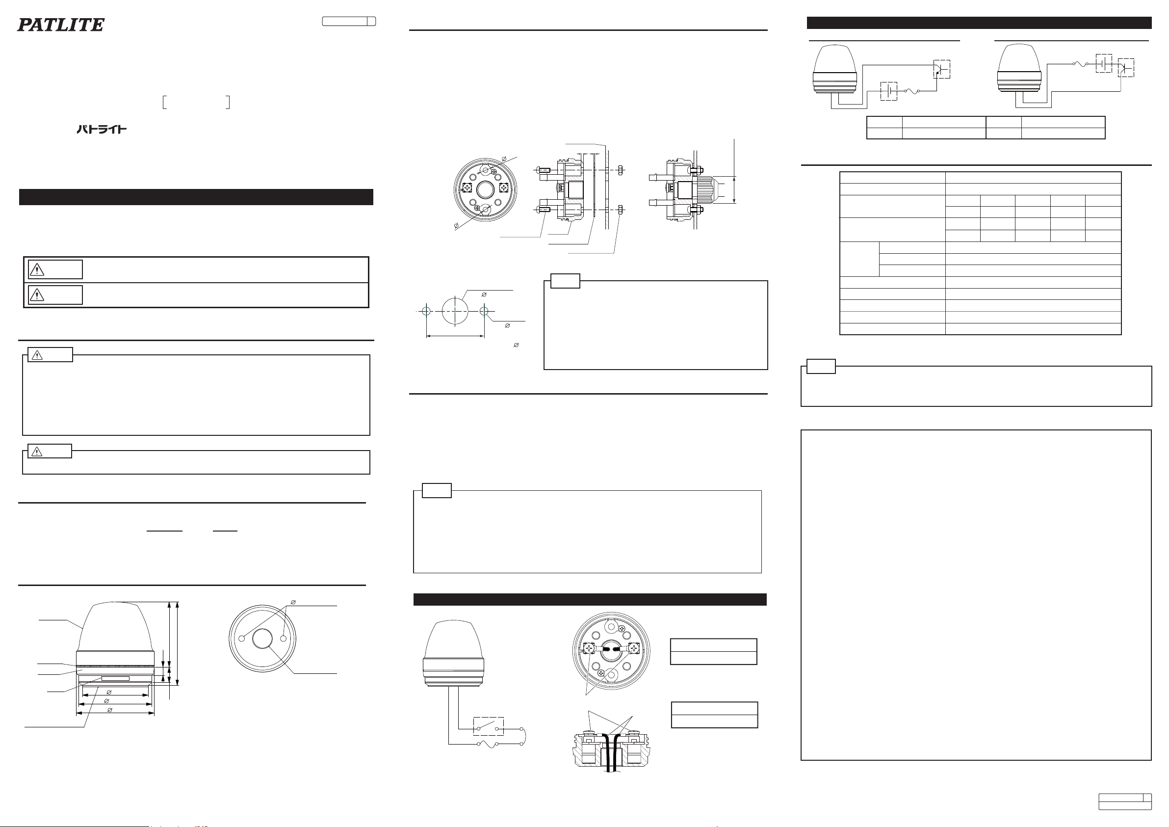
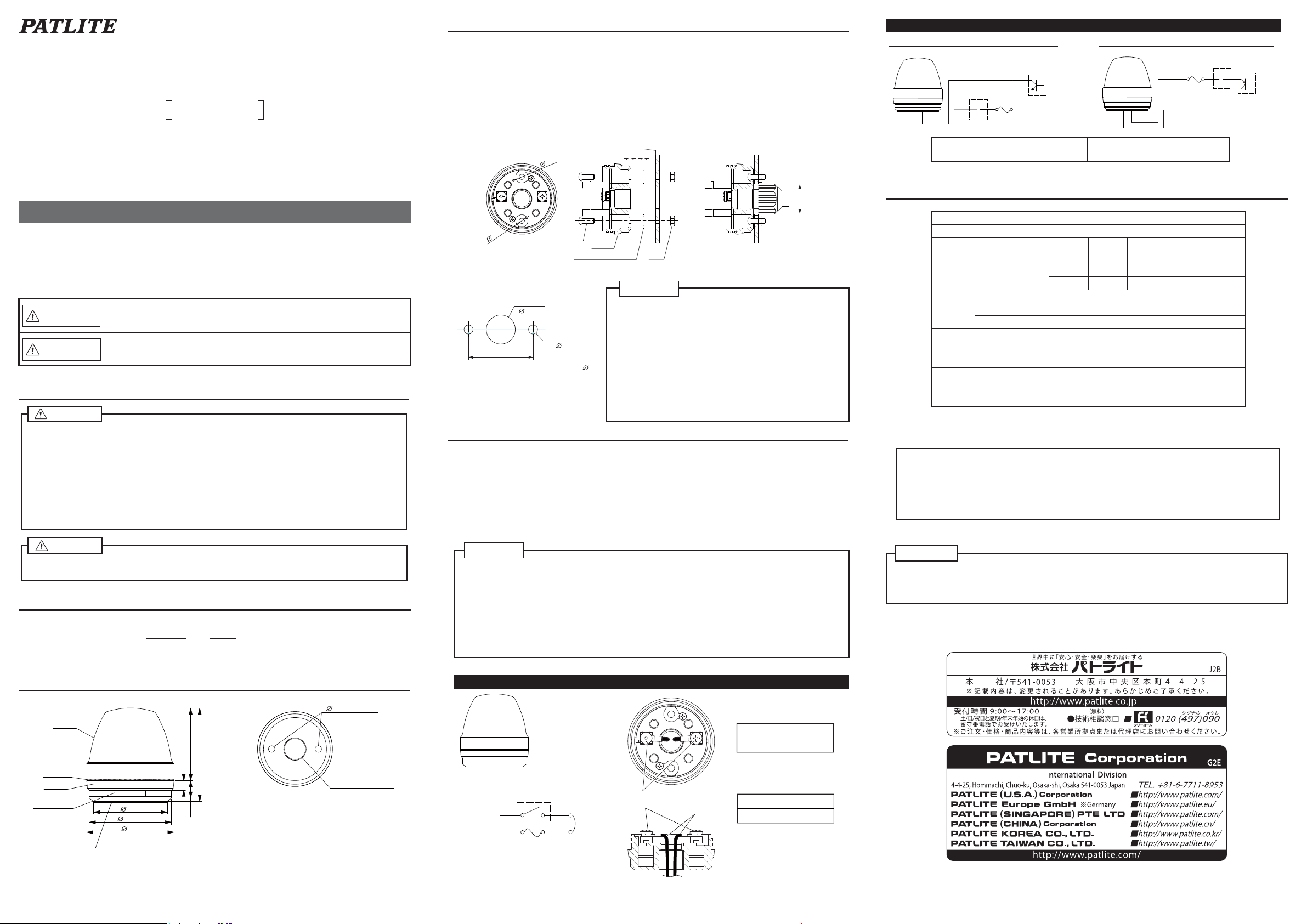
3. 各部の名称と寸法
4. 取付け方法
■取付け手順
① グローブを左方向に回し、ボディから取り外す。
② ボディの取付け用穴を打ち抜く。
③ 防水パッキンの剥離紙をはがし、ボディ底面に貼り付ける。
④ M4ねじ、ナット等を用いて取付け面へ固定する。
(取付け用ねじ類は付属しておりません。別途ご用意ください。)
⑤ グローブを右方向に回し、ボディへ取り付ける。
※取付けはなるべく振動が小さく十分強度のある場所へ取付けてください。
※取付け面裏側の防水が必要な場合は、
・ 取付け面裏側のねじ・ナット類に防水シール処理を施してください。
・ コード取り出し部については、防水シール処理を施すか、防水ケーブルグランドを使用してください。
■取付け面寸法図 [単位:mm]
●本製品は屋内、板取付け専用です。
●グローブを外したままの放置、使用はしないでください。
●グローブやボディの汚れは、水を含ませたやわらかい布で拭い
てください。(シンナー・ベンジン・ガソリン・油などで拭かないで
ください)
●取付けの際は必ず付属の防水パッキンを取り付けてください。
●防水用のパッキンが付属しておりますが、取付面の凹凸が大き
く防水性が保てない場合本製品と取付面との隙間を防水シー
ル剤等でシール処理してください。
コード取出し穴
( 16)*
*ケーブルグランドを使用する場合: 26
35.5
5. 配線方法
1. 配線例
【外部保護ヒューズ】
【外部接点容量】
外部保護用ヒューズ
1A
電源電圧
(無極性)
外部接点
Is≧50mA
Vs≧35V
※Is:電流容量、Vs:電圧容量
●
配線は必ず電源を切っておこなってください
。
ショートによる内部回路の焼損や
、
感電の危険があります。
●直流、交流および使用電圧を間違えないよう確かめてからご使用ください。
●配線時にリード線を引っ張ったり、ボディ内に押し込まないでください。
●配線は間違いのないよう十分注意しておこなってください。配線を間違うと内部回路が焼損します。
●配線例のように、必ず外部接点保護用ヒューズを入れてください。配線間違いなど万一の場合の電源
焼損が防げます。
●グローブを外して配線する際、LEDに力を加えないでください。
●配線先端は必ず丸型端子(推奨:JIS C 2805,RAV1.25-3.5)などで加工してからご使用ください。
注意
6. 仕様
●この取扱説明書に記載した警告事項・注意事項に反したお取扱いにより発生した故障や損害などにつ
いては、責任を負いかねますのでご了承願います。
●寸法・仕様および構造などは、改善のため予告なく変更することがありますので、ご了承ください。
■定格電圧
24:DC 24V
グローブ
ボディ
防水パッキン(t1.0)
Oリング
底面
(防水パッキン取り外し状態)
コード取出し穴
M16×P1.5
取付け用穴 ※1
4.5
※1 取付け用穴(2箇所)は打ち抜き構造に
なっています。ポンチ等で打ち抜いてご
使用ください。
銘板
材質
使用温度範囲(相対湿度)
取付方向
*1) 凸凹のない平面へケーブルグランドを使用して取り付けた場合
保護等級
耐振動性
製品質量
定格電圧
型式
-30℃~+50℃(90%RH以下)
指定なし
IP 65 *1
ABS
PC
グローブ
Oリング シリコンゴム
19.6 m/s2
55g
DC 24V(無極性)
NE-24-□
定格消費電流(最大) 25.9mA 25.9mA 23.0mA 21.8mA 18.4mA
赤黄緑青白
単位:mm
47.5
13.5 61
6.2
48
53.6
57
TYPE :NE
取扱説明書
小型表示灯
安全上のご注意
お使いになる人や他の人への危害、財産への損害を未然に防ぐため、必ずお守りい
ただくことを、次のように説明しています。
■表示内容を無視して誤った使い方をした時に生じる危害や損害の程度を、次の表示
で区分し説明しております。
警告
注意
この表示の欄は「死亡または重傷などを負う可能性される」内容で
す。
この表示の欄は「傷害を負う可能性または物的損害のみが発生す
る可能性が想定される」内容です。
取付け穴
(2- 4.5)
■配線手順
① グローブを左方向に回し、ボディから取り外す。
② ターミナルへ配線する。
③ グローブを右方向に回し、ボディへ取り付ける。
※ ターミナルに極性はありません。
※ コード取出しにケーブルグランドをご使用になる場合は、取付け面側のコード取出し穴径にご注意くださ
い。またケーブルグランドは取付けねじサイズM16×1.5、ねじ長さ11mm以下、外径25mm以下の樹脂
製のものを使用してください。(締め付けトルク:3N・m以下)
※ 電線はAWG24~18を推奨します。
ヒューズ定格
250V1A
※ご使用になるヒューズは製品を
取付ける機械の定格にあった
ヒューズをご使用ください。
(例.クラスJタイプ以上)
注意
注意
定格消費電力(最大) 0.63W 0.63W 0.56W 0.53W 0.45W
赤黄緑青白
ボディ
点灯用
I/Oユニット
点灯用
I/Oユニット
電源
DC24V
電源
DC24V
ヒューズ
ヒューズ
1A
1A
2. 配線例(NPN/PNPトランジスタ駆動の場合)
NPNトランジスタ PNPトランジスタ
型式 トランジスタ(NPN or PNP)
電流容量 Ic ≧50mA Vc ≧35V
耐電圧
漏れ電流 IL ≦0.1mA
取付け参考図
10
4.5
防水パッキン
取付け用ねじ ボディ
取付け面
取付け用ナット
(ケーブルグランド使用時)
25mm 以下
2mm 1mm
※突入電流は発生しません。
製品保証規定
この保証規定は、お買い上げいただいた製品に対して株式会社パトライト(以下弊社)がお客様に保証する内容
について明記しています。
■製品保証について
取扱説明書等の注意書きに基づくお客様の正常なご使用状態のもとで、保証期間内に
万一故障した場合、無償に
て故障箇所の修理または製品の交換をさせていただきます。
製品保証の原則は故障箇所の修理です。
■保証期間
製品はお客様がお買い求めいただいてから12ヶ月間の保証を致します。
保証期間経過後は有償修理扱いとなります。 保証期間内に製品の修理・交換対応があったとしても、保証期
間はその製品のお買い上げ日より12ヶ月間をもって満了となります。
■保証内容について
保証は製品の無償修理または交換に限定され、お客様の故障品調査や作業人件費、
交通費・付属品など、製品
以外に関する費用は保証の対象ではありません。
■保証範囲除外事項
以下の場合、または以下のように見受けられる場合は、製品の無償修理または交換の対象となりません。
・モータ・電球・ロータゴム・パッキン・Oリング・キセノン基板・その他消耗部品の磨耗や寿命の場合
・火災、地震、落雷、塩害、風水雪害、その他天災地変、または異常電圧などによる故障・損傷の場合
・停電、電源・ケーブルなどの故障による電気の切断に起因する故障・損傷の場合
・製品を取付け又は接続しているお客様の装置・機器・車両・船舶などとの間に生じる独特の動作不具合や
故障の場合
・指定環境や推奨環境以外でのご使用により発生する不具合や故障の場合
・製品性能を超える環境やご使用方法により発生する不具合や故障の場合
・お客様の使用上の誤りやお客様が独自に改造・修理・部品交換をされたことに起因する故障・損傷の場合
・交換/取付作業による製品破損(例:物理的破損、静電気によるデバイスなどの損傷)の場合
・輸送・移動時の落下衝撃等、お客様の取扱いが適正でないために生じた故障・損傷の場合
・故意または過失による製品の故障または破損の場合
・製品が日本以外の国で使われている場合
■保証免責事項
お買い上げ製品(ソフトウエアを含む)の故障もしくは動作不具合により直接または間接的に生じた被害・損
害、設備および財産への損害、お客様および関係する第三者の製品やシステムへの損害、顧客からの信用、ま
たはそれらを修復する際に生じる費用(人件費、交通費、復旧費)など、一切の保証は致しかねます。
■責任制限
・弊社の責任範囲は、製品の故障箇所の修理または交換のみに限ります。
従いまして、製品自体または製品の使用から直接または間接的に生じたいかなる損害についても、弊社に
故意または重大なる過失がある場合を除き、一切責任を負うものではありません。
また、弊社が責任を負う場合でも、重大な人身損害の場合を除き、お客様が購入された製品価格を超えて
責任を負うものではありません。
・製品の修理や交換がサービス応答時間内に対処できないことから発生する直接的及び間接的損失または損
害、並びに逸失利益の責任を弊社は負いません。
・弊社が発行する製品取扱説明書その他の文書、または情報に印刷上、事務上、その他誤りまたは記述漏れ
がある場合は、弊社は責任なしに修正することができます。また、そこから発生するあらゆる損失または
損害において弊社は一切責任を負うもの
ではありません。
注) この保証書は本書に明示した期間・条件のもとで無償修理または交換をお約束するもので、お客様の法
律上の権利を制限するものではありません。
Rev.1.3
電線
ターミナルねじ M3
(締付けトルク:0.6N・m以下)
配線参考図
B95100367 J
B95100367
'15.9.UBC J
INSTALLATION MANUAL
Unit:mm
Thank you for specifying the PATLITE Signal Light for your application.
Please read these instructions carefully before you perform installation, maintenance
and repair.Store this manual carefully for easy reference.
If you have any questions about this product, please contact PATLITE Corporation.
1. Safty Precautions
●For safety, make sure to connect an external fuse to the power source as shown in the wiring
example.
Caution
●Make sure the power is off before wiring, repairing, or replacing parts to avoid a short-circuit,
electric shock, or burn.
●Do not use this product with the Lens damaged or removed in order to avoid an electric
shock.
●If installing this product requires construction work, please ask a specialist in order to avoid
electric shock, fire, or personal injury.
●When this product is used for security purposes, it should be inspected daily. In case a
malfunction should occur, it is recommended that you use this product together with other
security products.
●Do not use this product to support your weight while climbing onto a machine. Mount the
product so that it is clear of any moving parts - such as a machine cover.
Warning
2. Model Number Configuration
3. Part Names and outer Appearance
4. Installation
■Installation
(1) Remove the lens turning it to the left.
(2) Punch the two mounting holes on the body.
(3) Paste the waterproof sheet to body, after peel off release paper from the waterproof sheet.
(4) Fix it to the installation board with screws and nuts.(Screws and nuts for installation are not
attached to the product.)
(5) Attach the lens turning it to the right.
●Please select the installation place with enough strength and low vibration.
●When waterproofing of the backside of the installation board is necessary,
(1) Please provide seal coating around the nuts of the backside of the installation board.
(2) Please provide seal coating around the wire exit,or use the cable gland.
●This product can be used only indoors and can be
installed only board. (Do not use it outdoors.)
●Do not leave the product or use it without lens installed.
●Use a soft cloth moistened with water when the lens or
body must be cleaned up. (Do not use thinner, benzine,
gasoline or oil.)
●The waterproof sheet must be used for installation.
●This product has 1mm thick waterproof packing at the
bottom of the Body. However,because installation surface
unevenness may cause a lack of waterproofing
protection,it is recommended to apply waterproof sealant
between the unit and the installation surface to maintain
waterproof conditions
Caution
5.Wiring
■Wiring
(1) Remove the lens turning it to the left.
(2) Connect the wires to the terminal.
(3) Attach the lens turning it to the right.
●The terminals do not have polarity.
●When the cable ground is used, the hole must be the dimension that it can go through.
The cable which it can be used for is as follows; screw size:M16x1.5, screw length:shorter
than 11mm, outer diameter:less than 25mm, material:plastic. (Max. Torque:3N・m)
●Recommended size of wires:AWG24~18.
1. Wiring example
●Make sure the power is off before wiring, repairing, or replacing parts to avoid a short-circuit,
electric shock, or burn.
●Confirm the working voltage of the product.
●Do not pull out the wire or push it into the body.
●Enough attention shall be paid for wiring because if there is any mistakes in wiring a circuit may
break down.
●Install the external contact fuse on the power supply side as shown in the wiring
example in order to prevent burn in case of a wiring error.
●Do not push LED when you make wiring.
●In wiring, the climp-type terminal must be used on the tip of the wires.
Caution
※Inrush current is nothing.
6. Specifications
●PATLITE Corporation disclaims all liability for any malfunction or damage occurring as a result of
handling contrary to the instructions, cautions and warnings mentioned in this manual.
●Specifications may change without notice due to continual product improvement.
Caution
Signal Light
NE-24-
NE-24-□
■Color of LED
R:Red, Y:Amber, G:Green, B:Blue, C:White
■Rated Voltage
24:24VDC
■Installation dimension
TYPE :NE
Safety Precautions
In order to prevent any damage to the user and other personnel or to assets,
note the following:
■The indications for warning are divided into the following classes according to
the degree of danger or damage incurred when the warning is not taken into
consideration and the product is not correctly used.
Indicates an imminently dangerous condition: failure to follow
the instructions may lead to death or serious injury.
Indicates a potentially dangerous condition: failure to follow
the instructions may lead to slight injury or property damage.
Warning
Caution
Lens
Body
Waterproof sheet
(t1.0)
O-ring
Bottom side
(Without waterproof sheet)
Wire exit
M16×P1.5
Mounting holes ※1
4.5
※1 Please punch mounting holes.
Name plate
47.5
13.5 61
6.2
48
53.6
57
unit : mm
Wire exit
( 16)*
35.5
Installation holes
(2- 4.5)
*When the cable ground is used :26
【External Fuse】
【External contact capacity】
External Fuse
Power
supply
(Non-polar)
External contact
I/O unit
I/O unit
Power
supply
24VDC
Power
supply
24VDC
Fuse
Fuse
Is≧50mA
Vs≧35V
※Is:Current capacity
Vs:Voltage capacity
2. Wiring Example(NPN/PNP Transistor drive.)
NPN transistor PNP transistor
Type Transistor(NPN or PNP)
Current capacity Ic ≧50mA
Fuse Rating
250V1A
※Use the fuse conforming to
the rated current of the
machine which you install
product.
(Example : Class J type fuse)
Vc ≧35V
Withstand voltage
Leak current IL ≦0.1mA
Material
Operating temperature range
(Relative humidity)
Mounting direction
Protection rating
Vibration proof
Mass
Rated Voltage
Model
-30℃~+50℃
(Less than 90%RH)
Non-specifed
IP 65 *1
ABS
PC
Lens
O-ring Silicon rubber
19.6 m/s2
55g
24VDC(Non-polar)
NE-24-□
Current consumption(Max.)25.9mA 25.9mA 23.0mA 21.8mA 18.4mA
Red Amber Green Blue White
Power consumption(Max.)0.63W 0.63W 0.56W 0.53W 0.45W
Red Amber Green Blue White
Body
*1)Condition to satisfy IP66/67 : Only when this product is installed on the flat
surface with the cable ground.
Installation example
10
4.5
Waterproof sheet
Screws Body
Installtion board
Nut (When cable ground is used)
Less than 25mm
2mm 1mm
Terminal Screws M3
(Max. Torque:0.6N・m) Wires
Wiring example
This product conforms to EN standard and shows the CE Marking.
This product has been tested and found to comply with the limits for a Class A device,
pursuant to EMC DIRECTIVE.
These limits are designed to provide reasonable protection against harmful interference when the
equipment is operated in a commercial environment.
This product must not be used in residential areas.
Other Patlite Safety Equipment manuals

Popular Safety Equipment manuals by other brands

Lanex
Lanex PB-20 instruction manual

SKYLOTEC
SKYLOTEC ANCHOR ROPES Instructions for use

Besto
Besto Buoyancy Aid 50N Instructions for use

TEUFELBERGER
TEUFELBERGER NODUS Manufacturer's information and instructions for use

Troy Lee Designs
Troy Lee Designs Tbone Product owners manual

Innova
Innova Xtirpa Instruction and safety manual

bolle SAFETY
bolle SAFETY B810 quick start guide

SHENZHEN FANHAI SANJIANG ELECTRONICS
SHENZHEN FANHAI SANJIANG ELECTRONICS A9060T instruction manual

Hiltron security
Hiltron security POWER8E Installation and use manual

Salewa
Salewa MTN SPIKE user manual

Hatco
Hatco B-950P installation guide

Sitec
Sitec TX MATIC operating manual


