Pauli + Sohn EVERYSPACE User manual

Montageanleitung | installation Instructions
Schiebetürsystem für Innenausbau
sliding door system for interior applications
Montageanleitung
installation instructions
Wandmontage / Deckenmontage / Holztür
Glasmontage / Seitenteilmontage / Vor-Zargenmontage
wall mounting / ceiling mounting / wooden door
glass mounting / side panel mounting / front and frame mounting
EVERYSPACE
interior

2
EVERYSPACE interior
Pauli + Sohn GmbH
Industriestraße 20
51597 Morsbach
Telefon: +49(0)22 94-98 03-0
Eisenstraße 2
51545 Waldbröl
Telefon: +49(0)22 91-92 06-0
Stand: 11/2022
www.pauli.de
Versionsnr.: A.1 - Stand: November 2022

3
Montageanleitung | installation Instructions
Allgemeine Hinweise
Beachten Sie die Reinigungs- und Sicherheitshinweise!
Geben Sie diese an den Endverbraucher weiter!
Diese Montageanleitung beschreibt die fachgerechte
Montage des Schiebetürsystem EVERYSPACE von P+S. Für
den EVERYSPACE Schiebetürbeschlag darf nur Glas nach
EN 12150 1:2015 verbaut werden.
Sicherheitshinweise
Halten Sie sich an die Angaben und die Reihenfolge, die
in dieser Montageanleitung enthalten sind.
Zur Montage ist zwingend ein Drehmomentschlüssel
erforderlich!
Fehler bei der Montage können aufgrund der Scheiben-
gewichte zu schweren Verletzungen führen.
Benutzen Sie ein für die bauliche Situation geeignetes
Befestigungsmaterial. Im Zweifelsfall kontaktieren Sie einen
Anwendungstechniker in der Befestigungstechnik.
Beachten Sie die Hinweise der Glashersteller und
verwenden Sie geeignete Anschlagmittel.
Reinigungshinweise
Der Beschlag darf nur mit warmem Wasser und einem
weichen Tuch (z.B. Mikrofaser) feucht abgewischt
und gegebenenfalls nachgetrocknet werden. Scharfe,
aggressive, alkalische oder chlorhaltige Reiniger,
Scheuermittel (z.B. Stahlwolle) oder Lösungsmittel dürfen
nicht verwendet werden. Bei stärkeren Verschmutzungen
(Kalk, Fett, Seifenverschmutzungen) empfehlen wir Ihnen
unser spezielles Reinigungsmittel «Sanfte Pflege» für
Beschläge . Artikel Nr. 8203CTP
General instructions
Observe the cleaning and safety instructions!
Pass them on to the end user!
These installation instructions show the professional
installation of the EVERYSPACE sliding shower door system
from P+S. Only glass according to EN 12150 1:2015 may
be installed with the EVERYSPACE sliding door hardware.
Safety instructions
Adhere to the information and sequence contained within
these assembly instructions.
For assembly, a torque wrench is obligatory!
Errors during assembly can lead to serious injuries due to
the weight of the glass panels.
Use suitable fastening material for the structural situation.
If in doubt, contact an application technician in the fastening
sector.
Observe the instructions of the glass manufacturer and use
suitable equipment.
Cleaning instructions
The hardware may only be wiped with warm water and a
soft cloth (e.g. microfiber) and dried if necessary.
Sharp, aggressive, alkaline or cleaners containing chlorine,
scouring agents (e.g. steel wool) or solvents are not
permitted. For heavier contamination (lime, grease, soap
stains) we recommend our special cleaning agent «Gentle
Care» for hardware. Article No. 8203CTP

4
EVERYSPACE interior
Benötigte Werkzeuge
P Maßband
P Wasserwaage
P Bohrmaschine / Akkuschrauber
P Metallsäge / Kappsäge
P Glassauger / Hebewerkzeuge
P Bitsatz
P Innensechskantschlüssel SW 2,5/3/4/6
P Drehmomentschlüssel 25/14 Nm; SW4/6
P Schlitzschraubendreher 0,5x3
Benötigte Hilfsmittel
P Glasreiniger / Aceton
P Weich PVC Unterlagen verschiedenen Dicken
P Unterlegmaterial, Weich PVC
P Putztücher
P Befestigungsmaterial
Persönliche Schutzausrüstung
P Sicherheitsschuhe
P Handschuhe
P Schutzbrille
Required tools
P measuring tape
P spirit level
P drill / cordless drill
P metal saw / crosscut saw
P glass suction cups / lifting tools
P bit set
P allen keys 2,5/3/4/6mm
P torque wrench 25/14 Nm; SW4/6
P flat head screwdriver 0,5x3
Required aids
P glass cleaner / acetone
P soft PVC padding material / pads of various
thicknesses
P cleaning cloths
P fastening material
Personal protective equipment
P safety shoes
P gloves
P eye protection

5
Montageanleitung | installation Instructions
Laufwagen bis 50kg – Art.-Nr.: 8822ZN-LW
carriage until50kg – art no.: 8822ZN-LW
Laufwagen bis 100kg – Art.-Nr.: 3441ZN-LW100
carriage until100kg – art no.: 3441ZN-LW100
Beschlagskomponenten
hardware components
Kunststoffclipse für Blende – Art.-Nr.: 8820-55KU
(Menge je nach Größe)
plastic clips for cover panel art no.: 8820-55KU
(quantity depending on size)
Laufschiene – Art.-Nr.: 3440E_-2 / 32
guide rail - art. no.: 3440E_-2 / 32
Abdeckkappen
end caps
Front-Blende – Art.-Nr.: 3440-3
front cover panel - art. no.: 3440-3
Abdeckblende – Art.-Nr.: 3440E_-4
cover panel - art. no.: 3440E_-4
Aktivator
Art.-Nr.: 3441ZN-AT
activator
art no.: 3441ZN-AT
Bodenführung
Art.-Nr.: 3441ZN-BF
floor guide
art no.: 3441ZN-BF
Zargendistanzsstück
Art.-Nr.: 3441ZN-ZA
frame spacer piece
art no.: 3441ZN-ZA
Montageset für Holztüren
Art.-Nr.: 3441VA-HT
assembly set for wooden doors
art no.: 3441VA-HT
Seitenteil Klemmstück
Art.-Nr.: 3441ZN-SM
side panel clamping piece
art no.: 3441ZN-SM
Glasmontagestück
Art.-Nr.: 3441ZN-GW
glass mounting piece
art no.: 3441ZN-GW
Endanschlag
Art.-Nr.: 3441ZN-EA
end stop
art no.: 3441ZN-EA
Endanschlag
Art.-Nr.: 3441ZN-MA
end stop
art no.: 3441ZN-MA
Ausgleichsblech für Softstopp
Art.-Nr.: 3440-9VA
shim plate for Softstopp
art no.: 3440-9VA
Softstopp einseitig (50kg) – Art.-Nr.: 3441RAL7016-SSD50
Softstopp single-sided (50kg) - art no.: 3441RAL7016-SSD50
Softstopp einseitig (100kg) – Art.-Nr.: 3441RAL7016-SSD100
Softstopp single-sided (100kg) - art no.: 3441RAL7016-SSD100
Abdeckkappen Wandmontage
Art.-Nr.: 3441ZN-AW
end caps for wall mounting
art. no.: 3441ZN-AW
Abdeckkappen für Abdeckblende
Art.-Nr.: 3441ZN-AB
cover caps for cover panel
art. no.: 3441ZN-AB
Abdeckkappen Deckenmontage
Art.-Nr.: 3441ZN-ABLS
end caps for ceiling mounting
art. no.: 3441ZN-ABLS
Abdeckkappen Vorzargenmontage
Art.-Nr.: 3441ZN-ABZA
cover caps for front frame assembly
art. no.: 3441ZN-ABZA
Ausgleichsblech
Art.-Nr.: 3441VA-AB
shim plate
art no.: 3441VA-AB
Glaskantenschutz
Art.-Nr.: 3441KU-AS
glass edge protection
art no.: 3441KU-AS
6
EVERYSPACE interior
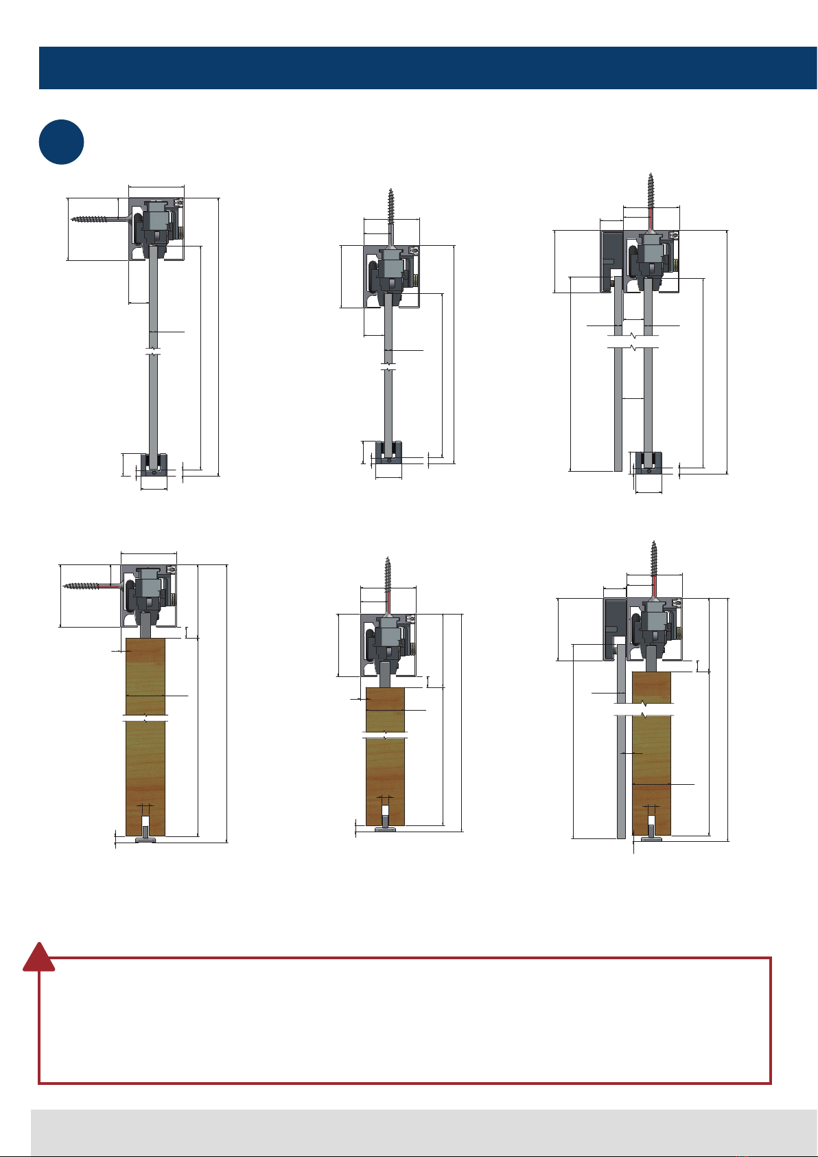
Montagemaße
installation dimensions
Wandmontage
wall mounting
Wandmontage mit Holztür
wall mounting with wooden door
Deckenmontage mit Holztür
ceiling mounting with wooden door
Deckenmontage mit Seitenteil und Holztür
ceiling mounting with side panel and
wooden door
Deckenmontage
ceiling mounting
Deckenmontage mit Seitenteil
ceiling mounting with side panel
BESONDERER HINWEIS:
Für die Auslegung der Anlage und um die korrekten
Profil,- Glas und Montagemaße zu erhalten nutzen Sie
bitte unser Planungstool oder kontaktieren Sie einen
unserer Anwendungstechniker.
SPECIAL NOTICE:
For the design of the installation and to obtain the correct
profile, glass and installation dimensions, please use our
planning tool or contact our technical department.
!
1
26
22
5,5
H
GH= H-54
55
21
61,5
20
8-12,76
9 +/-3
26
22
< 6
5,5
H
20
61,5
27
55
GH= H-54
8-12,76
21,5
61,5
22,5
55
20
26
22
H
27
9 +/-3
5,5
GH= H-54
GHF= H-46
8-12,768-12,76
H
7
5
61,5
21
55
30 - 45
>11
TH= H-78
9 +/-3
72
61,5
27
55
30 - 45
5
>11
H
TH= H-78
9 +/-3
72
7
22,5
55
27
H
72
7
61,5
30 - 45
>11
TH = H-78
GHF = H-46
9 +/-3
< 6
8-12,76

7
Montageanleitung | installation Instructions
Montagemaße
installation dimensions
Das Lochbild der Glaswand kann entsprechend dem Raster 225 mm
verschoben werden. Sollten Sie Probleme beim auslegen der Anlage
haben kontaktieren Sie unsere Anwendungstechnik.
The hole pattern of the glass wall can be shifted according to the
grid of 225 mm. If you have problems with the layout of the system,
please contact our technical department.
BESONDERER HINWEIS:
Für die Auslegung der Anlage und um die korrekten
Profil,- Glas und Montagemaße zu erhalten nutzen Sie
bitte unser Planungstool oder kontaktieren Sie einen
unserer Anwendungstechniker.
SPECIAL NOTICE:
For the design of the installation and to obtain the correct
profile, glass and installation dimensions, please use our
planning tool or contact our technical department.
!
1
3446-__-300 / 3447-__-300
3446-__-200 = 9x225
3446-__-250 = 11x225
3446-__-300 / 3447-__-300 = 13x225
3446-__-250
3446-__-200
33
161 161 6161
225225 225
40
Ø 12
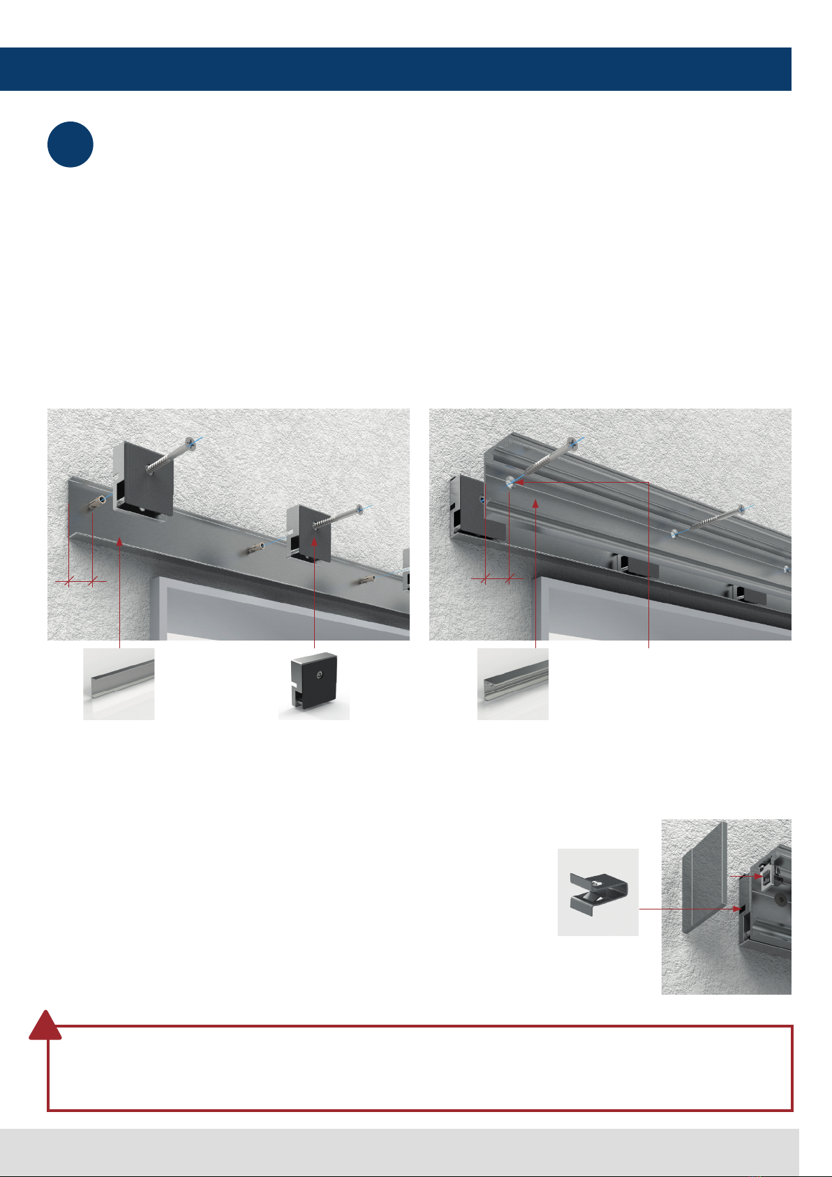
Abdeckkappenhalter montieren
install cover cap bracket
Falls Abdeckkappen verwendet werden sollen, schieben
Sie bitte auf jeder Seite eine Abdeckkappenhalterung in
das Profil und fixieren Sie diese mit der Madenschraube
ca. 1mm vom Profilende und stecken Sie die beiliegende
Klammer in die Abdeckkappenhalterung.
If cover caps are to be used, please push one cover cap
bracket into the profile on each side and fix it the profile
with the grub screw approx. 1mm from the end of the
profile and insert the enclosed clip into the cover cap
bracket.
2

8
EVERYSPACE interior
Montage Laufschiene
mounting the guide rail
Montage der Laufschiene an der Bausubstanz mit
geeignetem Montagematerial.
•Jede Bohrung verschrauben – Verletzungsgefahr
•Tragfähigkeit der Verbindung sowie der
Bausubstanz sicherstellen – Verletzungsgefahr
Richten Sie die Laufschiene aus:
Horizontal max. 2mm/1000mm, Vertikal +/-1,5mm
Mounting of the guide rail on the building structure with
suitable fastening material.
•every fanstening hole must be used - risk of injury.
•ensure load-bearing capacity of connection and
the building structure - risk of injury
Align the guide rail: Horizontal max. 2mm/1000mm,
vertical +/-1.5mm.
Bei Unebenheiten der Bausubstanz verwenden Sie unsere
Ausgleichsbleche 3440VA-AB in entsprechender Anzahl.
(Blechstärke 1 mm) Die Ausgleichsbleche sind für die
Decken und Wandmontage geeignet.
In case of unevenness of the building structure use our
3440VA-AB shims in the appropriate quantity. (sheet
thickness 1 mm) The shims are suitable for ceiling and wall
mounting.
3
ACHTUNG
Verwenden Sie ein für den Untergrund und die bauliche
Situation geeignetes Befestigungsmaterial.
ATTENTION
Use fastening material suitable for the underlying
structure.
!
Ausgleichsblech (10 Stk./Packung)
Art.-Nr.: 3441VA-AB
Shim (10 pcs./package)
art no.: 3441VA-AB
9
Montageanleitung | installation Instructions
Montage Laufschiene – optional: Zargenadapter
mounting the guide rail - optional: frame adapter
Übertragen Sie die Bohrungen der Laufschiene
(3440E_-2) auf das Abdeckprofil (3440E_ 4).
Im Randbereich muss eine zusätzliche Bohrung in die
Laufschiene eingebracht werden (28mm)
Transfer the holes of the guide rail (3440E_-2) onto the
cover profile (3440E_ 4). An additional hole must be
drilled in the edge area of the guide rail (28mm).
Übertragen Sie die Bohrungen auf die Wand und
Befestigen Sie die Laufschiene zusammen mit den
Zargenadaptern auf die Wand.
Transfer the drill holes to the wall and fasten the guide rail
together with the frame adapters to the wall.
Klammer (8820-45ST8) in die
Öffnung des Zargenadapter stecken.
Insert the clamp (8820-45ST8) into
the opening of the frame adapter.
Nach der Türinstallation mit
Abdeckkappen verschließen.
After the door installation, insert the
end caps.
3
ACHTUNG
Verwenden Sie ein für den Untergrund und die bauliche
Situation geeignetes Befestigungsmaterial.
ATTENTION
Use fastening material suitable for the underlying
structure.
!
Abdeckung hinten
Art.-Nr.: 3440E_-4
cover panel behind
art no.: 3440E_-4
Klammer
Art.-Nr.: 8820-45ST8
clamp
art no.: 8820-45ST8
Laufschiene
Art.-Nr.: 3440E_-2 / 32
guide rail
art. no.: 3440E_-2 / 32
Spezifikation Bohrung: Ø 6,5 mm
Senkung: 90° Ø 12,5 mm
specification hole: Ø 6.5 mm
Countersink: 90° Ø 12.5 mm
Zargendistanzsstück
Art.-Nr.: 3441ZN-ZA
frame spacer piece
art no.: 3441ZN-ZA
3.A
3.B
3.C
3.D
3.D
28
3.C
28
10
EVERYSPACE interior
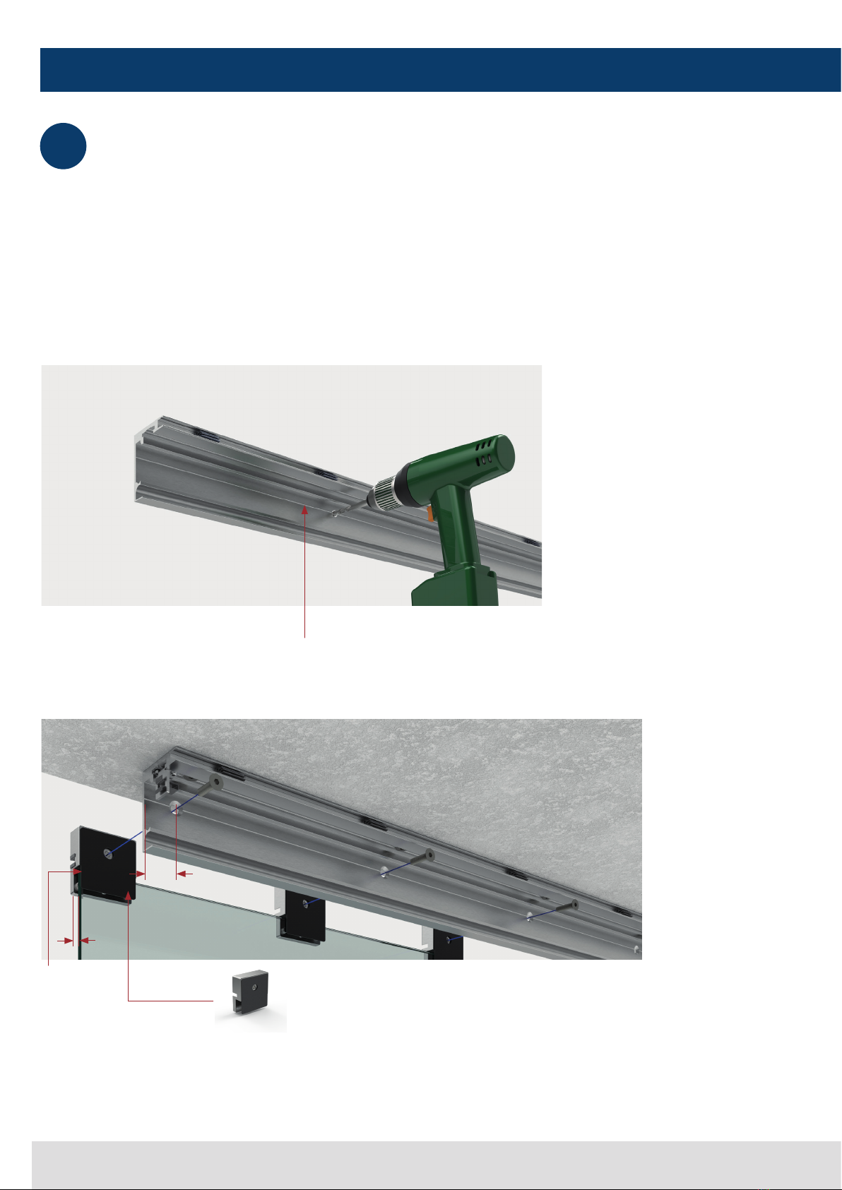
3Montage Laufschiene – optional: Montage Seitenteilhalterung
mounting the guide rail - optional: mounting the side panel bracket
Befestigen Sie je Seitenteil 3 bzw. 4 Stück 3441ZN-SM
an der Laufschiene. Bohren Sie dazu entsprechende
Löcher in die dafür vorgesehene Bohrrille. Positionierung
der Seitenteilklemmstücke: jeweils links und rechts 6 mm
am Seitenteil überstehen lassen. Die übrigen 1 bzw. 2
gleichmäßig im verbleibenden Freiraum verteilen.
Attach 3 or 4 pieces 3441ZN-SM per side panel to
the guide rail. To do this, drill the corresponding holes in
the provided drill groove. Positioning of the side panel
clamping pieces: leave 6 mm protruding from the side
panel on the left and right. Distribute the remaining 1 or 2
evenly in the remaining free space.
Spezifikation Bohrung: Ø 6,5 mm
Senkung: 90° Ø 12,5 mm
specification hole: Ø 6.5 mm
Countersink: 90° Ø 12.5 mm
Glasmontagestück
Art.-Nr.: 3441ZN-SM
glass mounting piece
art no.: 3441ZN-SM
6 mm am Seitenteil
überstehen lassen
allow 6 mm to
protrude on the side
panel
Bohrrille
drill groove
28
6
11
Montageanleitung | installation Instructions
3Montage Laufschiene – optional: Montage Seitenteilhalterung
mounting the guide rail - optional: mounting the side panel bracket
Die Blechklammer in die Seitenteilhalterung einstecken.
Insert the metal clips into the side panel holder.
Nach erfolgreicher Systemmontage Abdeckkappen
aufstecken.
After successful system installation attach the end
caps.
Das Seitenteil einschwenken und positionieren Swing in and position the side panel
3.A
3.E
3.F
3.A
Das Seitenteil mit den Klemmschrauben fixieren Secure the side panel with the clamping screws
3.B
Die beiliegenden Magnete in die Seitenteilhalterungen
einkleben.
Attach the enclosed magnets to the side panel brackets.
3.C
Blendenprofil ablängen, entfetten, Schutzfolie der
Magnete abziehen und Blendenprofil aufkleben.
Cut the cover profile to length, degrease, remove the
protective film of the self-adhesive magnets and attach to
the cover profile..
3.D
3.D 3.C
3.B
3.F
3.E

12
EVERYSPACE interior
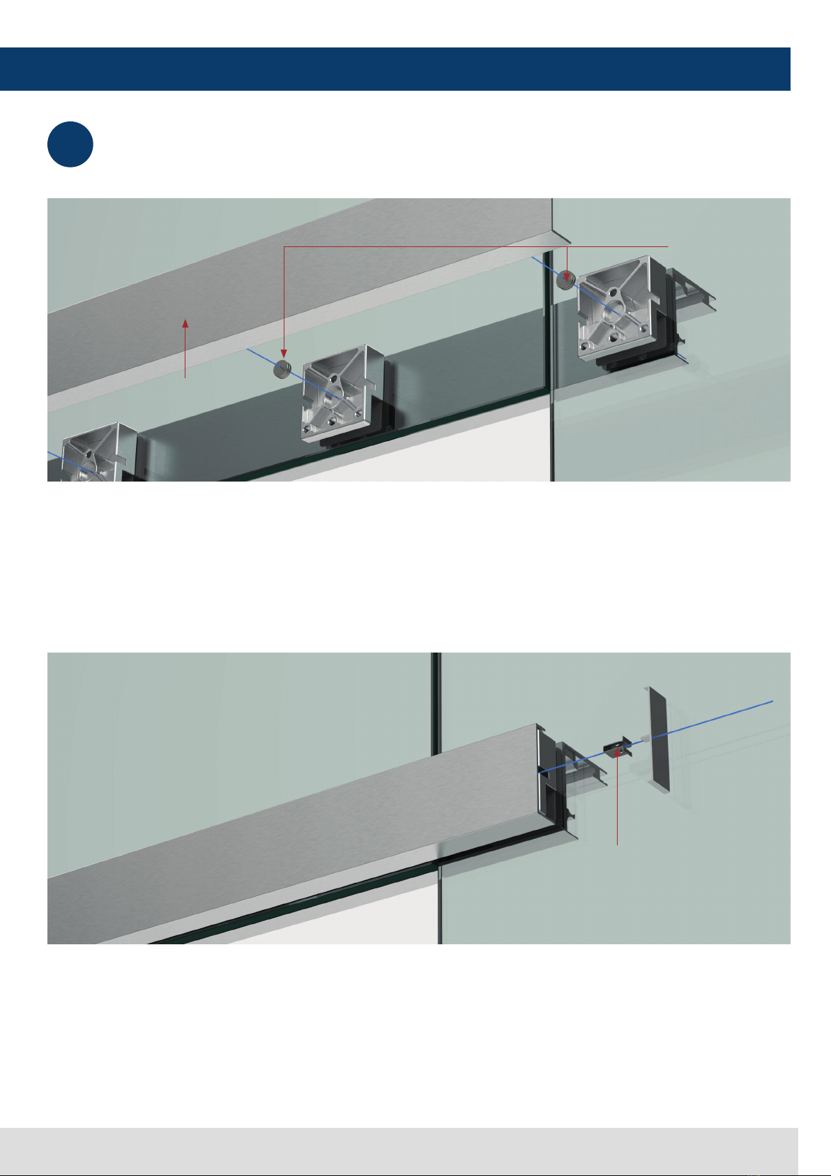
4Glasmontage
glass mounting
Hartzell
(Teil 1)
mit beiliegendem Klebepunkt auf der
Laufschiene positionieren
Attach the provided self-adhesive hartzell
(part 1)
) onto
the guide rail.
Kunststoffschlauch (Art.-Nr. Kuschl10x8x6) (Teil 2) in die
Glas-bohrung einbauen, um Glas-Metallkontakt zu vermeiden.
Insert the plastic hose (Art. No. Kuschl10x8x6) (part 2) into
the glass hole to avoid glass-to-metal contact.
Laufschiene auf Glas positionieren und mit Hilfe der
Schrauben und dem Glasmontagestück
(Teil 3)
am Glas
montieren. Anzugsdrehmoment 12Nm!
Position the guide rail on the glass and fasten it to the glass
using the screws and the glass mounting piece
(part 3)
to
the glass.. Tightening torque = 12Nm!
4.A
4.B
4.C
(Teil 1)
(Teil | part 3)
(Teil | part 2)
13
Montageanleitung | installation Instructions
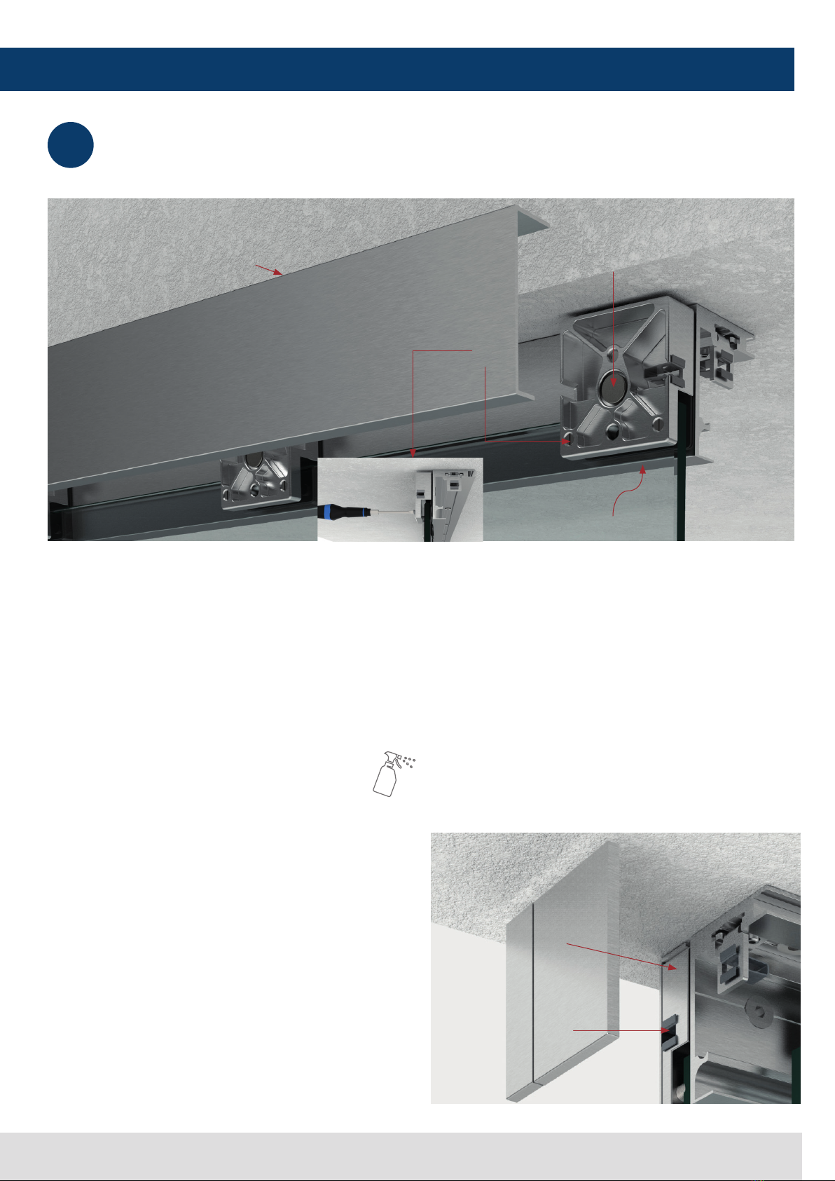
4Glasmontage
glass mounting
Die beiliegenden Magnete (Teil 3) über die Länge
gleichmäßig in die Glasmontagestücke einkleben.
Die Abdeckblende (Teil 4) innen entfetten. Dann die
Schutzfolie der Magnete abziehen und mit dem langen
Schenkel nach unten auf die Glasmontagestücke und die
Magnete fest aufdrücken.
Attach the enclosed magnets
(part 3)
into the evenly
spaced glass mounting pieces.
...degrease the inside of the cover panel
(part 4)
, peel
off the protective film of the magnets and attach them
with the long the long side down onto the glass mounting
pieces firmly.
Die Blechklammer
(Teil 5)
in die Glasmontagestücke
drücken und nach Montage der Abdeckblende die
Abdeckkappen aufstecken.
Press the metal clip
(part 5)
into the glass mounting pieces
and, after mounting the cover panel, push on the cover caps.
4.D
4.E
(Teil| part 4)
(Teil | part 3)
(Teil | part 5)

14
EVERYSPACE interior
Montage Bodenführung
mounting the floor guide
Einsetzen der Endanschläge und Aktivatoren
insertion of the end stops and activators
5
6
(Teil 1) der Bodenführung mit geeignetem Befestigungs-
material
am Fußboden befestigen.
(Teil 2)
in Richtung des blauen Pfeil auf Teil 1 schieben
und die zu verbauende Glasstärke einstellen.
Die Einstellung mit den Madenschrauben
(Teil 3)
sichern.
Fasten (part 1) of the floor guide to the floor with suitable
fastening material.
Slide (part 2) in the direction of the
blue arrow
onto part 1
and set the to the installed glass thickness.
Secure the setting with the grub screws (part 3).
Endanschlag (Teil 4) und Aktivator (Teil 5) links und rechts
in die Laufschiene eindrehen.
Den Abstand (A) zwischen Aktivator und Endanschlag
herstellen. Vorderkante Gummipuffer bis Mitte Aktivator.
50kg Laufwagen: 182mm
100kg Laufwagen: 276mm
Aktivator und Endanschlag in der Laufschiene mit den
Madenschrauben (Teil 6) fixieren.
Insert the end stop (part 4) and the activator (part 5) into
the left and right side of the guide rail.
Establish the distance (A) between activator and end stop.
Front edge of rubber buffer to center of activator.
50kg carriage: 182mm
100kg carriage: 276mm
Fasten the activator and the end stop in the guide rail with the
grub screws (part 6).
ACHTUNG
Verwenden Sie ein für den Untergrund und die bauliche
Situation geeignetes Befestigungsmaterial.
ATTENTION
Use fastening material suitable for the underlying
structure.
!
(Teil | part 1)
(Teil | part 4)
(Teil | part 5)
(Teil | part 2)
(Teil | part 3)
(Teil | part 6)
8 - 12,76
A
ca. 20

15
Montageanleitung | installation Instructions
7Optional: Montage Holzschiebetüradapter
optional: mounting wooden sliding door adapter
ACHTUNG
Verwenden Sie ein für den Untergrund und die bauliche
Situation geeignetes Befestigungsmaterial.
ATTENTION
Use fastening material suitable for the underlying
structure.
INFO:
Die Laufwagen auf 10 mm Glasstärke einstellen.
INFO
Adjust the carriages to glass thickness 10 mm..
!
Den Holztüradapter
(Teil 1)
links und rechts mittig auf der
Holzschiebetür montieren.
Mount the wooden door adapter
(part 1)
on the left and
right center of the wooden sliding door.
Klemmen Sie die Laufwagen in Verbindung mit dem
Sicherungsstift auf die Holztüradapter.
Clamp the carriages onto the wooden door adapters using
the locking pin.
Die Bodenführung
(Teil 2)
mit geeignetem
Befestigungsmaterial am Fußboden befestigen.
Fasten the floor guide
(part 2)
to the floor using suitable
fastening material.
7. A
7. B
7. C
(Teil 1)
(Teil 2)

16
EVERYSPACE interior
850kg-Laufwagen montieren
assembling 50kg roll-carriage
HINWEIS:
Es besteht die Möglichkeit einen
optionalen Sicherungsstift in
beiden Laufwagen zu verbauen.
NOTE:
As an option, it is possible to
install a safety stud in both
carriages.
!
Markierung auf der Glaseinstellkrone
Beispiel: 8 mm Glas
marking on the glass setting crown
Example: 8 mm glass
Den Laufwagen öffnen.
Open the roll-carriage.
Die Glaseinstellkronen entsprechend der Glasdicke
positionieren. Es können vier verschiedene Glasstärken
gewählt werden: 8 mm | 8,76 mm | 10 mm | 10,76 mm
Position the glass adjustment crowns according to the glass
thickness. Four different glass thicknesses can be selected:
8 mm | 8.76 mm | 10 mm | 10.76 mm
7. A
7. B
Ø 8
8

17
Montageanleitung | installation Instructions
8100kg-Laufwagen montieren
assembling 100kg roll-carriage
Laufwagen öffnen
8.B
Die Glaseinstellkronen entsprechend der Glasdicke
positionieren
Open the roll-carriage
8.B
Position the glass adjustment crowns according to the
glass thickness
Markierung auf 12 Uhr Stellung 8 mm
mark at 12 o›clock position 8 mm
Markierung auf 1 Uhr Stellung 8,76 mm
mark at 1 o›clock position 8.76 mm
Markierung auf 2 Uhr Stellung 10 mm
mark at 2 o›clock position 10 mm
Markierung auf 3 Uhr Stellung 10,76 mm
mark at 3 o›clock position 10,76 mm
Markierung auf 2 Uhr + Distanzring
(Teil 1)
12 mm
mark at 2 o›clock + spacer ring
(part 1)
12mm
Markierung auf 3 Uhr + Distanzring
(Teil 1)
12,76 mm
mark at 3 o›clock + spacer ring
(part 1)
12.76 mm
8.A 8.A
(Teil | part 1)
(Teil | part 1)
18
EVERYSPACE interior
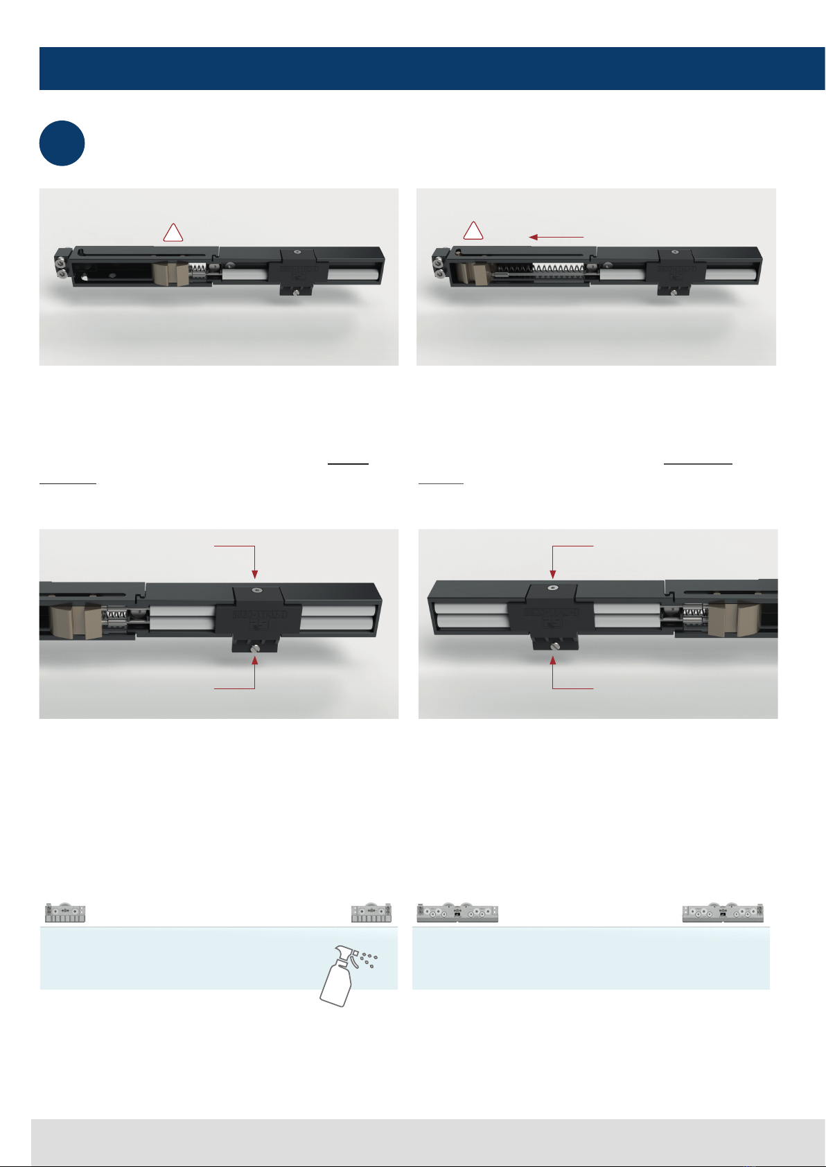
Feder entspannt
spring is unloaded
Feder gespannt
spring is loaded
Bei Verwendung des einseitigen Softstopp (Art-Nr.:
3441RAL7016-SSD50/100), muss dieser durch drehen
der Kunststoffkappe
(Teil 1)
an die linke und rechte Seite
angepasst werden. Somit zeigen die Zapfen
(Teil 2)
für
die Glasführung immer nach unten.
When using the one-sided Softstopp (Art. no.:
3441RAL7016-SSD50/100), it must be adjusted by
turning the plastic cap
(part 1)
to the left and right, so
that the pins
(part 2)
for the glass guidance always point
downwards.
Den Softstopp vorbereiten: Die Mitnehmergabel in
Pfeilrichtung schieben und damit die Federn spannen.
Beim Einbau des Softstopp müssen die Federn immer
gespannt sein.
Prepare the Softstopp: Push the driving fork in the direction
of the arrow and thereby tensioning the springs. When
installing the Softstopp, the springs must always be
loaded.
Glas im Klemmbereich reinigen und Laufwagen auf die
Glaskante klemmen.
Clean the glass in the clamping area and clamp the roller
unit onto the edge of the glass.
9.A
9.B
!
!
9Laufwagen / Softstopp montieren
roll-carriage / mounting the Softstopp
(Teil | part 1)
(Teil | part 2)
(Teil | part 1)
(Teil | part 2)

19
Montageanleitung | installation Instructions
9Laufwagen / Softstopp montieren
roll-carriage / mounting the Softstopp
9.C
9.D
Nullstellung
zero setting
Nullstellung
zero setting
! !
!
25Nm 14Nm
25Nm
Rolle auf Nullstellung (höchste Stufe) bringen Set the roller to the neutral position (highest level)
Softstopp an den Laufwagen montieren. Mount the Softstopp onto the roll-carriage
niedrigste Stufe der Laufrolle
lowest level of the rollers
höchste Stufe der Laufrolle
highest level of the rollers

20
EVERYSPACE interior
10 Tür einhängen
attaching the door
Die Laufschiene und die Laufrollen vor dem
einhängen der Tür reinigen und einhängen.
Clean and mount the guide rail and the rollers
before attaching the door
Ausrichten der Tür:
aligning the door:
10.A
10.B
Nach der Einstellung sichern!
Secure after setting!
Exzenter +/-3mm
eccenter +/-3mm
HINWEIS:
Die Einstellung nach der Ausrichtung halten und direkt sichern um ein
Absacken der Tür zu vermeiden. Achten Sie auf ausreichend Bodenfreiheit
bei eventuell schief zulaufenden Böden.
NOTE:
Hold the adjustment after alignment and secure it directly to avoid the door
from sagging. Ensure sufficient ground clearance in case of sloping floors.
!
Table of contents


