manuals.online logo
Brands
  1. Home
  2. •
  3. Brands
  4. •
  5. Niko
  6. •
  7. Security Sensor
  8. •
  9. Niko Swiss Garde 360 Presence DALI Secondary... User manual

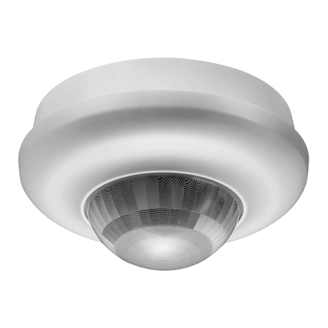
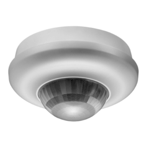
Niko Swiss Garde 360 Presence DALI Secondary... User manual

HØ Ø
2,0m 2,0m 16m
2,5m 3,5m 20m
3,0m 6,0m 24m
3,5m 6,0m 24m
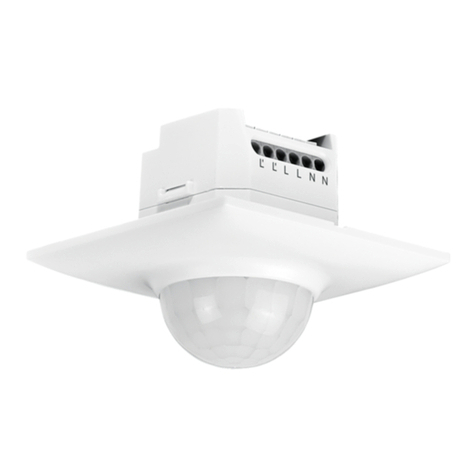
Secondary presence detector 24 m, 360°
Sekundär-Präsenzmelder 24m, 360°
Détecteur de présence secondaire 24m, 360°
4
6
DE
EN
FR
Swiss Garde 360 Presence
DALI Secondary A-Comfort 24 m
Edition 11-2021
Art.-Nr. 41752, 41753
2
5
Ø
Ø
360°
ca. 50%
100%
Ø
H
>1m
❄
❆
✗
✗
✗
✗
✗
✗
✗
❄
✗
✗
✗
✗
✗
✗
✗
❄❄
✗
✗
✗
✗
✗
✗
✗
❄
❆
x
z
✗
✗
✗
✗
✗
✗
✗
✗
✗
✗
✗
✗
✗
✗
✗
Ø
Ø
360°
ca. 50%
100%
3
Edition AP
Edition AP
Edition UP
Edition UP
L2
L1
DA+
N
DA-
T3T4
T1+2 L’LNN LL DA1 DA2DA- DA+ DA1 DA2
Master Secondary
45,9 mm 18,2 mm
117,3mm
46,4 mm 90 mm
100mm
P-IR Fernbedienung
DALI adressierbar
Art.-Nr. 41934
1
Rilevatore di presenza secondario 24m, 360°
Czujnik obecności drugorzędny o zasięgu 24m, 360 °
IT
PL
EN INSTALLATION INSTRUCTIONS
1. Product description (1)
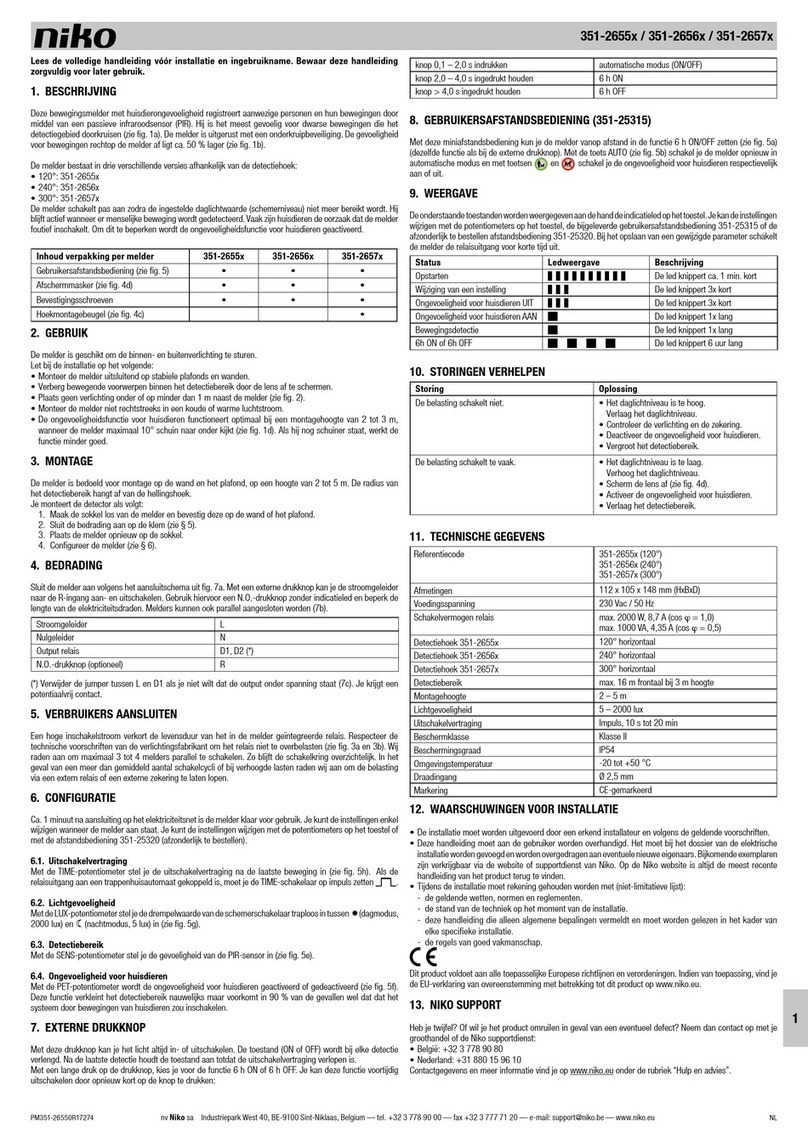
The device detects the movements and the presence of persons using a passive infrared sensor (PIR).
It reacts most sensitively to movements which are tangential to the monitored area.
Movements directly towards the detector have a reduced sensitivity of approx. -50%.
2. Application (2)
The detector is used to increase the detection range of a Master detector
(Swiss Garde 360 DALI Master A-Comfort).
The detector is designed for ceiling installation.
Adhere to the following during installation:
– Install only on stable ceilings.
– Mask moving objects in the monitored area by deactivation of the sector
(setting over remote control analogous to Master).
– Do not place any lamps underneath or next to the detector at a distance of less than 1 m away.
– Do not install in direct cold or hot air flows.
Range (1)
The recommended installation height for this detector is 2–3,5m, 2,5 is the optimal installation height.
To reduce the detection area the enclosed half-shells can be clamped between lens and cover.
It is possible to connect up to 10 secondary detectors to one Master which controls the load according to
its settings. To achieve complete converage by using several detectors, it is recommended to have
an overlap of approximately 30%.
3. Safety notes
!
Ensure that the electrical lines are de-energised before installation.
Installation is only permitted by electricians in compliance with local legislation.
4. Installation (3)
The detector is intended for ceilling installation at a height of 2 to 3,5 m.
The diameter Ø of the monitored area depends on the installed height.
Install the detector as follows:
– Remove the front cover by turning it anti-clockwise, then unscrew the upper section of the detector.
– Mark and drill the drilled holes in the desired installation location.
– Pull the cable through the cable ducts.
– Fasten the detector with a set of screws/dowels.
– Wire the detector according to item 5.
– Fit and screw back on the upper section of the detector.
– Fasten the front cover by turning it clockwise.
– The detector is after about 40s operational and is automatically detected by master.
5. Technical Data
Supply voltage Via DALI Bus
Power consumption 5.5mA
Detection angle 360°
Detection range max. Ø6 m presence, approx. Ø24 m at a height
of 3m
Installation height 2–3.5m
Protection class IP54
Temperature range -5 to +50°C
Dimensions Edition UP: Ø100x46.4 mm (visible dimensions)
Edition AP: Ø117.3x45.9mm (visible dimensions)
Drill-hole (Edition UP) Ø90mm
Colour RAL9010
6. Sensitivity setup, factory reset and test mode
Programming and configuration are done via the P-IR remote control DALI addressable Art.-Nr. 41934 (6).
The programming mode will indicated by the yellow LED. Each receiving of a proper signal is confirmed
with a short lapse of the yellow LED.
Note: At the secondary detectors allways, the yellow led flash as a response to a pressing
of the «Lock/Unlock» or «Status» button ( the master always response with the green LED).
Setting of sensitivity (1)
The 360° detection range is split into 3 sectors A – B – C of 120° each. Sensitivity may be adjusted
either for all three sectors or for each individual sector. Sectors may be completely deactivated.
Sensitivity setup for all 3 sectors:
1. Briefly press «Lock/Unlock» button: Programming mode
2. Briefly press «Sens.» button: sensitivity for all 3 sectors
3. Set sensitivity by pressing «1» for Max, «2» for High, «3» for Low, «4» for Min
4. Briefly press «Lock/Unlock» button: Operating mode
Example: The detector needs to work with Low sensitivity. Press the «Lock/Unlock» button; the yellow LED switches
on. Then press «Sens.» and «3». Finally, press «Lock/Unlock» again; the yellow LED switches off.
Sensitivity setup for an individual sector sample:
1. Briefly press «Lock/Unlock» button: Programming mode
2. Long press «Sens.» button >4 s: sensitivity for individual sector
3. Select by repeatedly pressing «Next» button: red LED for sector A, blue LED for sector B, green LED for sector C
4. Set sensitivity by pressing «1» for Max, «2» for High, «3» for Low, «4» for Min
5. Briefly press «Lock/Unlock» button: Operating mode
Individual sectors may be deactivated with «Test On/Off» button(enabled 1x flash, disabled 2x flash).
It is recommended to check the sensitivity in test mode after configuration. Each sector is thus indicated
by its respective LED colour code. The LED remains off in case of deactivated sectors.
To check settings, press «Status» followed by «Sens.» to display sensitivity.
The presence detector displays the sensitivity by the respective number of LED flashes.
Example: Press «Status» button and then «Sens.». The yellow LED flashes 3 times,
which means that a Low sensitivity has been set.
Reset to default settings
If the detector needs to be reset to its default settings (Max sensitivity), meaning into the «Out-of-the-box» setup
mode, please proceed as follows:
1. Press «Lock/Unlock» button: Programming mode
2. Press and hold «Fact. set.» button for about 4s until the yellow LED switches off 2 times as confirmation.
3. Press «Lock/Unlock» button: Operating mode
Test Mode
To check, whether the detector covers the required range, it is necessary to activate
the test function at the master («Lock/Unlock» dann «Test On/Off»).
All secondary detectors connected to the dali bus are then automatically in the test. Sectors detecting
motion are identified by their respective LED colour flashing. For deactivation of the test
for the secondary detector, press «Lock/Unlock» on the secondary device.
To disable the test at all devices, press «Lock/Unlock» on the master device.“
DE INSTALLATIONSANLEITUNG
1. Produktbeschreibung (1)
Der Melder erkennt Personenbewegungen und Personenanwesenheit mittels Passiv-Infrarot Sensor (PIR).
Er reagiert am empfindlichsten bei Bewegungen, die tangential zum überwachten Bereich verlaufen.
Bewegungen welche direkt auf den Melder zu erfolgen, haben eine reduzierte Empfindlichkeit von ca. -50%.
2. Anwendung (2)
Der Melder dient zur Erweiterung des Erfassungsbereichs eines Master Melders
(Swiss Garde 360 DALI Master A-Comfort).
Der Melder ist für die Deckenmontage vorgesehen.
Bei der Installation beachten:
– Nur an stabilen Decken montieren.
– Bewegliche Gegenstände im überwachten Bereich durch deaktivieren des Sektors ausblenden
(Einstellung über Fernbedienung analog zu Master).
– Keine Leuchten unterhalb oder weniger als 1m neben dem Melder platzieren.
– Nicht in direkten Kälte- oder Wärmeluftstrom montieren.
Reichweite (1)
Die empfohlene Montagehöhe für diesen Melder ist 2–3,5m. 2,5m ist die optimale Montagehöhe.
Zur Bereichsreduktion können die beiliegenden Halbschalen zwischen Linse und Abdeckung geklemmt werden.
Es ist möglich, 10 Sekundär-Melder an einen Master anzuschliessen, der die Beleuchtung gemäss seinen
Einstellungen steuert. Um beim Einsatz mehrerer Melder eine komplette Deckung zu erreichen,
empfiehlt es sich, mit einer Überlappung von ca. 30% zu rechnen.
3. Sicherheitshinweise
!
Vor der Installation prüfen, dass die elektrischen Leitungen spannungsfrei sind.
Die Installation darf nur durch Elektrofachpersonal unter Einhaltung der landesüblichen
Vorschriften erfolgen.
4. Montage (3)
Der Melder ist für eine Deckenmontage von 2 bis 3,5m Höhe vorgesehen.
Der Durchmesser Ø des überwachten Bereichs ist abhängig von der Montagehöhe.
Zur Montage:
– Frontabdeckung mittels Drehung im Gegenuhrzeigersinn entfernen, danach Melder Oberteil entfernen.
– Bohrlöcher am gewünschten Montageort anzeichnen und bohren.
– Leitung durch Kabeldurchführungen ziehen.
– Melder mit Schrauben/ Dübel Set befestigen.
– Melder gemäss Punkt 5. verdrahten.
– Melder Oberteil anbringen.
– Frontabdeckung mittels Drehung im Uhrzeigersinn befestigen.
– Der Melder ist nach ca. 40s betriebsbereit und wird vom Master automatisch erkannt.
5. Technische Daten
Nennspannung Via DALI Bus
Stromverbrauch 5,5mA
Erfassungsbereich 360°
Reichweite Max. Ø 6m Präsenz, ca. Ø 24m bei 3m Höhe
Montagehöhe 2–3,5m
Schutzart IP54
Temperaturbereich -5 bis +50°C
Masse Edition UP: Ø100x46,4 mm (Sichtmass)
Edition AP: Ø117,3x45,9mm (Sichtmass)
Bohrung (Edition UP) Ø90mm
Farbe RAL9010
6. Einstellung der Empfindlickeit, Rückstellung und Gehtest
Die Programmierung ist über die P-IR Fernbedienung DALI adressierbar Art.-Nr. 41934 möglich (6).
Im Programmiermodus leuchtet die gelbe LED und jeder Empfang eines korrekten Signals wird
mit einem kurzen Erlöschen der gelben LED bestätigt.
Hinweis: Bei den Sekundär-Meldern leuchtet immer die gelbe LED als Antwort auf ein Drücken
der «Lock/Unlock» oder «Status» Taste (beim Master immer die grüne LED).
Einstellung der Empfindlichkeit (1)
Der Erfassungsbereich von total 360° ist in 3 Sektoren, A – B – C, von jeweils 120° aufgeteilt.
Die Empfindlichkeit kann entweder für alle Sektoren gemeinsam oder für jeden Sektor einzeln
eingestellt werden. Ein Sektor kann vollständig ausgeschaltet werden.
Einstellen der Empfindlichkeit für alle Sektoren gleichzeitig:
1. Taste «Lock/Unlock» kurz drücken: Programmiermodus
2. Taste «Sens.» kurz drücken: Empfindlichkeit für alle Sektoren gleichzeitig
3. Setze Empfindlichkeit mit «1» für Max, «2» für High, «3» für Low, «4» für Min
4. Taste «Lock/Unlock» kurz drücken: Betriebsmodus
Beispiel: Der Melder soll mit Low Empfindlichkeit arbeiten. Die Taste «Lock/Unlock» drücken,
die gelbe LED schaltet sich ein. Dann «Sens.» und «3» drücken.Abschliessend erneut «Lock/Unlock»
drücken, die gelbe LED schaltet sich aus.
Einstellen der Empfindlichkeit für einen einzelnen Sektor:
1. Taste «Lock/Unlock» kurz drücken: Programmiermodus
2. Taste «Sens.» lang drücken >4s: Empfindlichkeit für einzelne Sektoren
3. Wähle mit wiederholt «Next» drücken: rote LED für Sektor A, blaue LED für Sektor B, grüne LED für Sektor C
4. Setze Empfindlichkeit mit «1» für Max, «2» für High, «3» für Low, «4» für Min
5. Taste «Lock/Unlock» kurz drücken: Betriebsmodus
Mit der «Test On/Off» kann ein einzelner Sektor deaktiviert werden (aktiv 1x blinken, inaktiv 2x blinken). Nach der
Konfiguration der Sektoren wird empfohlen die Empfindlichkeit im Geh-Test zu überprüfen. Dabei wird jeder Sektor
mit der jeweiligen LED Farbe angezeigt. Bei deaktiviertem Sektor bleibt die LED ausgeschaltet.
Zur Anzeige der programmierten Empfindlichkeit erst «Status» und dann «Sens.» drücken.
Der Melder zeigt die Empfindlichkeit durch eine entsprechende Anzahl von Blinksignalen der LED an.
Beispiel: Die Taste «Status» und dann «Sens.» drücken. Die gelbe LED
blinkt dreimal, was bedeutet, dass eine Low Empfindlichkeit eingestellt ist.
Rückstellung auf Werkseinstellungen
Soll der Melder auf seine Werkseinstellung (Max Empfindlichkeit) zurückgesetzt werden,
wie in «Out-of-the-box», bitte wie folgt vorgehen:
1. Taste «Lock/Unlock» drücken: Programmiermodus
2. Taste «Fact. set.» ca. 4s gedrückt halten, bis sich die gelbe LED zur Bestätigung zweimal kurz ausschaltet.
3. Taste «Lock/Unlock» drücken: Betriebsmodus
Gehtest
Um zu prüfen, ob der Melder den benötigten Bereich erfasst, müssen sie die Testfunktion
beim Master aktivieren («Lock/Unlock» dann «Test On/Off»).
Alle am DALI-Bus angeschlossenen Sekundär-Melder befinden sich dann automatisch im Test.
Je nach Erfassungs-Sektor leuchtet die entsprechende LED auf bei Detektion.
Zur Deaktivierung des Tests für den Sekundär-Melder drücken sie beim Sekundär-Melder auf «Lock/Unlock».
Um den Test bei allen Meldern zu deaktivieren drücken sie beim Master auf «Lock/Unlock».
Edition AP
Edition UP
HØ Ø
2,0m 2,0m 16m
2,5m 3,5m 20m
3,0m 6,0m 24m
3,5m 6,0m 24m
Secondary presence detector 24 m, 360°
Sekundär-Präsenzmelder 24m, 360°
Détecteur de présence secondaire 24m, 360°
4
6
DE
EN
FR
Swiss Garde 360 Presence
DALI Secondary A-Comfort 24 m
Edition 11-2021
Art.-Nr. 41752, 41753
2
5
Ø
Ø
360°
ca. 50%
100%
Ø
H
>1m
❄
❆
✗
✗
✗
✗
✗
✗
✗
❄
✗
✗
✗
✗
✗
✗
✗
❄❄
✗
✗
✗
✗
✗
✗
✗
❄
❆
x
z
✗
✗
✗
✗
✗
✗
✗
✗
✗
✗
✗
✗
✗
✗
✗
Ø
Ø
360°
ca. 50%
100%
3
Edition AP
Edition AP
Edition UP
Edition UP
L2
L1
DA+
N
DA-
T3T4
T1+2 L’LNN LL DA1 DA2DA- DA+ DA1 DA2
Master Secondary
45,9 mm 18,2 mm
117,3mm
46,4 mm 90 mm
100mm
P-IR Fernbedienung
DALI adressierbar
Art.-Nr. 41934
1
Rilevatore di presenza secondario 24m, 360°
Czujnik obecności drugorzędny o zasięgu 24m, 360 °
IT
PL
FR NOTICE D’INSTALLATION
1.Description du produit (1)
Le détecteur détecte les mouvements et la présence de personnes par un capteur infrarouge passif (PIR).
Il réagit le plus sensiblement aux mouvements tangentiels par rapport à la zone surveillée.
Les mouvements qui sont directement sur le détecteur ont une sensibilité réduite d’env. -50%.
2. Utilisation (2)
Le détecteur est utilisé pour augmenter la portée de détection d’un détecteur Master
(Swiss Garde 360 DALI Master A-Comfort).
Le détecteur est prévu pour un montage au plafond.
Tenir compte des points suivants lors de l’installation :
– Ne monter que sur des plafonds stables.
– Masquer les objets qui bougent dans la zone surveillée avec désactivation du secteur
(Réglage sur la télécommande analogue à maîtriser).
– Ne pas mettre d’appareils d’éclairage sous le détecteur ou à moins d’un mètre à côté du détecteur.
– Ne pas monter directement dans les courants d’air froids ni chauds.
Zone de détection (1)
La hauteur de montage recommandée pour ce détecteur est de 2 à 3,5m. La hauteur optimale étant
de 2,5m, le détecteur a alors une portée de Ø 20m au sol et de Ø 13,5m à une hauteur de table de 80 cm.
Pour réduire la zone de détection installe l‘ obturateur entre le lentille et des couvre-objectif.
Il est possible de raccorder 10 détecteurs secondaires à un élément maître, lequel commandera l’éclairage
en fonction de son paramétrage. Afin d’obtenir une couverture complète par plusieurs détecteurs,
il est recommandé de prévoir un chevauchement d’environ 30%.
3. Consignes de sécurité
!
Avant l’installation, vérifier la mise hors tension des câbles.
L’installation doit exclusivement être effectuée par des électriciens
spécialisés dans le respect des normes nationales.
4. Installation (3)
Le détecteur est prévu pour un montage au plafond de 2 à 3,5m de hauteur.
Le diamètre Ø de la zone surveillée dépend de la hauteur de montage.
Pour le montage :
– Enlever le cache avant en le tournant dans le sens inverse des aiguilles d’une montre,
ensuite dévisser la partie supérieure du détecteur.
– Tracer et percer les trous à l’endroit souhaité du montage
– Faire passer le câble par les passe-câbles.
– Fixer le détecteur avec le kit de vis/et de chevilles.
– Câbler le détecteur suivant le paragraphe 5.
– Mettre en place la partie supérieure du détecteur et la visser.
– Fixer le cache avant en le tournant dans le sens des aiguilles d’une montre.
– Le détecteur est après ca. 40s de fonctionnement et est automatiquement détecté par le master.
5. Caractéristiques techniques
Tension nominale Via bus DALI
Consommation 5,5mA
Angle de détection 360°
Portée max. Ø6 m présence, env. Ø24 m pour une
hauteur de 3m
Hauteur de montage 2–3,5m
Protection IP54
Température -5 à +50°C
Dimensions Edition UP: Ø100x46,4 mm (partie visible)
Edition AP: Ø117,3x45,9mm (partie visible)
Perçage (Edition UP) Ø90 mm
Couleur RAL9010
6. Réglage de la sensibilité, RESET et mode Test
Les réglages sont effectués via la télécommande de programmation DALI adressable Art.-Nr. 41934 (6).
Le mode programmation est indiqué sur le détecteur par le voyant LED jaune et chaque ordre correct
reçu sera indiqué par une brève extinction de ce voyant.
Remarque: sur le détecteur secondaire c’est toujours le voyant jaune qui indique une action sur
les touches «Lock/Unlock» ou «Status», au contraire du maître où c’est l voyant vert.
Réglage de la sensibilité (1)
La zone de détection de 360° est divisée en 3 secteurs, A – B – C, de chacun 120°.
La sensibilité peut être réglée uniformément en une fois pour tous les secteurs ou
de façon individuelle pour chaque secteur. Un secteur peut être désactivé.
Fixation d’une sensibilité uniforme sur tous les secteurs:
1. Appuyer sur «Lock/Unlock», mode programmation
2. Appuyer brièvement sur «Sens.», sensibilité uniforme sur tous les secteurs
3. Régler la sensibilité avec «1» pour Maximum, «2» pour Haute, «3» pour Basse, «4» pour Minimum
4. Terminer en appuyant sur «Lock/Unlock»
Exemple : La sensibilité basse est souhaitée. Appuyer sur «Lock/Unlock», la LED jaune s’allume, appuyer
brièvement sur «Sens.» puis sur «3». Terminer en appuyant sur «Lock/Unlock», la LED jaune s’éteint.
Fixation de la sensibilité d’un seul secteur:
1. Appuyer sur «Lock/Unlock», mode programmation
2. Appuyer plus de 4 s sur «Sens.», sensibilité d’un seul secteur
3. Choisir le secteur avec «Next» répété : LED rouge pour secteur A,
LED bleue pour secteur B, LED verte pour secteur C
4. Régler la sensibilité avec un appui sur «1» pour Max, «2» pour Haute, «3» pour Basse, «4» pour min
5. Terminer en appuyant sur «Lock/Unlock»
La touche «Test On/Off» permet la désactivation d’un secteur (activé 1x flash, désactivé 2x flash). Après la
configuration des secteurs, il est conseillé de contrôler la sensibilité en mode Test. Lors du test, chaque secteur actif
est indiqué par le voyant de couleur. Dans le cas d’un secteur désactivé, le voyant reste éteint.
Pour vérifier le réglage de sensibilité, appuyer sur «Status» puis «Sens». La valeur est indiquée par le nombre de
clignotement respectif du voyant vert.
Exemple : appuyer sur «Status» puis «Sens». Le voyant jaune clignote 3 fois, la sensibilité est donc sur Basse.
RESET/Réinitialisation au paramétrage d’usine
Si le détecteur doit être réinitialisé aux réglages d’usine (sensibilité max), c’est-à-dire les réglages du mode «prêt à
l’emploi», il convient de procéder comme suit:
1. Appuyer sur «Lock/Unlock», mode programmation
2. Appuyer plus de 4 s sur «Fact.set.» jusqu’à ce que la LED jaune s’éteigne brièvement deux fois pour confirmer.
3. Terminer en appuyant sur «Lock/Unlock».
Mode Test
Pour vérifier si le détecteur couvre bien la zone souhaitée, il suffit d’activer le mode test sur le détecteur maître
(appuyer sur «Lock/Unlock», puis «Test On/Off»). Tous les détecteurs secondaires raccordés au bus DALI sont alors
automatiquement en mode test. Lors d’une détection, le secteur activé est identifié par le voyant de couleur associé.
Pour sortir un détecteur secondaire du mode test, appuyer brièvement sur «Lock/Unlock» dans sa direction.
Pour sortir tous les détecteurs présents du mode test en une seule fois, appuyer brièvement sur «Lock/Unlock» en
direction du détecteur maître.»
IT ISTRUZIONI PER L’INSTALLAZIONE
1. Descrizione del prodotto (1)
Il rilevatore riconosce movimenti e presenza di persone mediante sensore a infrarossi passivo (PIR - acronimo di
Passive InfraRed).
La maggiore sensibilità si ha in presenza di movimenti che avvengono tangenzialmente all’area monitorata.
La sensibilità per movimenti che avvengono direttamente sul rilevatore è ridotta di ca. -50%.
2. Applicazione (2)
Il rilevatore serve per ampliare il raggio di azione di un rilevatore Master
(Swiss Garde 360 DALI Master A-Comfort).
Il rilevatore è previsto per il montaggio a soffitto.
All’installazione rispettare quanto segue:
– Montare solo su coperture stabili
– Occultare oggetti mobili presenti nell’area monitorata disattivando il settore
(impostazione tramite telecomando analogamente a Master).
– Non collocare alcuna lampada al di sotto o a una distanza inferiore a 1 m accanto al rilevatore.
– Non effettuare il montaggio nel flusso diretto d’aria fredda o d’aria calda.
Campo di rilevazione (1)
L’altezza di montaggio raccomandata per questo rilevatore è di 4-8 m. 6 m è l’altezza di montaggio ideale.
Per la riduzione di area è possibile fissare tra la lente e il rivestimento i gusci semicircolari in dotazione.
È possibile collegare 10 rilevatori secondari a un Master, che regola l’illuminazione in base alle proprie
impostazioni. Per raggiungere una copertura completa utilizzando più rilevatori,
si raccomanda di tenere conto di una sovrapposizione di ca. il 30%.
3. Indicazioni di sicurezza
!
Verificare che non ci sia tensione nei cavi elettrici prima dell’installazione.
L’installazione è consentita solo ad elettricisti specializzati nel rispetto delle comuni disposizioni
nazionali.
4. Montaggio (3)
Il rilevatore è previsto per montaggio a soffitto, ad altezze comprese tra 4 e 8 m.
Il diametro Ø dell’area monitorata dipende dall’altezza di montaggio.
Per il montaggio:
– Rimuovere la copertura frontale ruotandola in senso antiorario, quindi rimuovere la parte superiore del rilevatore.
– Marcare i fori da eseguire nel punto di montaggio desiderato, quindi forare.
– Far passare la linea nei passacavo.
– Fissare il rilevatore con il set viti/spine.
– Effettuare il cablaggio del rilevatore come indicato al punto 5.
– Applicare la parte superiore del rilevatore.
– Fissare la copertura frontale ruotandola in senso orario.
– Il rilevatore è pronto per il funzionamento dopo ca. 40 s e viene riconosciuto automaticamente dal Master.
5. Dati tecnici
Tensione nominale Via bus DALI
Consumo di corrente 5,5 mA
Raggio di azione 360°
Campo di rilevazione ca. Ø 24m a 6 m di altezza
Altezza di montaggio 4–8m
Tipo di protezione IP54
Range di temperatura da -5 a +50°C
Dimensioni Edition UP: Ø100x46,4 mm (parte visibile)
Edition AP: Ø117,3x45,9mm (parte visibile)
Foro (Edition UP) Ø90mm
Colore RAL9010
6. Impostazione della sensibilità, ripristino e walk test
La programmazione si effettua dal telecomando P-IR d’indirizzamento DALI n° art. 41934 (6).
Nella modalità di programmazione si accende il LED giallo e la ricezione di un segnale corretto viene
confermata con un breve spegnimento del LED giallo.
Nota: Nei rilevatori secondari il LED giallo si accende sempre in risposta a una pressione
del tasto «Lock/Unlock» o «Status» (nel Master si accende sempre il LED verde).
Impostazione della sensibilità (1)
Il raggio di azione di 360° è suddiviso nei 3 settori A – B – C di 120° ciascuno.
È possibile impostare contemporaneamente la sensibilità per tutti i settori oppure singolarmente per ciascun settore.
Un settore può essere completamente disattivato.
Impostazione contemporanea della sensibilità di tutti i settori:
1. Premere brevemente il tasto «Lock/Unlock»: Modalità di programmazione
2. Premere brevemente il tasto «Sens.»: Sensibilità per tutti i settori contemporaneamente
3. Impostare la sensibilità su «1» per max., «2» per high, «3» per low, «4» per min.
4. Premere brevemente il tasto «Lock/Unlock»: Modalità d’esercizio
Esempio: Il rilevatore deve operare alla sensibilità low. Premere il tasto «Lock/Unlock»;
il LED giallo si attiva. Dopo di ciò premere «Sens.», quindi «3». Ripremere infine il tasto «Lock/Unlock»;
il LED giallo si disattiva.
Impostazione della sensibilità per un singolo settore:
1. Premere brevemente il tasto «Lock/Unlock»: Modalità di programmazione
2. Premere a lungo il tasto «Sens.» >4s: Sensibilità per singoli settori
3. Premendo ripetutamente «Next» selezionare: LED rosso per il settore A, LED blu per il settore B, LED verde per
il settore C
4. Impostare la sensibilità su «1» per max., «2» per high, «3» per low, «4» per min.
5. Premere brevemente il tasto «Lock/Unlock»: Modalità d’esercizio
Con «Test On/Off» è possibile disattivare un singolo settore (attivo 1 lampeggiamento, inattivo 2 lampeggiamenti).
Dopo la configurazione dei settori si consiglia di verificare la sensibilità con il walk tet. Ogni settore viene segnalato
con il corrispondente colore del LED. Per il settore disattivato il LED rimane spento.
Per l’indicazione della sensibilità programmata premere prima «Status» e poi «Sens».
Il rilevatore visualizza la sensibilità con un relativo numero di lampeggiamenti del LED.
Esempio: Premere il tasto «Status», quindi «Sens». Il LED giallo
lampeggia tre volte; ciò significa che è impostata una sensibilità bassa.
Ripristino delle impostazioni di fabbrica
Se il rilevatore deve essere ripristinato alle rispettive impostazioni di fabbrica (sensibilità massima),
come in «Out-of-the-box», procedere come segue:
1. Premere il tasto «Lock/Unlock»: Modalità di programmazione
2. Tenere premuto per ca. 4 secondi il tasto «Fact. set» fino a quando il LED giallo si disattiva due volte a conferma.
3. Premere il tasto «Lock/Unlock»: Modalità d’esercizio
Walk test
Per verificare se il rilevatore rileva l’area richiesta, è necessario attivare
nel Master una funzione Test («Lock/Unlock» successivamente «Test On/Off»).
Tutti i rilevatori secondari collegati al bus DALI si trovano così automaticamente nella modalità Test.
A seconda del settore di azione si illumina il relativo LED in caso di rilevamento.
Per la disattivazione del Test per il rilevatore secondario nel rilevatore secondario premere su «Lock/Unlock».
Per disattivare il test in tutti i rilevatori nel Master premere su «Lock/Unlock».
Edition AP
Edition UP
HØ Ø
2,0m 2,0m 16m
2,5m 3,5m 20m
3,0m 6,0m 24m
3,5m 6,0m 24m
Secondary presence detector 24 m, 360°
Sekundär-Präsenzmelder 24m, 360°
Détecteur de présence secondaire 24m, 360°
4
6
DE
EN
FR
Swiss Garde 360 Presence
DALI Secondary A-Comfort 24 m
Edition 11-2021
Art.-Nr. 41752, 41753
2
5
Ø
Ø
360°
ca. 50%
100%
Ø
H
>1m
❄
❆
✗
✗
✗
✗
✗
✗
✗
❄
✗
✗
✗
✗
✗
✗
✗
❄❄
✗
✗
✗
✗
✗
✗
✗
❄
❆
x
z
✗
✗
✗
✗
✗
✗
✗
✗
✗
✗
✗
✗
✗
✗
✗
Ø
Ø
360°
ca. 50%
100%
3
Edition AP
Edition UP
Edition AP
Edition AP
Edition UP
Edition UP
L2
L1
DA+
N
DA-
T3T4
T1+2 L’LNN LL DA1 DA2DA- DA+ DA1 DA2
Master Secondary
45,9 mm 18,2 mm
117,3mm
46,4 mm 90 mm
100mm
P-IR Fernbedienung
DALI adressierbar
Art.-Nr. 41934
1
Rilevatore di presenza secondario 24m, 360°
Czujnik obecności drugorzędny o zasięgu 24m, 360 °
IT
PL
PL INSTRUKCJA INSTALACJI
1. Opis produktu (1)
Czujnik wykrywa ruchy i obecność osób w pomieszczeniu dzięki pasywnej czujce podczerwieni (PIR).
Czujnik jest najbardziej czuły na ruchy przebiegające po stycznej do monitorowanego obszaru.
Ruchy przebiegające bezpośrednio w kierunku czujnika mają czułość niższą o ok. -50%.
2. Zastosowanie (2)
Czujnik służy do zwiększenia obszaru detekcji czujnika master
(Swiss Garde 360 DALI Master A-Comfort).
Czujnik jest przeznaczony do montażu sufitowego.
Podczas instalacji pamiętać, aby:
– montować tylko na stabilnych sufitach,
– ukryć ruchome przedmioty w monitorowanym obszarze poprzez dezaktywację sektora
(ustawienie za pomocą pilota zdalnego sterowania analogicznie do master),
– nie umieszczać źródeł światła pod czujnikiem ani w odległości mniejszej niż 1 m od czujnika,
– nie montować w miejscu bezpośrednio narażonym na strumień zimnego lub ciepłego powietrza .
Zasięg (1)
Zalecana wysokość montażu tego czujnika wynosi 4 – 8 m. Optymalna wysokość montażu to 6 m.
Aby zredukować obszar, można włożyć załączone półosłony między soczewkę a pokrywę.
Możliwe jest podłączenie 10 modułów drugorzędnych do modułu master, który steruje oświetleniem zgodnie z
ustawieniami. Aby przy stosowaniu kilku czujników osiągnąć pełne pokrycie powierzchni, zaleca się uwzględnienie
zachodzenia na siebie obszarów w około 30 %.
3. Wskazówki bezpieczeństwa
!
Przed rozpoczęciem instalacji upewnić się, że przewody elektryczne nie są pod napięciem.
Instalacji może dokonywać wyłącznie wykwalifikowany elektryk, przy przestrzeganiu obowiązują-
cych w danym kraju przepisów.
4. Montaż (3)
Czujnik przeznaczony jest do montażu sufitowego na wysokości 4 do 8 m.
Średnica Ø monitorowanego obszaru zależy od wysokości montażu.
Informacje na temat montażu:
– Zdjąć pokrywkę wykonując obrót w lewo, następnie usunąć górną część czujnika.
– Zaznaczyć otwory w wybranym miejscu montażu i je wywiercić.
– Przeciągnąć przewód przez przepusty kablowe.
– Przymocować czujnik przy użyciu zestawu śrub/kołków.
– Wykonać okablowanie czujnika według punktu 5.
– Zamontować górną część czujnika.
– Zamocować pokrywkę, wykonując obrót w prawo.
– Po upływie ok. 40s czujnik jest gotowy do pracy i jest automatycznie wykrywany przez moduł master.
5. Dane techniczne
Napięcie znamionowe poprzez magistralę DALI
Zużycie energii elektrycznej 5,5mA
Obszar detekcji 360°
Zasięg ok. Ø24 m przy wysokości 6 m
Wysokość montażu 4–8m
Stopień ochrony IP54
Zakres temperatur -5 do +50°C
Wymiary Edition UP: Ø100x46,4 mm (wymiar widoczny)
Edition AP: Ø117,3x45,9 mm (wymiar widoczny)
Eiercenie (Edition UP) Ø 90 mm
Kolor RAL9010
6. Ustawienie czułości, powrót i test przejścia
Programowanie jest możliwe za pomocą pilota zdalnego sterowania P-IR DALI adresowalny, nr katal. 41934 (6).
W trybie programowania żółta LED świeci się, a każde odebranie prawidłowego sygnału jest potwierdzane krótko-
trwałym zgaśnięciem żółtej LED.
Wskazówka: W przypadku czujników podrzędnych, żółta LED zaświeci się zawsze w odpowiedzi na naciśnięcie
przycisku «Lock/Unlock» lub «Status» (w module master jest to zawsze zielona LED).
Nastawianie czułości (1)
Obszar detekcji o całkowitym zasięgu 360 ° jest podzielony na 3 sektory, A – B – C, każdy o zasięgu 120 °.
Czułość można ustawić razem dla wszystkich sektorów albo dla każdego sektora osobno. Sektor można całkowicie
wyłączyć.
Nastawianie czułości dla wszystkich sektorów jednocześnie:
1. Krótko nacisnąć przycisk «Lock/Unlock»: tryb programowania
2. Krótko nacisnąć przycisk «Sens.»: czułość dla wszystkich sektorów jednocześnie
3. Ustawić czułość za pomocą «1» dla Max, «2» dla High, «3» dla Low, «4» dla Min
4. Krótko nacisnąć przycisk «Lock/Unlock»: tryb pracy
Przykład: Czujnik ma pracować z czułością Low. Nacisnąć przycisk «Lock/Unlock»,
załącza się żółta LED. Następnie nacisnąć «Sens» i «3». Na zakończenie ponownie nacisnąć przycisk «Lock/Unlock»,
żółta LED się wyłącza.
Nastawianie czułości dla pojedynczego sektora:
1. Krótko nacisnąć przycisk «Lock/Unlock»: tryb programowania
2. Długo naciskać przycisk «Sens.» >4s: czułość dla pojedynczych sektorów
3. Naciskając kilkakrotnie «Next» wybrać: czerwoną LED dla sektora A, niebieską LED dla sektora B, zieloną LED
dla sektora C
4. Ustawić czułość za pomocą «1» dla Max, «2» dla High, «3» dla Low, «4» dla Min
5. Krótko nacisnąć przycisk «Lock/Unlock»: tryb pracy
Przycisk «Test On/Off» umożliwia dezaktywację pojedynczego sektora (aktywny - miganie 1x, nieaktywny - miganie
2x). Po konfiguracji sektorów zaleca się sprawdzenie czułości podczas testu przejścia. Każdy sektor będzie wówczas
wyświetlany z odpowiednim kolorem LED. Przy dezaktywowanym sektorze LED pozostanie wyłączona.
Celem wyświetlenia zaprogramowanej czułości nacisnąć wpierw «Status», a następnie «Sens.».
Czujnik wyświetli czułość poprzez odpowiednią liczbę sygnałów migania LED.
Przykład: Nacisnąć przycisk «Status», następnie «Sens.». Żółta LED
miga trzykrotnie, co oznacza, że ustawiona jest czułość Low.
Powrót do ustawień fabrycznych
Aby zresetować czujnik do ustawień fabrycznych (maks. czułość), tak jak w «Out-of-the-box», należy wykonać
następujące czynności:
1. Nacisnąć przycisk «Lock/Unlock»: tryb programowania
2. Przytrzymywać naciśnięty przycisk «Fact. set» ok. 4s, aż do momentu potwierdzenia krótkotrwałym dwukrotnym
wyłączeniem się żółtej LED.
3. Nacisnąć przycisk «Lock/Unlock»: tryb pracy
Test przejścia
Aby sprawdzić, czy czujnik obejmie zasięgiem wymagany obszar, należy aktywować funkcję testowania w module
master («Lock/Unlock», następnie «Test On/Off»).
Wszystkie moduły drugorzędny podłączone na magistrali DALI znajdą się wtedy automatycznie w trybie testowania.
Zależnie od sektora detekcji zapala się odpowiednia LED przy detekcji.
Aby dezaktywować funkcję testowania dla czujnika drugorzędnego, należy kliknąć przy nim na «Lock/Unlock».
Aby dezaktywować funkcję testowania dla wszystkich czujników, należy kliknąć przy module master na «Lock/
Unlock».
PM41752-41753R21453
EN Warnings regarding installation
The installation of products that will permanently be part of the electrical installation and which include
dangerous voltages,should be carried out by a qualified installer and in accordance with the applicable
regulations. This user manual must be presented to the user. It should be included in the electrical
installation file and it should be passed on to any new owners. Additional copies are available on the
Niko website or via Niko customer services.
FR Mises en garde relative à l’installation
L’installation de produits qui feront, de manière permanente, partie de l’installation électrique et qui
comportent des tensions dangereuses, doit être effectuée par un installateur agréé et conformément
aux prescriptions en vigueur. Ce mode d’emploi doit être remis à l’utilisateur. Il doit être joint au
dossier de l’installation électrique et être remis aux nouveaux propriétaires éventuels.Des exemplaires
supplémentaires peuvent être obtenus sur le site internet ou auprès de Niko customer services.
DE Vor der Installation zu beachtende Sicherheitshinweise
Die Installation von Produkten, die fest an eine elektrische Anlage angeschlossen werden und
gefährliche Spannungen enthalten,müssen gemäß den geltenden Vorschriften von einem anerkannten
Installateur vorgenommen werden.
Hinweis !
Installation nur durch Personen mit einschlägigen elektrotechnischen Kenntnissen und Erfahrungen!*
Durch eine unsachgemäße Installation gefährden Sie:
• Ihr eigenes Leben;
• das Leben der Nutzer der elektrischen Anlage.
Mit einer unsachgemäßen Installation riskieren Sie schwere Sachschäden, z. B. durch Brand.
Es droht für Sie die persönliche Haftung bei Personen- und Sachschäden.
Wenden Sie sich an einen Elektroinstallateur!
* Erforderliche Fachkenntnisse für die Installation
Für die Installation sind insbesondere folgende Fachkenntnisse erforderlich:
• die anzuwendenden „5 Sicherheitsregeln”: Freischalten; gegen Wiedereinschalten sichern;
Spannungsfreiheit feststellen; Erden und Kurzschließen; benachbarte, unter Spannung stehende
Teile abdecken oder abschranken;
• AuswahldesgeeignetenWerkzeuges,derMessgeräte undggf.der persönlichen Schutzausrüstung;
• Auswertung der Messergebnisse;
• Auswahl des Elektro-Installationsmaterials zur Sicherstellung der Abschaltbedingungen;
• IP-Schutzarten;
• Einbau des Elektroinstallationsmaterials;
• Art des Versorgungsnetzes (TN-System, IT-System, TT-System) und die daraus folgenden
Anschlussbedingungen (klassische Nullung, Schutzerdung, erforderliche Zusatzmaßnahmen
etc.).
Diese Gebrauchsanleitung muss dem Benutzer ausgehändigt werden.Die Gebrauchsanleitung ist den
Unterlagen der elektrischenAnlage beizufügen und muss aucheventuellen neuen Besitzern ausgehändigt
werden. Zusätzliche Exemplare erhalten Sie über die Website oder den Kundendienst von Niko.
IT Istruzioni di sicurezza da osservare
L’installazione di prodotti incorporati in modo permanente nell’impianto elettrico e comprendenti tensioni
pericolose dovrà essere eseguita da un installatore qualificato e in conformità alle normative applicabili.
Fornire il presente manuale d’uso all’utente. Il manuale deve essere incluso nel file di installazione
elettrica e deve essere presentato a tutti i nuovi proprietari. Sono disponibili copie aggiuntive sul sito
web Niko o tramite i servizi di supporto Niko.
PL Ostrzeżenia dotyczące instalacji
Instalacja produktów,które będą stałą częścią instalacji elektrycznej i które zasilane są niebezpiecznym
napięciem,powinna być przeprowadzana przez wykwalifikowanego instalatora,zgodnie z obowiązującymi
przepisami.Niniejsza instrukcja użytkownika musi zostać przedstawiona użytkownikowi. Powinna zostać
zawarta w dokumentacji instalacji elektrycznej i powinna zostać przekazana nowym właścicielom.
Dodatkowe egzemplarze są dostępne na stronie internetowej Niko lub za pośrednictwem działu
obsługi klienta Niko.
EN CE marking
This product complies with all of the relevant European guidelines and regulations. For
radio equipment Niko llc declares that the radio equipment in this manual conforms with
the 2014/53/EU directive. The full text of the EU declaration of conformity is available at
www.niko.eu under the product reference, if applicable.
FR Marquage CE
Ce produit est conforme à l’ensemble des directives et règlements européens applicables. Pour
l'appareillage radio, Niko SA déclare que l'appareillage radio de ce mode d'emploi est conforme à la
Directive 2014/53/EU.Le texte complet de la déclaration de conformité UE est disponible,le cas échéant,
sur le site www.niko.eu à la rubrique référence produit.
DE CE-Kennzeichnung
Dieses Produkt erfüllt alle anwendbaren europäischen Richtlinien und Verordnungen. Für Funkgeräte
erklärt Niko nv,dass die Funkgeräte aus dieser Anleitung der Richtlinie 2014/53/EU entsprechen.Den
vollständigenTextder EU-Konformitätserklärung finden Sie unter www.niko.euunter der Produktreferenz,
falls zutreffend.
IT Marcatura CE
Questo prodottoè conformea tuttele direttivee normativeeuropee pertinenti.Relativamente alleapparecchiature
radio, Niko nv dichiara che le apparecchiature radio contenute nel presente manuale sono conformi alla
direttiva 2014/53/UE. Il testo completo della dichiarazione di conformità UE è disponibile su www.niko.eu
sotto il riferimento del prodotto, se applicabile.
PL Oznakowanie EC
Ten produkt jest zgodny ze wszystkimi odnośnymi europejskimi wytycznymi i przepisami.W odniesieniu
do sprzętu radiowego Niko nv deklaruje,że sprzęt radiowy w niniejszej instrukcji jest zgodny z dyrektywą
2014/53/UE. Pełny tekst deklaracji zgodności UE jest dostępny na stronie www.niko.eu pod numerem
referencyjnym produktu, jeśli dotyczy.
EN Environment
This product and/or the batteries provided cannot be disposited in non-recyclable waste. take your
discarded product to a recognised collection point. Just like producers and importers, you too play an
important role in the promotion of sorting, recycling and reuse of discarded electrical and electronic
equipment. To finance the rubbish collection and waste treatment, the government levies recycling
charges in certain cases (included in the price of this product).
FR Environnement
Vous ne pouvez pas mettre ce produit ou les batteries fournies au rebut en tant que déchet non trié.
Déposez votre produit usagé à un point de collecte agréé.Tout comme les fabricants et importateurs,
vous jouez un rôle important dans la promotion du tri, du recyclage et de la réutilisation d’appareils
électriques et électroniques mis au rebut.Pour financer la collecte et le traitement,les pouvoirs publics
ont prévu,dans certains cas, une cotisation de recyclage (comprise dans le prix d’achat de ce produit).
DE Umwelt
Sie dürfen dieses Produkt oder die mitgelieferten Batterien nicht über den normalen Hausmüll entsorgen.
Bringen Sie Ihr ausgedientes Produkt zu einer anerkannten Sammelstelle. Genau wie Hersteller und
Importeure spielen auch Sie eine wichtige Rolle bei Sortierung, Recycling und Wiederverwendung
von ausgedienten elektrischen und elektronischen Geräten. Um die Abholung und Verarbeitung
wiederverwertbarer Abfälle finanzierenzu können, ist imVerkaufspreis oftmals bereits eine obligatorische
Recyclingabgabe enthalten.
IT Ambiente
Questo prodotto e/o le batterie fornite in dotazione non possono essere smaltiti come rifiuti non
riciclabili.Conferire il prodotto da smaltire in un punto di raccolta riconosciuto. Così come i produttori e
gli importatori,anche l’utente può svolgere un ruolo importante nella promozione della differenziazione,
del riciclaggio e del riutilizzo delle apparecchiature elettriche ed elettroniche dismesse. Per finanziare
la raccolta e il trattamento dei rifiuti, in alcuni casi il governo riscuote imposte per il riciclaggio (incluse
nel prezzo di questo prodotto).
PL Środowisko
Ten produkt i/lub dostarczone baterie nie mogą być składowane z odpadami nienadającymi się do
recyklingu. Zużyty produkt należy oddać do uznanego punktu zbiórki. Tak jak producenci i importerzy,
klient również ma ważną rolę do odegrania w promowaniu sortowania, recyklingu i ponownego
wykorzystania zużytego sprzętu elektrycznego i elektronicznego. W celu sfinansowania zbiórki i
przetwarzania odpadów rząd w niektórych przypadkach pobiera opłatę na recykling (wliczona w cenę
tego produktu).
EMBALLAGES
CARTONS ET PAPIER
À TRIER
Support & contact
nv Niko sa
Industriepark West 40
9100 Sint-Niklaas, Belgium
www.niko.eu
EN +32 3 778 90 80 [email protected]
FR Suisse: +41 44 878 22 22 [email protected]
DE
Deutschland: +49 7623 96697-0
Schweiz: +41 44 878 22 22
Österreich: +43 1 7965514
[email protected]
[email protected]
[email protected]
IT +41 44 878 22 22 [email protected]
PL +48 509 378 373 [email protected]
Niko prepares its manuals with the greatest care and strives to make them as complete,
correct and up-to-date as possible. Nevertheless, some deficiencies may subsist. Niko
cannot be held responsible for this, other than within the legal limits. Please inform us of
any deficiencies in the manuals by contacting Niko customer services at [email protected].

This manual suits for next models

2

Other Niko Security Sensor manuals

Niko 25380CH User manual

Niko

Niko 25380CH User manual

Niko 350-41659 User manual

Niko

Niko 350-41659 User manual

Niko 353-702111 M42LR User manual

Niko

Niko 353-702111 M42LR User manual

Niko Swiss Garde 360 EB User manual

Niko

Niko Swiss Garde 360 EB User manual

Niko 350-41650 User manual

Niko

Niko 350-41650 User manual

Niko 351-2655 Series User manual

Niko

Niko 351-2655 Series User manual

Niko 352-02830 User manual

Niko

Niko 352-02830 User manual

Niko ENOCEAN PM72-510 User manual

Niko

Niko ENOCEAN PM72-510 User manual

Niko 350-41279 User manual

Niko

Niko 350-41279 User manual

Niko 350-340-3 Series User manual

Niko

Niko 350-340-3 Series User manual

Niko 351-25038 User manual

Niko

Niko 351-25038 User manual

Niko 351-2655 Series User manual

Niko

Niko 351-2655 Series User manual

Niko 350-41600 User manual

Niko

Niko 350-41600 User manual

Niko Swiss Garde 360 Presence KNX UP User manual

Niko

Niko Swiss Garde 360 Presence KNX UP User manual

Niko 351-26450 User manual

Niko

Niko 351-26450 User manual

Niko 350-20070 User manual

Niko

Niko 350-20070 User manual

Niko 550-20200 User manual

Niko

Niko 550-20200 User manual

Niko 351-25005 User manual

Niko

Niko 351-25005 User manual

Niko 351-25451 User manual

Niko

Niko 351-25451 User manual

Niko 350-41549 User manual

Niko

Niko 350-41549 User manual

Niko 350-20110 User manual

Niko

Niko 350-20110 User manual

Niko 351-0314 Series User manual

Niko

Niko 351-0314 Series User manual

Niko 350-41730 User manual

Niko

Niko 350-41730 User manual

Niko 351-25032 User manual

Niko

Niko 351-25032 User manual

Popular Security Sensor manuals by other brands

Inxpect LBK System BUS instruction manual

Inxpect

Inxpect LBK System BUS instruction manual

Optex OVS-01GT manual

Optex

Optex OVS-01GT manual

Aritech EV100P Series quick start guide

Aritech

Aritech EV100P Series quick start guide

i4Technology BugHunter Professional BH-04 user manual

i4Technology

i4Technology BugHunter Professional BH-04 user manual

SSS Siedle SBMM 611-0 Product information

SSS Siedle

SSS Siedle SBMM 611-0 Product information

Honeywell Ex-Or MLS Installation and commissioning instructions

Honeywell

Honeywell Ex-Or MLS Installation and commissioning instructions

Technoalarm IR300 manual

Technoalarm

Technoalarm IR300 manual

BEMKO SES65WH instructions

BEMKO

BEMKO SES65WH instructions

LG 14HK701G-W owner's manual

LG

LG 14HK701G-W owner's manual

Lightning Protection International Lightning Warning System MKIII Installation and operating manual

Lightning Protection International

Lightning Protection International Lightning Warning System MKIII Installation and operating manual

Transistor Lynx manual

Transistor

Transistor Lynx manual

Visonic TOWER CAM PG2 installation instructions

Visonic

Visonic TOWER CAM PG2 installation instructions

Pilz PSEN ml ba 1.1 operating manual

Pilz

Pilz PSEN ml ba 1.1 operating manual

Distech Controls MS2 Series Hardware installation guide

Distech Controls

Distech Controls MS2 Series Hardware installation guide

Risco LuNAR user manual

Risco

Risco LuNAR user manual

JB QUEST LD-3000 operating manual

JB

JB QUEST LD-3000 operating manual

Velleman CS100N user manual

Velleman

Velleman CS100N user manual

nologo FIRE-FE quick start guide

nologo

nologo FIRE-FE quick start guide

manuals.online logo
manuals.online logoBrands
  • About & Mission
  • Contact us
  • Privacy Policy
  • Terms and Conditions

Copyright 2025 Manuals.Online. All Rights Reserved.