Manual
Table of figures
Fig. 1 Installation of PCE-MWM 210.................................................................................................................................7
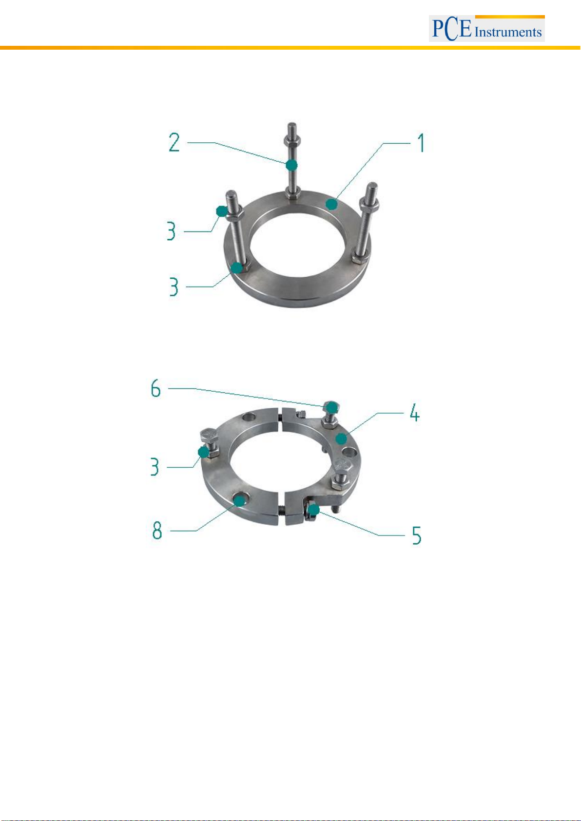
Fig. 2 Welding flange ........................................................................................................................................................8
Fig. 3 Clamping ring..........................................................................................................................................................8
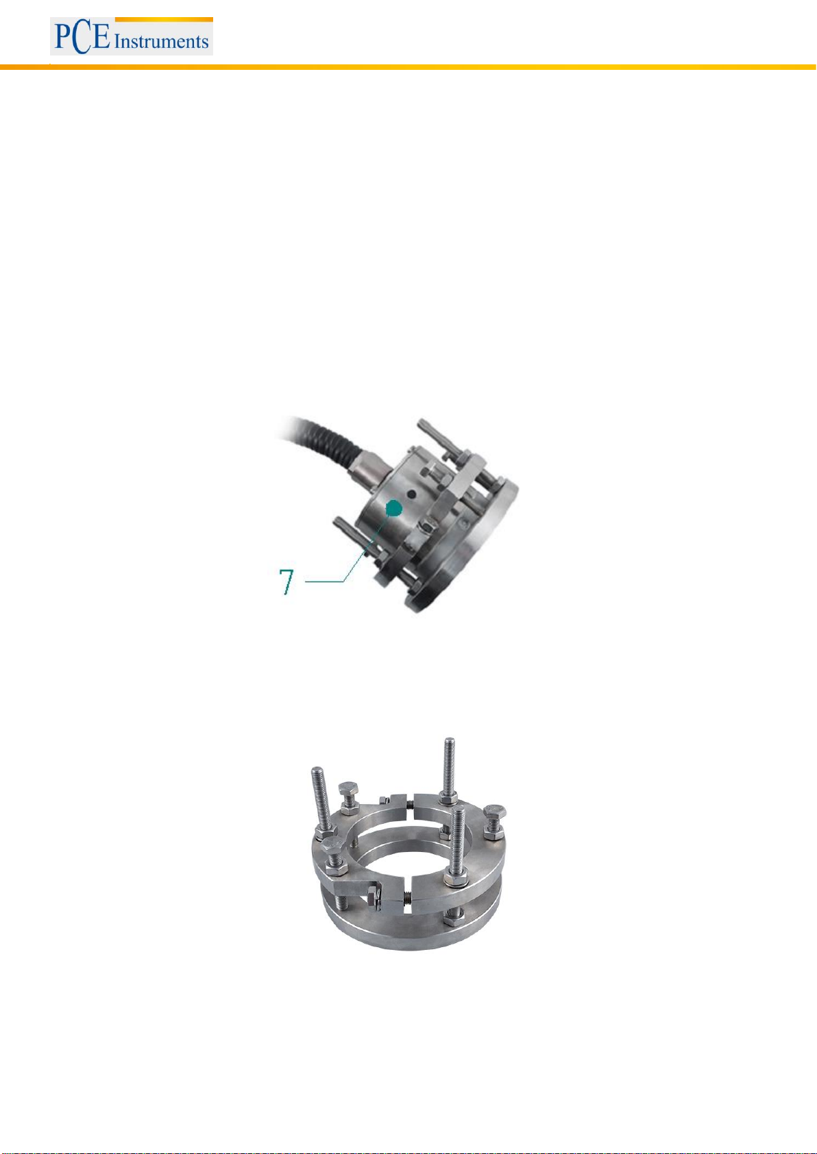
Fig. 4 Sensor fixed in ring-assembly.................................................................................................................................9
Fig. 5 Ring-assembly ........................................................................................................................................................9
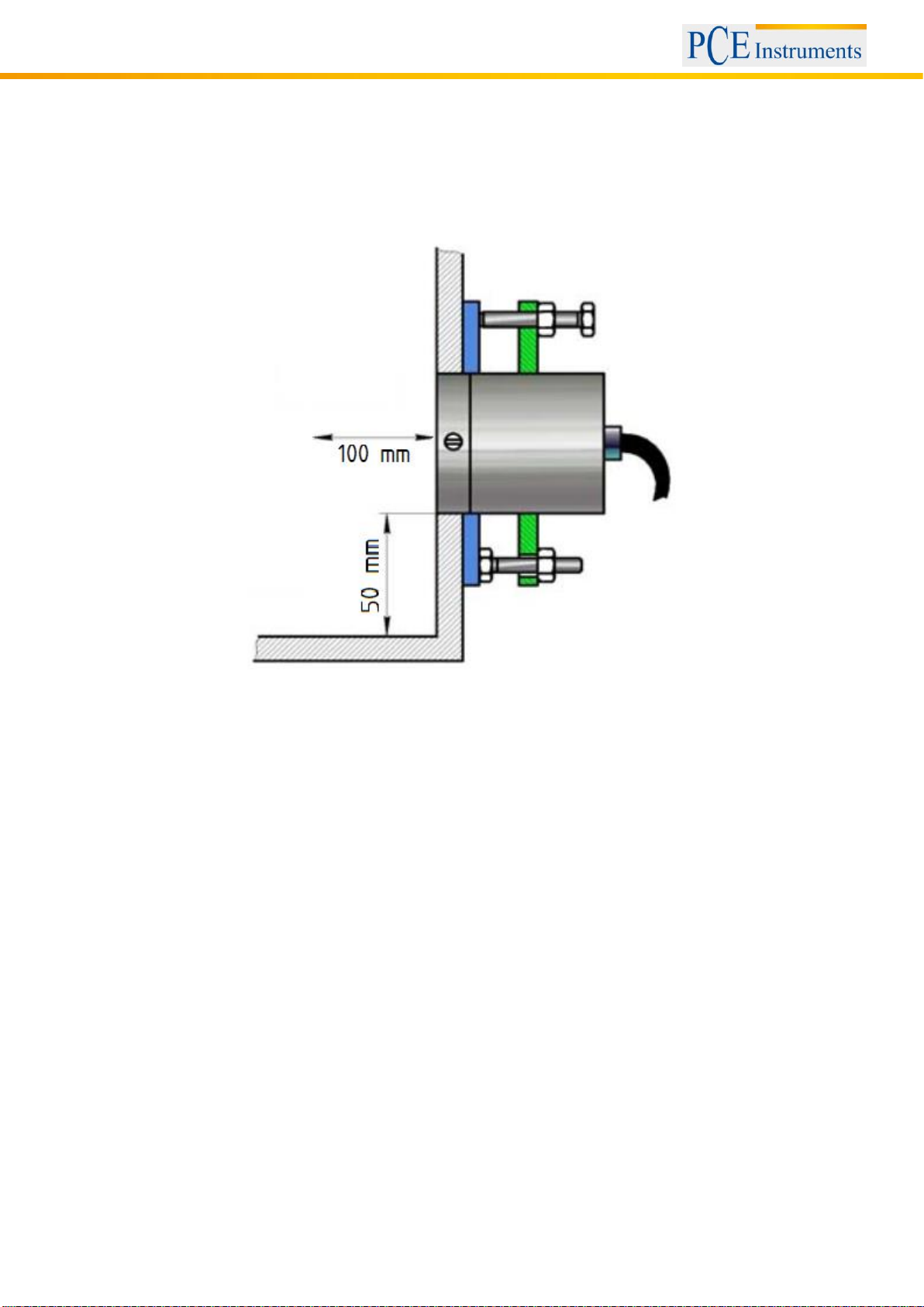
Fig. 6 Distance of PCE-MWM 210 to metallic components............................................................................................10
Fig. 7 Dimensions of the base plate of the moisture sensor PCE-MWM 240A ..............................................................11
Fig. 8 Dimensions of the rectangular cut-out ..................................................................................................................12
Fig. 9 Installation with welds ...........................................................................................................................................12
Fig. 10 Dimensions of the rectangular cut-out ................................................................................................................13
Fig. 11 Installation with screws .......................................................................................................................................13
Fig. 12 Dimensions of the rectangular cut-out ................................................................................................................14
Fig. 13 Dimensions of the flange for installation of the moisture sensor PCE-MWM 240A............................................14
Fig. 14 Installation on a curved surface ..........................................................................................................................15
Fig. 15 Sufficient material coverage of the moisture sensor PCE-MWM 240A..............................................................16
Fig. 16 Insufficient material coverage of the moisture sensor PCE-MWM 240A............................................................16
Fig. 17 Components of the moisture sensor PCE-MWM 240B ......................................................................................17
Fig. 18 Dimensions of the welding flanges .....................................................................................................................17
Fig. 19 Installation of the moisture sensor PCE-MWM 240B..........................................................................................18
Fig. 20 Sufficient material coverage of the moisture sensor PCE-MWM 240B..............................................................19
Fig. 21 Insufficient material coverage of the moisture sensor PCE-MWM 240B............................................................19
Fig. 22 M12 connector ....................................................................................................................................................21
Fig. 23 Wiring diagram....................................................................................................................................................21
Fig. 24 Pin assignment....................................................................................................................................................21
Fig. 25 Core identification code.......................................................................................................................................22
Fig. 26 Pin assignment for power supply........................................................................................................................22
Fig. 27 M12 connector ....................................................................................................................................................23
Fig. 28 Wiring diagram....................................................................................................................................................23
Fig. 29 Pin assignment....................................................................................................................................................24
Fig. 30 Core identification code.......................................................................................................................................24
Fig. 31 Pin assignment for signal output.........................................................................................................................24
Fig. 32 Pin assignment for analog output .......................................................................................................................25
Fig. 33 Pin assignment for serial port RS-485 ................................................................................................................26
Fig. 34 Calibration curves for different material ..............................................................................................................28
Fig. 35 PCE-MWM Manager main window.....................................................................................................................29
Fig. 36 Configuring RS-485 converter ............................................................................................................................30
Fig. 37 Settings ...............................................................................................................................................................31
Fig. 38 Successful connection ........................................................................................................................................31
Fig. 39 Message about missing initial calibration............................................................................................................31
Fig. 40 Configuration electronic unit ...............................................................................................................................32
Fig. 41 Dialog for initial calibration..................................................................................................................................32
Fig. 42 Initial calibration successful ................................................................................................................................32
Fig. 43 Tree view of calibrations .....................................................................................................................................33
Fig. 44 Window for new calibration.................................................................................................................................33
Fig. 45 Calibration table ..................................................................................................................................................34
Fig. 46 Warning if measured temperature of recorded date exceeds threshold.............................................................34
Fig. 47 Calibration table with first entry...........................................................................................................................35
Fig. 48 Assign moisture to sensor data...........................................................................................................................35
Fig. 49 Calibration table with multiple measurements ....................................................................................................36
Fig. 50 Calibration with high accuracy ............................................................................................................................37
Fig. 51 Calibration with reduced accuracy......................................................................................................................37
Fig. 52 Flawed calibration...............................................................................................................................................38
Fig. 53 Transfer calibration to electronic unit..................................................................................................................38
Fig. 54 Transfer best-fit line from electronic unit.............................................................................................................39
Fig. 55 Imported best-fit line from electronic unit displayed in the tree view ..................................................................39
Fig. 56 Currently selected calibration in the electronic unit ............................................................................................40
Fig. 57 Status bar for Test...............................................................................................................................................40