PCE Instruments PCE-N45F User manual

!
" !
WEIGHING CONTROLLER
Please read this manual carefully before operation
Model: PCE-N45F
PCE Americas Inc.
711 Commerce Way
Suite 8
Jupiter
FL-33458
USA
From outside US: +1
Tel: (561) 320-9162
Fax: (561) 320-9176
www.pce-instruments.com/english
www.pce-instruments.com
PCE Instruments UK Ltd.
Unit 11
Southpoint Business Park
Ensign way
Hampshire / Southampton
United Kingdom, SO31 4RF
From outside UK: +44
Tel: (0) 2380 98703 0 Fax: (0)
2380 98703 9
Weight Indicator

1
CONTENTS
1. Main specifications ............................................................................... 2
2. Dimensions ........................................................................................... 3
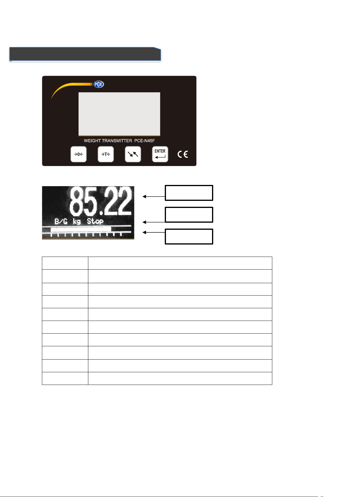
3. Front Overlay and Keypad .................................................................... 4
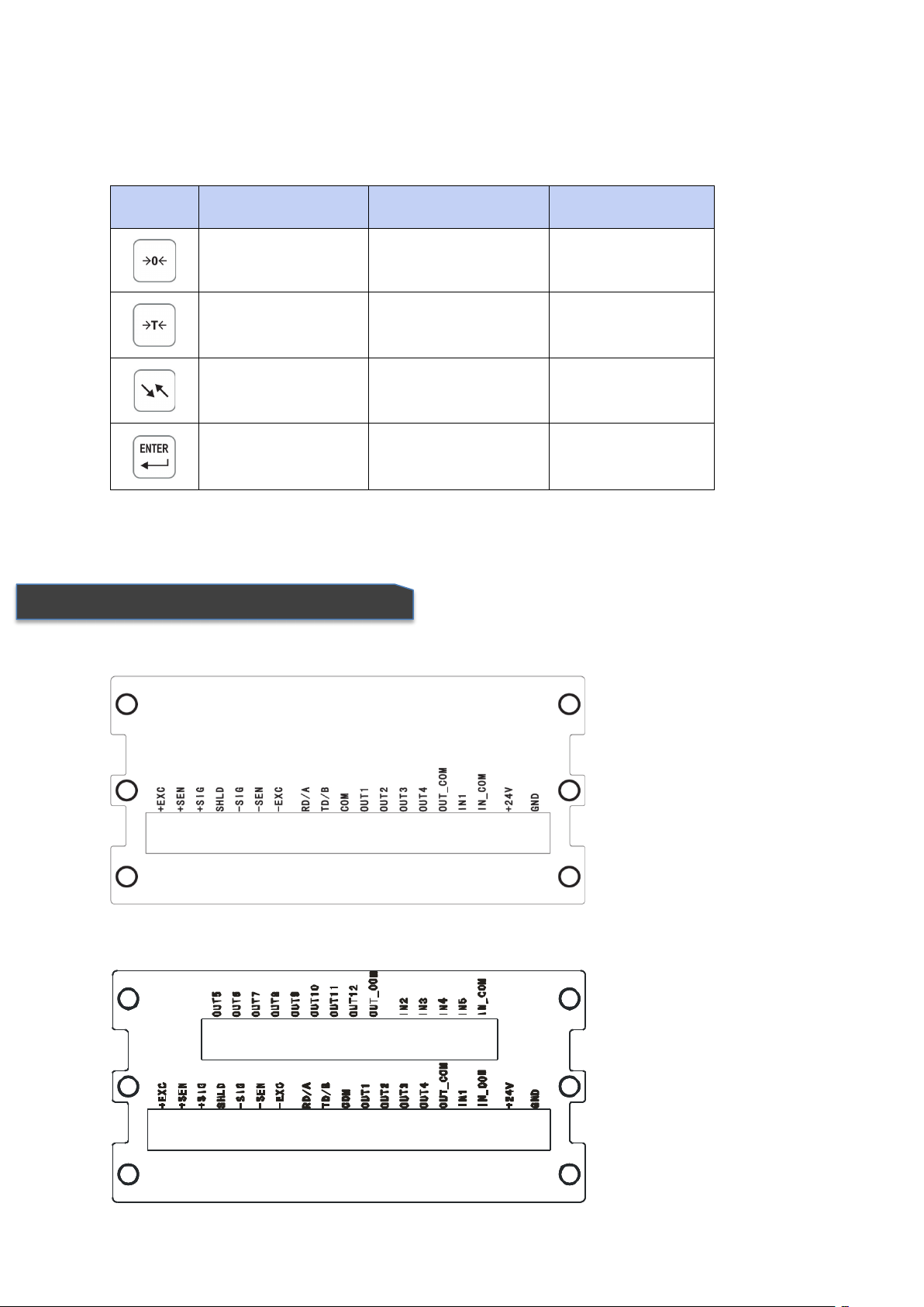
4. Rear Back Interface ............................................................................... 5
5. Load Cell Interface ................................................................................ 6
6. Serial Interface ...................................................................................... 7
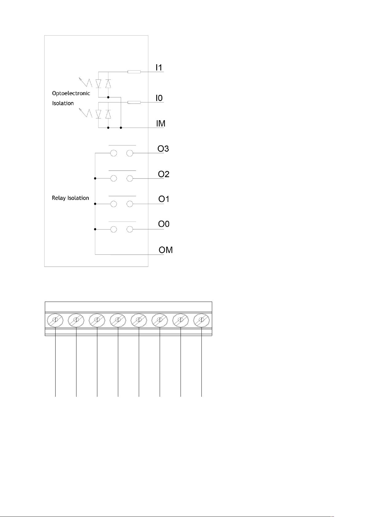
7. I/O ......................................................................................................... 7
8. Analog Quantity Output ....................................................................... 9
9. Parameter Set ..................................................................................... 10
9.1 Enter setting menu ........................................................................................ 10
9.2 Quit Setting .................................................................................................... 10
9.3 Main Set Menu .............................................................................................. 10
9.4 System Parameter Set ................................................................................... 10
9.4.1 Scale Set ................................................................................................................ 11
9.4.2 Operation Set ....................................................................................................... 14
9.4.3 Batching Set .......................................................................................................... 17
9.4.4 Communication protocol ...................................................................................... 23
9.4.5 Analog quantity output ........................................................................................ 25
9.4.6 Diagnosis and maintenance .................................................................................. 26
9.5 Recipes Parameters set ................................................................................. 31
9.6 Printing table format ..................................................................................... 35
9.7 System set ...................................................................................................... 35
10. Appendix: Communication Protocol ................................................. 36
10.1 Continuous transmitting format A .................................................. 36
10.1 Command transmitting Format A ............................................................. 36
10.2 Command transmitting format A ............................................................. 37
10.3 Continuous transmit format B .................................................................. 37
10.4 Command output format B ...................................................................... 37
10.5 MODBUS output format .............................................................................. 38
10.6 Multi materials jointed work with relay connected ................................. 41

2
1. Main specifications
Specifications
Housing
Metal shielded housing, with OLED display
dimensions(w ×h ×d)
110mm×62mm×116mm
Protection
IP65 (front panel)
Operation Condition
Temperature:-10℃~40℃
(14°~104° F)
Relative humidity:10%~95%,non-condensing
Power
+24VDC(±15%),Consumption <6W
Display
128×64 dot matrix、Yellow-Green OLED
Display resolution
Max.100,000
Platform
1 with analog load cell
Load cells
1~6 x 350 Ohm(Sensitivity is 2 or 3mV/V)
A/D Speed
200Hz (200times/s)
Excitation Voltage
5VDC
Min.Input sensitivity
0.6µV/d
Keypads
4 function keys
Basic
Serial Output:RS232 or RS485
I/O interface:1xIn 4xOut
Optional
I/O interface:4xIn 8xOut
Analog signal
0~20mA、4~20mA、0~24mA
0~10V、0~5V、-5~+5V、-10~+10V

3
2. Dimensions
Housing Dimensions
Installation dimensions
Installation hole size 92×45mm

4
3. Front Overlay and Keypad
Display
Signs
Status
Note
~
Stable, on for dynamic mode, off for static mode
B/G
Gross weight
Net
Net weight
Kg
Unit
Stop
Stop
Run
Run
M1
~
M4
Material 1-4
>>
Fast filling
>
Fine filling
Weight
Status
Percentage

5
4. Rear Back Interface
Keys’ functions for parameter set or choose
PCE-N45F
Keys
Menu
Parameter set
Parameter Input
Return
Return
Cancel and Quit
Up
Previous
Increase digits
Down
Next
Move right
Enter
Quit confirm
Quit confirm

6
5. Load Cell Interface
PCE-N45F-IO
PCE-N45F-DA
It can be connected with 6x350Ωanalog load cells (around 58Ωminimum resistance), to confirm the
range of the load cells, the total resistance (TSR) can be calculated with the formula as below:
Before connecting the load cells, make sure the TSR is above 58Ω, if it’s less, the indicator can’t work.
Besides this, the cable distance must be considered, too, below is the maximum distance suggested:
Load cell interface definitions:
TSR =
Input resistance(Ω)
Load cell numbers
TSR (Ω)
24# cable (m)
20# cable (m)
16# cable (m)
350
243
610
1219
58(6-350 W)
40
122
224
Pins
Signal
Note
+EXC
+Excitation
4-wire load cells short connected
+SEN
+Sense
+SIG
+Signal
SHD
Shield
-SIG
-Signal
-SEN
-Sense
4-wire load cells short connected
-EXC
-Excitation

7
6. Serial Interface
7. I/O
6-wire load cell or junction box 4-wire load cell or junction box
It has only one serial interface, to change it by switch for RS232 or RS485,method as below:
Pins
RS-232
RS-485
Bridge
Joint
Pin
signs
Rear
Front
Rear
Front
RD/A
RS-232 Receive
RS-485A
TD/B
RS-232 Transmit
RS-485B
COM
Ground
Blank
The basic type has one passive input and 4 relay open output
Basic type Pin’s definitions:
.
.
.
.
.
.
前盖板
后盖板
.
.
.
.
.
.
前盖板
后盖板
Pins
Signal
Note
OUT1
Output 1
Output properties:
AC:30~250VAC/1A
DC:5~30VDC/2A
OUT2
Output 2
OUT3
Output 3
OUT4
Output 4
OUT_COM
Output common port
IN1
Input 1
High level:10~24VDC
Low level:0~3VDC
IN_COM
Input common port

8
I/O interface drawing
Output – OM/O0/O1/O2/O3
Input – IM/I0/I1
PCE-N45F-IO has 4 passive input and 8 relay open output
OM
O2
O1
O3
I0
I1
IM
O0

9
8. Analog Quantity Output
Pins definitions:
PCE-N45F supply many types of analog signals which with proportional output according to the weight of
the scale
Pin
Signal
Description
OUT5
Output 5
Output properties:
AC:30~250VAC/1A
DC:5~30VDC/2A
OUT6
Output 6
OUT7
Output 7
OUT8
Output 8
OUT9
Output 9
OUT10
Output 10
OUT11
Output 11
OUT12
Output 12
OUT_COM
Output common port
IN2
Input 2
High level:10~24VDC
Low level:0~3VDC
IN3
Input 3
IN3
Input 3
IN4
Input 4
IN_COM
Input common port
Pins
Signal
Note
VOUT
Voltage output
Output resistance 0~600Ω, output can be:
0~+5V;0~+10V;-5V~+5V;-10V~+10V;
GND
Voltage output
IOUT
Electric
current output
Output can be:
4mA~20mA;0mA~20mA;0mA~24mA
GND
Voltage output
GND
SHLD
Shield

10
9. Parameter Set
9.1 Enter setting menu
On weighing mode,keep pressing key to enter parameter setting mode.
9.2 Quit Setting
On any mode,continuous press key to return to previous step or quit the setting mode.
9.3 Main Set Menu
Press key or key to select the
menu to be set, press key to enter
secondary menu, press key to quit the
set
9.4 System Parameter Set
Press key or key to select the
menu to be set, press key to enter
the chosen menu, press
key to return to previous step.

11
9.4.1 Scale Set
Press key or key to select the
menu to be set, press key to enter
the chosen menu, press
key to return to previous step.
Max.capacity
Range: 1~200000. Default:100.
Press key to move the cursor, press
to change the chosen digits, press
to save to return to previous step.
Press key to return to previous step
without change
Division
Division to be chosen:0.0001,0.0002,
0.0005,0.001,0.002,0.005,0.01,0.02,
0.05,0.1,0.2,0.5,1,2,5. Default: 0.001
Note: Only the below two conditions ok, the
chosen division can be accepted:
1:1000 =< F.S./Division = < 20000.
2:F.S./Division = multiple of 100.
Press or key to change the
division, Press Enter to save and
return, press key to return without
change
Calibration Unit

12
Press or key to change the
division, Press Enter to save and
return, press key to return without
change
Zero Calibration
Press key to return without change
Press or key to choose √or X,
If √chosen, press key to enter zero
calibration, or return directly.
When there is nothing on the scale and it’s
stable, press key to start zero
calibration.
The indicator is sampling the A/D data of
zero point, it ends when it became 0% from
100%.
Weight Calibration
Press key to return without change
Press or key to choose √or X,
If √chosen, press key to enter weight
calibration, or return directly.

13
Put the weight on the scale
Input the weight value the same as the
calibration weight
Press key to move the cursor.
Press key to change the digits.
Press key to save the change and
start to calibrate.
Press key to cancel and return.
The indicator is sampling the A/D data of
calibration point, it ends when it became 0%
from 100%.
The weight value is too small.
Trouble shooting:
1、 The weight is really too light.
2、Wrong connection of the signal
cable or excitation cable
Calibration done.
Full Calibration
This calibration is jointed the zero calibration and weight (capacity) calibration, prease refer
to above steps.
Calibration parameters

14
This parameter can be retrieved and can
be modified, after tested well, please record
those three parameters for use in future.
When the data in EEPROM get problem,
reload those three parameters, it doesn’t
need to do calibration again.
If the same model indicator to be changed
and those three parameters reloaded, it
doesn’t need to do calibration, either.
Input the weight value the same as the
calibration weight
Press key to move the cursor.
Press key to change the digits.
Press key to save the change and
enter next parameter.
Press key to cancel and return.
Expansion Display
If 10 times resolution display needed, open
the expand display:
Press key to cancel and return.
Press or key to chose √or X
Press key to confirm and return.
9.4.2 Operation Set
Press key or key to choose the
menu to be set, press key to enter.
Press key to return the previous step.

15
Tare Operation
Choices: Disable tare
Enable tare
Press or key to change
Press key to save and return.
Press key to cancel and return.
Zero upon Power on
Choices: 0%, 2%, 20%
Press or key to change
Press key to save and return.
Press key to cancel and return.
Zero by Keypad
Choices: 0%, 2%, 20%
Press or key to change
Press key to save and return.
Press key to cancel and return.
Zero Tracking
0:None;1:0.5d;
2:1d;3:2d;
4:3d;5:4d;
6:5d;
Press or key to change
Press key to save and return.
Press key to cancel and return.
Vibration checking

16
0:None
1:Vibration checking range = 1d;
2:Vibration checking range = 2d;
3:Vibration checking range = 3d;
4:Vibration checking range = 4d;
5:Vibration checking range = 5d;
Press or key to change
Press key to save and return.
Press key to cancel and return.
Digital filtering
Set range of 1-9, the more, the weight is more
stable and the longer time to be stable.
Normally, if the digital filtering number set to be
higher, the advance volume should be bigger, so
on the batching mode, the advance volume needs
to be adjusted again after the filtering number
changed.
Press or key to change
Press key to save and return.
Press key to cancel and return.
Buzzer Set
On or Off
Press or key to change
Press key to save and return.
Press key to cancel and return.

17
9.4.3 Batching Set
Press or key to chose the menu to
be set.
Press key to enter.
Press key to return previous step.
Batching mode:
Choices:4 materials batching
Single material weight lose
Free setpoint.
Press or key to change
Press key to save and return.
Press key to cancel and return.
Material quantity

18
If there is no I/O board, it can be set to be 1 only.
If there is the I/O board, it can be set from 1-4.
Press or key to change
Press key to save and return.
Press key to cancel and return.
Feeding door
1:single door single speed
2:double doors double speed
If there is no I/O board, only M1 can be set
Press key to move cursor.
Press key to modify the chosen digits.
Press key to save and return to previous
step.
Press key to cancel and return to previous
step.
Feeding mode
This parameter only valid for double doors and
double speed
All open: On fast feeding, open two doors at the
same time.
One open: On fast feeding, open fast feeding
door.
Press or key to change
Press key to save change and return.
Press key to cancel and return.
Feeding action
Choice:Auto or manual
Press or key to change
Press key to save change and return.
Press key to cancel and return.

19
Discharge mode
Choice:Auto or manual
Press or key to change
Press key to save change and return.
Press key to cancel and return.
Empty scale range
Choice:0%~9.9%×F.S
Only the weight on the scale is less than this
range and the cursor and output is effective,
otherwise it’s taken as not empty.
Press key to move cursor.
Press key to modify the chosen digits.
Press key to save and return to previous
step.
Press key to cancel and return to previous
step.
Frequency Adjust
Choice:0~9
When it set to be 0, it means no adjust
Press or key to change
Press key to save change and return.
Press key to cancel and return.
Time Parameter
Press key or key to choose the
menu to be set, press key to enter.
Press key to return the previous step.
Delay start time
Table of contents
Other PCE Instruments Accessories manuals