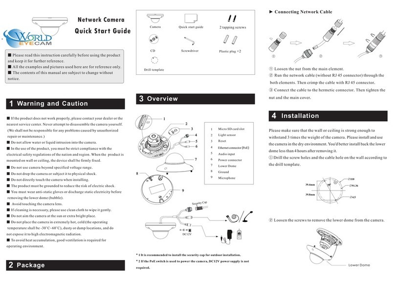
Pco pixelfly usb User manual

pco.pixelfly usb
pco.
user manual

PCO asks you to carefully read this manual before using the
pco.pixelfly usb camera system and follow the instructions.
In case of any questions or comments, please contact us at PCO.
telephone +49 (0) 9441 2005 50
fax +49 (0) 9441 2005 20
email info@pco.de
postal address PCO AG
Donaupark 11
93309 Kelheim, Germany
The cover photo shows an exemplary PCO camera system.
The lens is sold separately.
Copyright © 2016 PCO AG (called PCO in the following text), Kelheim,
Germany. All rights reserved. PCO assumes no responsibility for errors or
omissions in these materials. These materials are provided as is without
warranty of any kind, either expressed or implied, including but not limited to,
the implied warranties of merchantability, fitness for a particular purpose, or
non-infringement. PCO further does not warrant the accuracy or
completeness of the information, text, graphics, links or other items
contained within these materials. PCO shall not be liable for any special,
indirect, incidental, or consequential damages, including without limitation,
lost revenues or lost profits, which may result from the use of these materials.
The information is subject to change without notice and does not represent a
commitment on the part of PCO in the future. PCO hereby authorizes you to
copy documents for non – commercial use within your organization only. In
consideration of this authorization, you agree that any copy of these
documents, which you make, shall retain all copyright and other proprietary
notices contained herein. Each individual document published by PCO may
contain other proprietary notices and copyright information relating to that
individual document. Nothing contained herein shall be construed as
conferring by implication or otherwise any license or right under any patent or
trademark of PCO or any third party. Except as expressly provided, above
nothing contained herein shall be construed as conferring any license or right
under any PCO copyright. Note that any product, process, or technology in
this document may be the subject of other intellectual property rights
reserved by PCO, and may not be licensed hereunder.
Released: August 2016 © PCO AG
pco.pixelfly usb User Manual V2.12 © PCO AG, Germany

3
TABLE OF CONTENTS
TABLE OF CONTENTS
1. INTRODUCTION 5
1.1 INTENDED USE 5
2. SAFETY INSTRUCTIONS 6
3. SYSTEM COMPONENTS 7
4. INSTALLATION 8
4.1 DRIVER 8
4.2 CAMWARE 9
5. QUICK START 10
5.1 PREPARATION 10
5.2 START 10
5.3 YOUR FIRST IMAGE 11
6. CAMWARE 4 SOFTWARE 12
6.1 CHAPTER OVERVIEW 12
6.2 CAMERA OVERVIEW / LIST 13
6.3 CAMERA PROPERTIES 15
6.3.1 TIMING 16
6.3.2 IMAGE SIZE 17
6.3.3 SENSOR CONTROL 18
6.3.4 RECORDING CONTROL 20
6.3.5 CONVERT CONTROL DIALOG 21
6.4 IMAGE OVERLAY 23
6.5 RECORDER TOOLS 24
6.6 VIEW WINDOW 26
6.7 RECORDER (IMAGES) 27
6.8 SETTINGS OVERVIEW 29
6.8.1 AUTO SAVE 30
6.9 CAMWARE MENU TABS & FEATURES 32
6.9.1 DEMO MODE 32
6.9.2 FILE MENU 33
6.9.3 CAMERA MENU 35
6.9.4 ACQUISITION MENU 36
6.9.5 VIEW MENU 36
6.9.6 WINDOW MENU 37
6.9.7 HELP MENU 37
6.9.8 RIGHT-CLICK MENU 38
6.9.9 ADDITIONAL FEATURES 39
TOP

4
APPENDIX 40
A1 TECHNICAL DATA 41
A1.1 DATA SHEET 41
A1.2 MECHANICAL DIMENSIONS 42
A1.3 PINOUT OF RJ11 CONNECTOR 43
A2 TRIGGER INTERFACE 43
A3 HOT PIXEL UTILITY 44
A4 IMAGE FILE FORMATS 46
A5 CUSTOMER SERVICE 48
A5.1 SERVICE 48
A5.2 MAINTENANCE 48
A5.3 RECYCLING 48
A5.4 TROUBLE SHOOTING 49
A6 INDEX 50
ABOUT PCO 51

5
1. INTRODUCTION
1. INTRODUCTION
Advantages of the pco.pixelfly usb
Features
This versatile high performance 14 bit CCD camera system has
an extraordinary quantum efficiency of up to 62%. At the heart
of the camera is a FPGA processor which provides
sophisticated control and accurate timing of the CCD and
associated electronics. In addition, a proprietary offset control
algorithm has been developed which provides very high offset
stability, regardless of ambient temperature or signal
changes, ensuring accurate and repeatable quantitative data
over long periods of time.
The camera’s main features are:
•
resolution:1392 x 1040 pixel
•
superior quantum efficiency up to 62%
•
4000:1 dynamic range
•
superior low noise of 6e- rms @ 12MHz
•
no glow functionality at long exposure times
•
excellent DSNU at long exposure times
•
optimal offset stability and control (<1count)
•
hot pixel correction integrated
•
USB2.0 interface
1.1 INTENDED USE
This camera system is designed for use by technicians, engineers
and scientists. It is a scientific measuring instrument, which provides
images. The camera may only be used according to the instructions
of this manual. The disclosures and operating conditions in these
operating instructions installation must be respected. Unauthorized
modifications and changes of the device are forbidden for safety
reasons.
Areas of Application (Examples)
•scientific imaging
•material testing
•low light level imaging
•scintillation recording
•combustion imaging
•bioluminescence
•high resolution microscopy
•chemoluminescence
•luminescence spectroscopy
•flow visualization
•quality control
•machine vision
•
spectroscopy
•
imaging of bio markers
•fuel injection
•Red and NIR fluorescence
•particle image velocimetry
(PIV)
•industrial applications

6
2. SAFETY INSTRUCTIONS
Please read the safety instructions completely and follow them
always.
DAMAGED POWER CABLE OR POWER PLUG
Danger to life due to electric shock.
Each time the camera is used, check the power cable for
damage.
ELECTRIC SHOCK WARNING DUE TO VOLTAGE PARTS INSIDE
Risk of injury due to electric shock.
Never slide any items through slits or holes into the camera.
CONDENSATION
Risk of injury due to electric shock if condensation enters the
camera.
To avoid the risk of water condensation, protect the camera
against extreme changes of ambient temperature.
TRIPPING HAZARD
Risk of injury from tripping over loose cables.
Never position the cable in a way that it could become a
tripping hazard.
HUMID OR DUSTY ENVIRONMENTS
Humidity, dust or X-rays could damage the camera.
Never operate the camera in humid or dusty environments
or in places with high amounts of X-ray radiation.
SHOCK & VIBRATION
To prevent damage to the camera, the system must be kept stable
and protected against strong jolts or vibrations.
Use the mounting threads of the camera to mount the
camera stable.
LENS MOUNTING
Do not force the lens onto the camera.
To protect the lens connector thread from damage, use
minimal force when attaching a lens to the camera.
LIQUIDS DAMAGE CAMERA
If liquids have penetrated the device.
Immediately switch off the camera, separate it from power
line and contact our customer support.
DAMAGED CAMERA HOUSING
If the camera has been dropped or the casing is damaged.
Immediately switch off the camera, separate it from power
line and contact our customer support.
IF CAMERA IS NOT WORKING PROPERLY
If, after thoroughly reviewing the instruction manual, the device is still
not operating properly.
Immediately switch off the camera, separate it from power
line and contact our customer support.
NOTICE
NOTICE
NOTICE
NOTICE
NOTICE
NOTICE
DANGER
WARNING
CAUTION
CAUTION

7
3. SYSTEM COMPONENTS
3. SYSTEM COMPONENTS
The camera system includes the following parts.
Camera Head
C-mount optical connection:
The distance between the front edge of the c-mount and the sensor is
17.52 mm. For standard c-mount lenses and adapters.
DC Power Jack
(connect to power supply)
USB 2.0 Connector (connect to PC)
RJ11 (connect to I/O device)
LED indicates camera status
Green continuous: camera is ready
Green blinking: camera is in record
s
t
a
te
Red continuous: error /red blinking: boot lo
a
d
e
r
Red/green blinking: firmware upd
a
t
e
Serial Number Tag
Mounting Thread
3/8
''-
16 UNC 1/4"- 20 UNC
Trigger Interface (I/O Device)
Proprietary RJ11-BNC connector for Trigger/Busy/Exposure signals
Power Supply
AC to 12V/DC power supply
USB Cable
USB-A/USB-B cable (5 m)
Digital Camera Tools (USB storage device content)
•Camware: software for camera control & image acquisition
•Camera driver & tools
•Software development kit (SDK) & demo programs in C and C++

8
4. INSTALLATION
You will find all necessary files on the accompanying USB storage
device. You may also download the newest versions of our software,
camera driver and third party software drivers from our Website
(www.pco.de).
Minimum system requirements:
•Clock speed > 1.6 GHz
•1280 x 1024 pixel
resolution display
•RAM > 512 MB
•Windows 7
•USB 2.0
4.1 DRIVER
Please start the USB 2.0 driver installation from your pco.usb flash
drive. Don’t connect the camera to your computer before driver is
completely installed.
Run the provided installation file and follow the instructions of the
installation wizard.
After finishing the driver installation wizard please connect your
pco.pixelfly camera to its power supply and via enclosed USB 2.0
cable to your computer.
The first time the camera is connected via USB to your computer,
Windows will notify the user that a new device has been detected.
NVIDIA Cuda Driver:
Please update your NVIDIA driver for Camware 4. In case of an old
driver version GPU Processing is not working. Therefore image
processing is slow.
Please check if GPU Processing is activated by
having a look into the Proc config settings in
the Convert Control window (see Convert
Control chapter 6.3.7).
If GPU Processing is disabled and shown
grayed, please update your NVIDIA driver. Your
NVIDIA driver version must be at least 333.11 or
higher.
1
2
1
2
3
4
3
4

9
4. INSTALLATION
4.2 CAMWARE
The Camware Windows application software enables you to control
every camera parameter or setting. Images can be displayed on a
monitor and may be downloaded and stored. The USB storage
device contains the installation files for the software for latest
Windows operating systems in 32 & 64 bit.
After a successful installation, you will find the program file Digital
Camera Toolbox in your program directory and a Camware32/64
button on your desktop. Other helpful tools are also installed in the
same directory.
To uninstall the Camware program, please use the Software feature
under Windows’ System Control.
Please follow the installation wizard
-Install Camware as Admin to install to program folder, instead it
will be installed only to user folder.
-Then choose install directory.
-Choose components: Select additional drivers.
-After the next two screens installation is complete.
1
2
3
4
1
1
2
3
4

10
5. QUICK START
In order to get familiar with your new camera and software it might be
helpful, if you first aim at an object that is easy to focus and that can
be seen at standard light conditions.
5.1 PREPARATION
•Computer is turned on
•Installation is finished (see chapter 4)
•An appropriate lens is attached (remove cap) or the camera is
attached properly to the microscope, spectrograph or other
scientific device
•Camera is connected to the PC
•Camera is connected to the power supply and ready (LED green)
5.2 START
Start Camware and the graphical user interface will start up:
NOTE
Always install latest Camware version to be able to use full
function of your pco camera.

11
5. QUICK START
5.3 YOUR FIRST IMAGE
Please follow the instructions:
•Camware must be started.
•A view window is shown automatically / or open a new one.
•Start live preview.
•Right-click in the view window and apply Auto Range Peak.
•You may adjust exposure time , aperture and focus.
•Now you should clearly see the object in the window.
If you need to change
exposure time (e.g. the image
is still either too dark or too
bright), please go to chapter
6.2
If you want to record and save
images, please see chapter
6.3.4 and chapter 6.9 for
detailed information.
NOTE
Live preview: Useful for fast and easy camera adjustment and
focusing.
2
3
4
5
6
2
3
6
4
5
1
1

12
6. CAMWARE 4 SOFTWARE
PCO’s Camware is excellent software for camera control,
image acquisition and archiving of images in various file
formats. This chapter provides a detailed description of
all Camware functions.
Camware works with any kind of PCO camera. Please
see PCO website for the latest version of this software.
6.1 CHAPTER OVERVIEW
Chapter 6.2: lists all cameras connected
6.2 Camera Overview/List
Preview, connected cameras, recording
profiles
Chapter 6.3Camera Properties:main dialog for all camera settings:
6.3.1 Timing
Timing settings / Trigger modes /
Synchronization
6.3.2 Image Size
ROI / Sensor format / Binning
6.3.3 Sensor Control
CDI / Double Shutter / temperature
6.3.4 Recording Control
Recorder Acquire Mode / Timestamp /
Sequence trigger
6.3.5 Convert Control
Contrast, Saturation, Gamma…
Chapter 6.4/ 6.5 /6.6 /6.7 / 6.8 describe the recording functions
6.4 Image Overlay
Overlay for recorded images
6.5 Recorder Tools
Record / Play and Settings
6.6 View Window
View window functions
6.7 Recorder (Images)
Preview of recorded images
6.8 Settings Overview
Overview of all property settings / Auto
Save
Chapter 6.9describes all tabs, the right-click menu and additional
features.
6.9.1 Demo Mode
No camera connected
6.9.2 File
Open, save and print files
6.9.3 Camera
Camera control;Rescan, Setup…
6.9.4 Acquisation
Live preview; Acquire sequence; Rec.
memory settings; Rec. settings
6.9.5 View
New window; Convert Control
6.9.6 Window
New / close / split window
6.9.7 Help
Logfiles, Support file, About
6.9.8 Right-click menu
Zoom; Flip; Mirror; Rotate…
6.9.9 Additional features
White Balance, Contrast, Short Cut list

13
6. CAMWARE 4 SOFTWARE
6.2 CAMERA OVERVIEW / LIST
If closed, the Camera Overview window
can be opened by selecting the View tab
and Toolbars and Docking Windows →
Camera Overview.
The Camera Overview window allows you to manage several
connected cameras. It displays a list of all connected PCO
cameras. Camware is able to scan 2 for connected cameras or
close a connected camera. It is possible to define several different
Settings for each camera (max. 30 sets per camera →add new
set 3 ).
New view windows 4 can be opened and the Live Preview 5
function can be started. When unfolded, the Preview shows a
small preview window 6 (always monochrome) integrated in the
camera list.
Live preview enables the adjustment of aperture and focus and to
have a first look at your object. During live preview no images are
saved into the computer RAM.
During Live preview Trigger and Acquire mode are set to Auto.
Camera Setting: All Preferences that have been made in the
Camera Properties (see 6.3) are saved to Camera Settings. Define
different Settings with different Preferences in Camera Properties
for each of your experiments. Settings can be switched easily at any
time (not during record) and can be copied to other cameras.
Link Preview Set to ‘Preview’
When Link Preview Set to Preview is activated the Preview
set with its parameters will always be active when you start a
Live Preview 5 .
In case this function is deactivated the Live Preview will
always show live images with the parameters of your active
setting.
This feature can be of great advantage if preview light
conditions are different from those in recording situations.
1
1
2
3
4
2
3
4
5
5
6
6
5

14
1
2
3
Click and drag camera setting: If you want to copy e.g. Camera
Setting 1 to Camera Setting 4, just drag Setting 1 to Setting 4 and
Camware will ask you if you want to copy the settings. It is possible
to copy each setting to every camera.
Master Sets
This function facilitates the image acqusition with multiple
cameras. Define two or more Master Sets to switch during an
experiment very easily between different predefined settings for
each camera. Each image acquisition or experiment can be
recorded with its own Master Set.
To display Master Sets, please right-click in the Camera
Overview window and select Show Master Sets.
Master Set window
Define different Master Sets. Select individual Camera Settings
within each Master Set.
Functions:
Add Master Set or Remove active master .
Put it to active status by clicking on one of your sets .
Important Setting (for cameras without internal memory)
Memory Allocation Dialog
If you want to change the number of recorded images in
Camware, you have to open the Acquisition Tab (see 6.9.4)
and choose Recorder Memory Settings.
This sets the number of images recorded in one sequence. The
maximum is defined by approved RAM size.
1
2
3

15
6. CAMWARE 4 SOFTWARE
1
2
3
6.3 CAMERA PROPERTIES
The Camera Properties window in Camware is the main interface for
all camera settings. The active set selected within Camera List can
be adjusted here.
The former main instance Camera Control (known from Camware
3.x) and the Convert Control (see 6.3.5) can be opened additionally.
Three view options with various functions can be selected: Standard,
Custom and Expert.
Standard mode 1 only shows camera name, type, set, serial number
and exposure time. Exposure time is the only parameter that can be
changed. It is recommended for new Camware users.
Custom mode shows several more setting possibilities and
functions can be hidden or shown by the Custom Properties
Button.
Additional to the standard mode, Trigger mode, Image Size and
Recording control options are selectable.
Expert mode (for advanced users) shows all possible camera
property settings.
An explanation for every setting is displayed below the properties
dialog.
1
2
4
3
4

16
t
td
: trigger acknowledge delay t
id
: intrinsic delay
tread: readout time texp: exposure time
6.3.1 TIMING
Trigger Modes
Auto Sequence The camera will optimize the image recording
to achieve the best possible frame rate.
In the Auto Sequence exposure control mode, the camera
determines the fastest possible frame rate depending on the
adjusted exposure time and the required readout time.
After a start command is given, the sequential recording is
started until a stop command is given.
Software Trigger Single images can be recorded with this
Camware command. A single image can be acquired by
pressing the Single Trigger button. This button appears after
pressing the Start Record button (see 6.5). Other signals cannot
influence this operating mode.
External Exposure Start The image acquisition is triggered by
an external signal. It is also possible to force a software trigger
for a test image with the Single Trigger button.
In the External Exp. Start exposure control mode, single image
recording is started by the rising/falling edge of the voltage signal at
the BNC input (see appendix A1.3, A2).
pixel clock intrinsic + trigger acknowledge delay
12 MHz / 24 MHz 5.6 µs
Exposure Time and time-base
It is possible to change time-base from automatic to µs or ms. If
your input is out of the range of the camera, it will be
automatically changed to the next possible setting. The current
frame rate (fps) is always displayed. The exposure time (delay
time is not available for pco.pixelfly usb) can be adjusted in
steps of 1 μs. The jitter of the actual exposure start edge: < 13
ns.
camera type exposure time
pco.pixelfly usb 1 µs … 60 s
2
trigger
busy
exposure
t
id
ttd
t
exp
t
read
2
1
1

17
6. CAMWARE 4 SOFTWARE
2
1
3
6.3.2 IMAGE SIZE
The actual image size 1 is displayed here. Binning or Region
of Interest settings affect the image size and are applied
automatically.
Binning
Binning combines neighboring pixels (in either the horizontal or /
and vertical direction) to form super pixels. It increases the light
signal of the resulting pixels and decreases the spatial
resolution of the total image which is recorded.
Since the readout is done only once for all binned pixels, the
signal to noise ratio increases. Vertical binning will also increase
the readout speed (x2 vertical binning = double frame rate).
Available Binning Modes:
H1xV1, H1xV2, H1xV4, H2xV1, H2xV2, H2xV4, H4xV1, H4xV2,
H4xV4
Sensor Format
This sensor implementation provides the option to either read out the
standard size of 1392 x 1040 pixels (effective pixels recommended by
the sensor manufacturer) or an alternative size of 800 x 600 pixel
(center mode).
2
3
1

18
6.3.3 SENSOR CONTROL
Sensor Control allows controlling of all sensor specific settings.
Double Image / Doubleshutter (optional)
This feature is widely used for particle image velocimetry (PIV)
measurements and is an optional feature. The first exposure
time texp1 can be any exposure time of the available range of the
pco.pixelfly usb camera. The second exposure time texp2 can not
be directly adjusted. The length of the second exposure is
exactly determined by the readout time treadA of the first image.
The interframing time titf denotes the transition time between
end of exposure #1 and start of exposure #2. Readout times
treadA and treadBare exactly the same. See also appendix A1.3.
While recording in Double Shutter mode, Camware will
automatically split the view window and always shows both
images beside each other.
Double Shutter timing
t
td
: trigger acknowledge delay t
id
: intrinsic delay
texp1: exposure time 1st image treadA: readout time 1st image
texp2: exposure time 2nd image treadB: readout time 2nd image
t
itf
: interframing time
trigger
busy
exposure
tread B
t
id
t
td
t
exp1
texp2
titf
tread A
1
12 MH
z
24 MH
z
ttd +
t
id
5.6
µ
s 5.6
µ
s
t
exp
1µs … 60s
1µs … 60s
t
read
137 ms
74 ms
t
itf
1
µ
s
1
µ
s
1
2
2
3
4
5

19
6. CAMWARE 4 SOFTWARE
IR Sensitivity
This feature uses a special image sensor control
method, allowing greater sensitivity in the near
infrared spectral range (red line in graph), in most
cases at the expense of decreased anti-blooming
performance
.
Minimum exposure time is 5 ms. It is recommended to
use the IR sensitivity mode for long exposure times
>120ms
The integrated hot pixel correction is only active for
standard mode. If
y
o
u
need to correct hot pixels in IR
mode, please follow instructions in chapter 6.9.3
(Create Hot Pixel List). Or see A1.3.
Pixel Clock
The pixel clock sets the clock frequency and therefore the image
sensor readout speed.
At 12 MHz the image quality will be higher due to very
l
ow readout
noise
(
rea
d out at a higher b
an
dw
i
d
t
h
)
.
At 24 MHz the image sensor is read out with nearly double speed,
achieving higher frame rates.
Conversion Factor
The conversion factor defines how many charges (electrons), which
have been generated by light in each pixel, are necessary to generate
one count (one intensity level) in the digital image. Therefore, the
conversion factor describes the gain when converting electrons into a
digital value.
The pco.pixelfly has two conversion factors: 1.0 e-/count and 1.5 e-
/count, which both can be used in standard and binning mode. As
mentioned in 6.3.2 binning is available for the pco.pixelfly. The usable
extended fullwell-capacity rises in binning mode from 16000 to
24000e-. In standard mode it makes sense to keep 1.0e-/count; if you
change the conversion factor to 1,5e-, you can’t use the high dynamic
of 16384 grey scale. In binning mode you can use both conversion
factors: If you have a lowlight scene the 1.0e-/count mode helps you
to spread the few available information – in normal light scenes it
makes sense to use 1.5e-/count for full dynamic availability.
Resolution
12 MHz
24 MHz
1392 x 1040
7.3 fps
13.5 fps
800 x 600
11.7 fps
21.6 fps
3
4
5

20
3
4
5
6.3.4 RECORDING CONTROL
Recorder Mode
In Sequence mode the recording stops if the number of
allocated images in RAM space is reached. (See 6.2). In Ring
Buffer mode the camera will stop only by a stop command. In
this mode the RAM is a circular buffer and overwritten again and
again.
Timestamp
A time stamp can be placed into the upper left corner of the
image. It can be either switched off, binary or binary with text.
The time resolution is 1μs.
In binary mode the first 16 pixels will be filled with the time
stamp information (binary code). The numbers are coded in
BCD with one byte per pixel, which means that every pixel can
hold 2 digits. If the pixels have more resolution than 8 bits, then
the BCD digits are right bound adjusted and the upper bits are
zero. For further information please refer to the SDK.
In binary and ASCII mode text will be placed into the image
replacing the content of the image (271x 8 pixels).
Time stamp shows the end of exposure time.
Three different information is stamped onto the image: number
of the image , date and time .
Additionally to Timestamp the Image overlay function is
available, see chapter 6.4.
3
4
5
1
2
1
2
Other manuals for pixelfly usb
1
Table of contents
Other Pco Security Camera manuals
