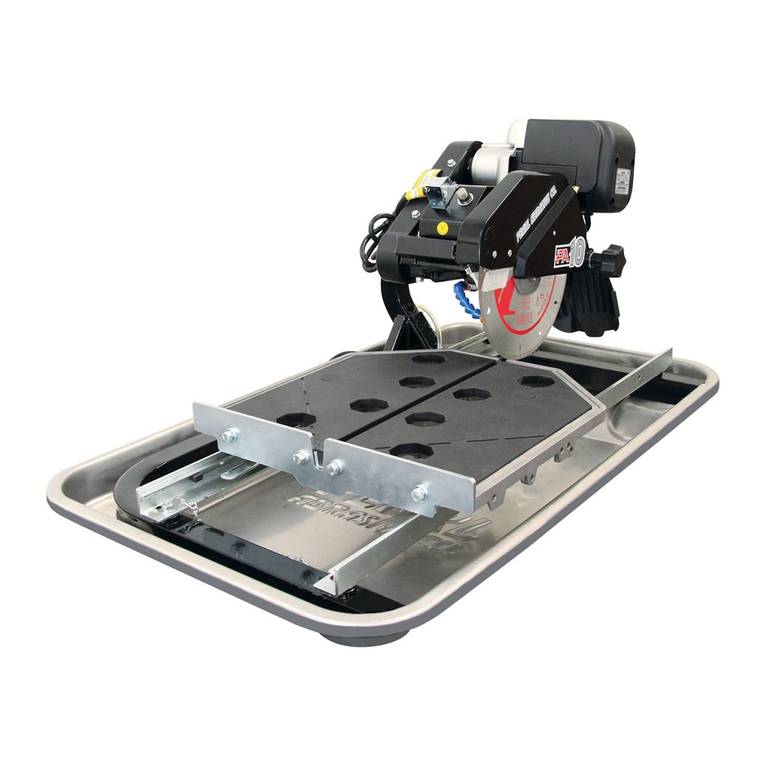
Pearl Abrasive VX7.2XL Owner's manual

YVI
\-1
illrulilBrn
You
should
record
theSerialNumberof
your
Tile
Sawon
this
0wner's/0perator's
Manual
andontheWarranty
Card.
TheWarranty
Cardmustbesentbackwith
alltherequired
pertinent
inlormation.tor
thewarranty
totakeetfect.
CaUtiOn! nealSafetyand
General
lnstructions
caretultybetoreusingsawforthelirsttime.
PatentsPending
Assembledin
U.S.A.

CO]ITElTTS
Pqge
I GencrolScfety Rulcs
for fill Powcr Tools . . . . . 3
it Symbols ....'4
iii. Fcotgres ......5
iv. Specificctions.. ....5
Y. Gettingto Know your Sow . . . . 5
v[ Blodelnstqllotion... .....7
viL Sofe
Operoting
Proctices
for TileSqw. . . . . . .7
viii. OsingthecuttingToble '....1O
xix, Coreqndllointenonce... ....11
x. Becringl{oosingfieplocement.. '.'.13
xi. CuttingDcpth. ...13
xil BeltRcplocement. ....14
xiii. (eplocementPqrtlists. .'..14
xiv. f,ccessories... ..19
xy. TheRight
BlodcsDoesthc Right
tob. . . .2O
xvi l{ow to OrderParh . . . . 20
xvil Electricoll.lotor
Specificotion.. ....21
xviilTioubleshooting ....22

i. GETIERf,L
SfIFETY
RUTES
FOR
fiLLPOWERTOOLS
o
A
N
@
@
@
@
@
@
D
@
n
1.Know
y0ur
power
tool
-read
owner's/operator's
manual
carefully.
Learn
its
applicationsand
limitations
as
well
as
the
specific
potential
hazards
unique
tothistool.
2.Keep
guards
in
place
-
and
inworking
order.
3.
Ground
alltools
-
iftoolsareequippedwiththree
prongplug,
it
shouldbe
plugged
into
a
three-hole
electrical
receptacle.lf
anadapter
is
used
to
accommodatea
two-prongreceptacle,
theadapterlugmust
beattached
toa
known
ground.
Neverremovethethird
pr0ng.
4.Remove
wrenches
-Formahabitofcheckingtoseethatadjustingwrenchesareremovedfromtool
before
turningit
"0n".
5.
Keep
work
areaclean.
Cluttered
areasandbenches
invite
accidents.
6.Do
not
use
in
dangerousenvironment.
Donot
use
power
toolsin
dampor
wetlocations,
orexpose
themto
rain,Keepwork
area
welllighted.Donotusetoolinthe
presence
of
flammableliquids
or
gasses.
7.Keep
childrenand
visitors
away.
All
childrenand
visitorsshouldbekept
at
asafedistancefromwork
area.
8.
Makeworkshop
childproof
with
padlocks,
master
switchesor
byremoving
starter
keys.
9.
Donotforcetool.ltwill
do
the
job
betterandbesaferatthe
rateforwhichitwas
designed.
10.
Use
righttool.Donotforcetoolorattachmenttodoa
job
forwhichitwasnot
designed.
11,Wear
proper
apparel.
Donotwearloose
clothing,
gloves,
neckties,rings,
bracelets
or
other
jewelry
thatmay
get
caught
inmoving
parts.
Non-slipfootwearisrecommended.Wear
protective
haircoveringto
contain
longhair.
12.
Always
usesafety
glasses.
Wear
safety
glasses
(must
comply
with
ANSI287.1)atall
times,
Everyday
eyeglassesonly
haveimpactresistantlenses;they
are
notsafety
glasses.
Usefaceordust
maskif
cutting
operation
is
dusty,andear
protectors
(plugs
or
muffs)
during
extended
periods
ofoperation.
13.Donotoverreach.
Keep
proper
footing
andbalanceatall
times,
14.Maintaintoolsintop
condition.
Keeptoolssharpandclean
for
bestandsafest
performance.
Follow
instructionsforlubricating
andchangingaccessories.
lnspecttoolcords
periodically
andifdamaged,have
repaired
byauthorizedservice
facility.
15.Disconnecttools.Whennotin
use,beforeservicing,and
when
changingaccessories,such
asblades,bits,
cutters.
16.Avoid
accidentalstarting.Makesureswitch
isin
"off"
position
before
plugging
in
power
cord.
17.Userecommended
accessoriesonly.Consult
theowner's
manualforrecommended
accessories.
The
use
of
improper
accessories
may
cause
risk
of
injuryto
persons.
18.Never
standon
tool.
Seriousinjurycouldoccur
ifthetoolistipped
or
ifthe
cutting
toolis
accidentally
contacted.
19.
Check
DamagedParts.
Beforefurtheruseof
thetool,
a
guard
orother
part
thatis
damagedshouldbe
carefully
checkedto
ensure
thatitwill
operate
properly
and
perform
it'sintendedfunction.
Check
for
alignmentofmoving
parts,
bindingof
moving
parts,
breakageof
parts,
mounting,andanyotherconditions
thatmay
affect
it's
operation.A
guard
or
part
that
is
damagedshouldbe
properly
repaired
or
replaced.
20.Neverleavetoolrunning
unattended.Turn
power
"off".
Do
notleavetool
until
it
comes
to
acompletestop.
-3-

o
/l
[l
O
o
o
g
A
A
21.
Extension
cords.
Makesure
your
extension
cord
isin
good
condition.
Whenusing
anextension
cord,be
sure
to
use
one
heavyenough
to
carry
thecurrent
your
product
willdraw.
An
undersized
cord
will
cause
a
drop
inline
voltageresulting
inlossof
power
andoverheating.
Extensioncord
tables
(referto
page
2/)show
the
correct
size
to
use
depending
oncord
lengthand
nameplateampere
rating.
lfin
doubt,
use
the
next
heavier
gage.
The
smaller
the
gage
numbers
theheavier
the
cord.
22.Do
not
abuse
cord.
Nevercarry
toolbycord
or
pull
itto
disconnect
fromreceptacle,
Keepcord
fromheat,
oil,and
sharp
edges.
23.Guard
against
electric
shock.
Preventbody
contact
with
grounded
surfaces.
Forexample,
pipes,
radiators,
rangesand
refrigerator
enclosures.
24.
Outdoor
useextension
cords.
When
tool
is
used
outdoors,
use
onlyextension
cords
intended
for
use
outdoors
and
so
marked.
25.Stay
alert.
Watch
what
you
aredoing.
Use
comm0n
sense.
Donotoperate
tool
when
you
are
tired.
26.Drugs,
alcghol,
medication,
Do
notoperate
toolwhileunder
theinfluence
ofdrugs,
alcohol
0rany
medication.
27.
Store
idle
tool.
Whennot
in
use,
toolshouldbe
stored
inadry
and
locked
place,
out
ofreach
ofchildren.
@
@
@
@
@
@
E
@
KEEPGUARD
INPLACE
DIAMOND
BLADE
BLADE
CUTTING
DEPTH
ELECTRIC
SWITCH
OFF
ELECTRIC
SWITCH
ON
ELECTRICAL
HAZARD
REMOVE
TOOLS
PAYEXTREME
ATTENTION
ii. SYMBOLS
REPAIRS
TOBE
DONE
MACHINE
HAZARD
FLAMMABLE
READ
INSTRUCTIONS
CAREFULLY
WARNING
FRAGILE
KEEP
DRY
DO
NOT
STEP
ON
WEARHEARING
PROTECTION
WEAR
EYE
PROTECTION
WEAR
BREATHING
PROTECTION
WEAR
HARD
HAT
WEARPROTECTIVE
CLOTHING
WEARSAFETY
SHOES
WELL
VENTILATED
NONON-WORKING
PERSONNEL
w
A
N
El
A
A
6
@
-4-

a
a
o
a
a
iii.FEfiTORES
ThePearl
VX7.2X1
/VX
10.2X1is
a
portableprofessional
tilesaw.
Lightweightandcompact
ithasinnovativebuilt
in
features
that
enable
itto
cut
largerformat
tiles.Theunique
maintableallow
the
saw
toincrease
its
cutting
capacity
when
needed.
Themaintableandextension
carriagearesupported
by
lowfriction,
self
cleaning,adjustable
guide
wheels.
Water
flowtothebladeis
provided
by
two
(2)
nozzlesthat
directs
thewatertobothsidesof
the
blade.
The
rugged
powder
coatedsteel
framesets
in
a
removablehigh-impact
ABS
watertubforeasycleanup.
Powertil
Motor
- 1-1/2hp
(VX
10.2X1)&3/4
hp
(VX
7.2X1)
Automatic
Thermal0verload
prntectsyour
saw
from
plwer
surgesand
m0t0rlverheating
HighImpact
ABSWater
Tray
withstandseven
thetoughest
punishment
AdjustableCutting
Headallowsuser
toalignsawatany
time
Cutting
alignment
notatfected
bywatertray
maintenance
BladeCapacity
-8"
t010"
(VX
10.2X1)&7"
(VX
7.2X1)
Diagonal
cutup
t0l6" tilesand
ripcutup
t0
24"inlength
The
heavy-duty,cast
tolast,
construction
and
quality
components
were
designed
tomeetthe
highest
demands
of
the
professional.
Readthis
manualcompletely
and
thenlet
thePearl
VX7.2X1//X
10.2X1take
your
cutting
capabilities
to new
dimensions.
iY.SPECIFICf|T|OifS
'Width:
22.5'
Height:
18.5'
Width:22.5'
Height:
19.25"
Counter-
Clockwise
Counter-
Clockwise
5/8"arbor
blade,
| 58lbs.
7"Blade I
I
I
5/8"arbor
blade,
I 83
lbs.
8,9&
10"Blade
314
HP
115
v,
60
Hz,
Single
phase
1-1t2HP
115
v,60Hz,
Single
phase
-5-

Y.GETTITTG
TO K]IOWYOOR
SfiW
-6-

1.Carefully
raisethe
cuttingheadtoitshighest
position
andsecureitinto
place
by
tightening
thecutting
head
adjustment
knobintherear
su
pport.
Raisetheblade
guard
tothehighest
position
and
tightenthe
blade
guard
adjustment
knob.
Removethe bladeshaftnutandouter
flange.
Place
the
bladeonto
the
shaftmakingsurethat
the
directionalarrowsare
pointing
in the
directionof
rotation.
Aftermaking
sure
thatthe
blade
isfirmly
placed
against
theinnerflange,
secure
itinto
place
withtheouterflange
andbladeshaft
nut.
Makecertain
thenutiffirmly
tightened
with
the
wrench
provided,
butdonotovertighten!
Lowertheblade
guard
andtightenthe
adjustment
knob,
Slightly
loosentherear
supportadjustment
knob,
lower
thecuttingheadsothattheblade
is3/16"
t01/4"
belowthesurfaceof
the
cutting
table,and
thentighten
theadjustment
knob
firmlytoholdthe
cutting
headin
place.
1.
Usesafetyequipment
-wear
safetyapproved
hearing,
eye,
head
andrespirator
protection.
2.Read
andunderstand
the
symboldefinitions
contained
inthismanual.
Yi.BLfDE I]ISTfiLLFTIO]I
WARNING:
Settingthebladeloolowmay
damagethe
cutting
table
and
if
settoohigh,
theblademay
grab
thematerial
beingcut,
causingdamageand
possibly
injury.
3. Readand
understandall
warningsand
instructions
on
themachine.
4.Readallsafetymaterials
and
instructionsthat
accompanyanybladeoraccessoryusedwith
thismachine.
5.
Establish
a
training
pr0gram
for
alloperations
ofthismachine.
6.
Always
provide
acopyofthis
manual
tothe
equipmentuser.lf y0u
needextracopies
callour
CustomerService
Department
at
1-800-969-5561.
7.Always
selectadiamondbladeaccording
to
themanufacturersrecommendation
suitable
forthematerialto
becut.
Never
useablade
havingamaximumoperating
speed
lowerthan
the
"No
load
R.P.M."marked
onthetool
2
J.
4.
5.
7.
8
Figure1
Vii.Sf,FE
OPERf|TIIIG
PRFCTICES
FOR
TIIE Sf,W
-7-

-
nameplate.
Do
notoperate
any
saw
without
safety
guards
in
place
or
with
ablade
diameter
larger
than
themaximum
saw
blade
capacity'
8.
Before
mounting
ablade
on
thesaw
clean
and
inspect
thearbor
shaft,
blade
flanges
and
the
diamond
blade
foruneven
wear
ordamage.
lf
itappears
tobedamaged,
Do
notoperate
the
tool. Have
itserviced
by
aqualified
service
technician.
9.
Before
each
use
of thesaw,
inspect
the
diamond
blade
for
hairline
fatigue
cracks.
lf
such
acrack
or
flaw
isevident,
discard
the
blade.
Using
a danaged
blade
nay eause
iniury
totheoqerator
or otherc'
10.
Besure
that
theblade
arbor
hole
matches
the
blade
adapter
flange
supplied
with
the
saw'
Use
only
blade
adapter
flanges
that
came
on
your
saw.
Never
use
damaged
or
w0rn
blade
adapter
flanges.
11.
tnstatting
theblade,
install
the
blade
with
the
arrow
pointing
thesame
direction
as
the
rotation
of
thearbor
shaft
or
thearrow
on
the
blade
guard.
Besure
totighten
theblade
shaft
arbor
nut with the wrench
provided'
Becareful
nottoover
tighten'
12.Check
that
theblade
tracks
near
the
center
of
thechannel
in
themain
table,and
that
the
table
moves
freely
from
front
toback.
13,Sometimes
the
material
being
cut
is not
abrasive
enough
toexpose
new
diamonds
on
theblade.
lfthe
blade
isnot
sharpened,
it
will
rubagainst
thesurface
resulting
inheat
build
up
in
thecore.
To
prevent
this,
it
isnecessary
todress
theblade.
Todress
theblade
simply
cut
something
that
isvery
abrasive
such
as
a
piece
ofcement
block.
Indications
that
the
blade
needs
dressing
includes:
. Thediamond
in
the
matrix
appear
shiny
because
theY
are
worn
flat.
. Theblade
stops
cutting
0r noticeably
slows
down.
Btade
dressing
stones
are
available
from
your
local
Peail
Warehouse.
14.
Beforeusing
thesaw
fillthe
water
tubenough
tosubmerge
the
water
pump
with
clean
water
only.
Replenish
as
necessary
and
clean
the
water
tub
frequently.
Do
notoperate
a wet
cutting
blade
without
adequate
water
flow
to
both
sides
of
theblade.
Never
run
the
pump
dry.
15.
Whencutting,
always
hold
the
material
firmly
lying
flat,supported
by
the
main
table
with
one
edge
resting
against
the
main
tablebackstop'
. Do
notattempt
to
cut
pieces
toosmall
to
safely
hold
down
on
the
main
table.
. Never
use
the
side
of
theblade
tocut
or
grind
with,
only
cut
inastraight
line.
. Keepall
parts
of
your
body
away
f
rom
the
blade
and
all
other
moving
Parts.
. Never
touch
or
trytostop
amoving
blade
with
your
hand.
16.
Whencutting
dry
- always
unplug
the
water
pump
tvst. llever
run
the
PumP
drY'
. D0
notuse
awetcutting
blade
fordry
cutting.
Select
the
proper
dry
cutting
blade
for
your
aPPlication.
. Never
make
long
continuous
cuts
withdry
cutting
blades.
To
avoid
heat
build
up,
allow
the
blade
tocool,
remove
the
tile
and
allow
the
blade
torun
freely
fora
few
minutes.
17.
Make
certain
alladjusting
knobs
or
locks
are
tight
and
engaged
in
theirdetents
and
that
movable
parts
not
intended
tomove
during
operation
aresecurely
locked
before
making
a
cuL
Becareful
nottoover
tighten'
18,Before
connecting
the
machine
to a power
source
check
tosee
that
the
"0n/0ff"
switch
is
in
the
"off"
position.
@@@p@@tr

(B)
Coverof
g
rounded
outletbox
(c)
ry
''fi::ly
\\
(Lus)
Metal
Screw
Figure
2
Grounding
Methods
. Makesure
theblade
isnotcontacting
anything
before
connecting
toa power
source
andstarting
themotor.
. Knowhow
to
stop
themachine
quickly
in
case
ofanemergency.
1
9.Grounding
Instructions
.ln theevent
of a malfunction
or
breakdown,
groundingprovides
a
path
0f
least
resistance
forelectric
current
to
reduce
theriskofelectric
shock.
This
tool
isequipped
with
an
electriccord
having
an
equipment-grounding
conductor
and
a
grounding
plug.The
plug
mustbe
plugged
intoa matchingoutlet
thatis
properly
installedandgrounded
in
accordance
with
alllocalcodes
and
ordinances,
. Donotmodify
the
plug
provided
-
ifit
will
notfit
the
outlet,
havethe
proper
outlet
installedbya
qualified
electrician.
. lmproper
connection
of
theequipment-
grounding
conductor
can
result
in
a
risk
ofelectric
shock.
. Check
witha qualified
electrician
0r
service
personnel
if the grounding
instructions
are not completely
understood,
or
ifin
doubt
as
towhether
the
toolis
properly
grounded.
. Use
only3
wireextension
cords
that
have
3 pronggrounding
plugs
and
3 Pole
receptacles
thataccept
thetool's
plug.
Bepairorreplacedamaged
orworn
cord
immediately.
Thistool
isintended
for
useon
acircuit
thathasanoutlet
thatlooks
liketheone
illustrated
inFigure2.
Ihetoolhas
a
grounding
plug
thatlooks
likethe
plug
illustrated
in
Figure2(A).
Atemporaryadapter,
whichlookslike
the
adapter
illustrated
inFigure2(B)and
2(C),
may
be
used
toconnect
this
plug
to
a
2
pole
receptacleasshown
in
Figure
2@
rt
a
properly
grounded
outlet
isnotavailable.
The
temporaryadapter
should
beused
onlyuntil
a
properly
grounded
outletcan
be
installedbya
qualified
electrician.
The
green-colored
rigidear,
lug,
and
thelike,
extending
from
theadapter
mustbeconnected
to a
permanent
ground
suchas
a
properly
grounded
outlet
box.
Additionally,
water
pump
requires
the
use
ofaGround
Fault
Circuit
Interrupter.
Therefore,
whenusing
thewater
pump
receptacle,
thistoolmustbeplugged
intoa
properly
installed
Ground
FaultCircuit
Interrupter
outlet.
See
Figure
2(D).
lf a Ground
FaultCircuit
lnterrupter
outlet
is
not
available,
Pearl
AbrasiveCo.
hasitavailable
asan
accessory
item.A plug-in
Ground
FaultCircuit
lnterrupter
maybe
plugged
intoa
properly
installed
and
grounded
3-poleoutlet.
Referto
Figure2(E).
20.Positionof
the
Tile
Saw
. Toavoid
the
possibility
of
theappliance
plug
orreceptacle
getting
wet,
position
tilesaw
tooneside
ofawall
mounted
receptacle
to
prevent
waterfromdripping
onto
thereceptacleor plug.The
user
should
arrange
a
"drip
loop"in
the
cord
connecting
thesaw
toareceptacle.
The
"drip
loop"is
that
part
of
thecordbelow
the levelof the receptacle,or the
connector
ifanextension
cord
isused,
to
prevent
watertravelingalong
the
cord
and
coming
incontact
with
thereceptacle.
See
Figure3.
. lfthe
plug
orreceptacle
does
get
wet,
Donotunplug
thecord.
Disconnect
the
Grounding
pin
-9-

fuseorcircuitbreaker
thatsupplies
power
tothe
tool.Thenunplug
andexamine
for
presence
of
waterinthe
receptacle.
21.
ExtensionCords
. Use
only
extension
cords
thatare
intended
foroutdoor
use.
Theseextension
cordsare identified by a marking
"Acceptable
for use with outdoor
appliances;
store
indoors
whilenot in
use."
Useonly
extension
cords
having
an
electrical
ratingnot
less
thanthe
ratingof
the
product,
Refertochart
on
page
21.
Do
not
use
damaged
extension
cords,
Examine
extension
cordbefore
using
and
replace
if damaged,
Do not abuse
extension
cords
anddo
not
pull
onany
cord
todisconnect.
Keepcord
away
from
heat and sharp edges.
AIwaYs
disconnect
the
extension
cord
from
the
receptacle
beforedisconnecting
the
saw
fromtheextension
cord.
Yiii.
osFtc THE
Features:
. Cutting
table
markedin
inches
for
precision
cuts,
. l4"cutting
table
provides
moresupport
during
largercutting
jobs
thanthestandard
11"
cutting
tables.
Using
90'Rip
Guide:
1.
Set
the
rip
guide
by
positioning
it on
the
desired
dimension
and
tighten
the
threaded
knob.
Makesure
thatthe
rip
guide
isfirmly
tightened
to
avoid
slippage.
Therip
guide
can
beused
for90'
rip
cuts
fromboth
theleftand
rightside,
2.After
the
rip
guide
is
positioned
forthedesired
cut,
place
material
flatagainst
the
rip
guide
and
the
table
measurement
rail.
3. Simply
line-up
thematerialbeing
cut
with
the
appropriate
pre-marked
lineson
thecutting
tablesurface,
4. Now
you
are
ready
tomake
your
cut.
. Ground
Fault
Circuit
Interrupter
(GFCI)
protection
shouldbe
provided
0nthe
circuit(s)
or outlet(s)
to
be
used
forthe
tilesaw.
Receptacles
areavailable
having
built-inGFCI
protection
and
maybeused
for
thismeasureof
safetv.
Supporting
Surface
COTTID{G
TfiBtE
Making
MiterCuts
(Using
Optional
Miter
Block):
1.For
mitercuts,
place
thelipof
themiterblock
on
themeasurement
rail,with
the
threaded
knobs
facing
you.
2. Tighten
the
threaded
knobs
to
secure
the
miter
block
in
place.
3, Placematerial
onto
miterblock
and
you
are
ready
to
cut.
Figure
4
Cutting
largetile
VX
10.2X1andVX
7.2X1cancut
a
24"
tileanddiagonally
cuta
16"tile.
- 10
-

xix. CfiRE
FffD llfiF{TENf,NCE
The
PearlVX7.2NX
10.2X1requiresvery
little
maintenancehowever,
keeping
y0ur
sawcleanand
properly
adjustedwill
ensure
optimum
performance.
Take
great
care
notto
get
waterinto
themotor.Donot
use
pressure
washerto
cleanmotor
area.
1.
Cleaning
. Form
ahabit
of
cleaning
your
sawafter
each
use.
To
cleanthewatertub,remove
drain
plugprovided
in bottomof tub.
Remove
saw
including
water
pump
from
tub.Remove
residualwater
andcleantub
usingsoapandwater
only.
Reinstall
saw
with
pump
intotub.
.
Toincreasewater
pump
liferemovetile
grit
by
purging
water.Pumpwithfresh
water
aftereachuse.
. With
adampcloth
orsponge
wipe
clean
the
guide
rails
andall
othersurfaceson
the
saw
where
dust
anddebris
has
accumulated.
2.
Transporting
. Unplug
the
power
cord
andstore
itinthe
empty,drywatertub. For
convenience
andsafety,the
sawshouldbe
transported
with
boththemaintable
andcarriage
locked,motorin
upper
position
andall
adjustmentknobstightened.
3.Sliding
Carriage
Adiustment
. Make
sure
that
all
rails
and
rollers
are
clean.
. lf carriage
and/or
table
doesnot
slide
smoothly,it will require
tension
adjustment
as
follows:
A.Raise
saw
2"-3"
fromtable
or
workbench
(front
and
rear)
gaining
acces
to (red)
pivot
adjuster
bolts.SeeFigure5.
B.Locate
(red)
pivot
adjusteronframe
base.
Adjustroller
tension
against
extrusion
carriage
byloosening
socketheadbolt
directlybelow
adjuster.
See
Figure
5.
C.
With
boltloose,turn
(red)
pivot
adjuster
Pivot
Adjuster
(red)
Slidingcarriage
adjustment
(314"
wrenchisneeded)
either
counter-
clockwise
(putting
theroller
intothe
extrusion)
orclockwise
(pulling
theroller
awayfromthe
extrusion.)
D.Tightenlower
hex-boltwhenfinished.
E.
Since
fourrollers
areadjustable
onbase,
all mayneed
attentionat operator's
discretion.lfthetableisnotrunningfreely
or
feelsloose,
sometimes
itis
difficultto
discernwhich
one
needs
adjustment.The
simplest
procedure
istoloosen
ALLfour
adjusters
and
re-adjustin sequential
order:
a.
Right
SideMiddle
b.
Right
Side
Rear
c.Right
Side
Front
d.
Left
SideMiddle
Be
sureto
check
forlooseness
orbinding
aftereachroller
adjustment.
4.Table
RollerAdjustment
A.Loosen
(4)
hex-screws
0n
table
top.
B.Adjust
tension
on
rollers
byturning
set
screw
(on
outsideoftable)
untildesired
tensionis achievedD0 N0T
0VER-
TfGHTEN.
SeeFigure
6.
C.
Re-tighten
the
(4)
screws
on
tabletop.
Checktablemovement
andre-adjustif
necessary.
Table
shouldrollfree
but
without
sidemovement.
- 11
-

4hex-screws
Figure
6
Table
rolleradiustment
STEP
1
5.
Aligning
the
Bladetothe
Table
.Whilecutting,
thematerial
being
cut
must
move
inastraight
line
parallel
tothesaw
blade.
lf
theblade
isoutof
plane
itwill
bind
at
oneend
of
thecut.
Toalign
the
blade
requirescutting
a tile
(securely
against
the tableback
stoP)
while
checking
forbinding
at
trailingedge
of
blade
(farthest
away
fromoperator).
See
Figure
7.
Figure
7
Blade
lf adjustment
is required,
loosen
four
bolts
at top of verticalarm. Rotate
complete
motorassembly
asrequired
until
alignment
is
attained.
Tighten
all
fourboltsand
re-checkalignment.
6.
Tub&
Tray
. Insert
thelarge
rubber
stopper
inthe
drain hole. See Figure 8.
FigureI
7.Positioning
theSaw
inthe
Tub
A.Place
thesaw
inthe
tub
positioning
the
Vertical
Armon
thesame
side
as
therelief
inthe
tub
shown
in
Figure
10.
Figure9
Attaching
DripTray
toTub
Tile
B.Line
the
saw
up
with
the
molded
guides
in
thebase
of
the
tub.
Rubber
Stopper
-12-

I
I
II
II
8.Connecting
theWater
Pump
A.Attach
the
provided
adapter
tothewater
pump.
B.Hand
tightentheadapter.
Donot
use
a
wrenchas
it
can
strip
thethread.
C.Connect
the
clear
tubingto the
male
section
of
the
adapter
until
itfitssecurely
See
Figure11.
x. BEfiRhrG
HOOSING
ToRemove
theBearing
Housing:
1.Remove
the
screws
(5
screws-VX
7.zKl'
3screws-Vx
10,2X1)on
thebelt
guard.
2.Remove
the
belt
guard.
3.
Loosen
(but do not remove)
the
adjustmentscrew
behind
the
mounting
plate
and
the4screwson
the
motor
base
to
removethebelt.
4.Remove
the
blade
lock
nut
and
remove
the
blade
(if
there
is
one
present).
5.
Remove
the4 screws
on
themounting
plate
closest
tothecutting
head
handle
to
remove
thebearing
housing
(including
the
attached
pulley
and
inner
flange.)
To
Installthe
NewBearing
Housing:
1.
Be
sure
that
you
havecompleted
the
instructions
above
to remove
theold
bearing
housing.
2.
Open
the
boxand
carefully
place
theflat
portion
of
the
new
bearing
housingface-
downon
atowelsituated
ona
flat
surface.
3.Secure
the
cutting
headinacompletely
horizontal
position.
4.Slide
thenewbearing
housing
withthe
flat
Xi.COTTI]IGDEPTII
Therecommended
cuttingdepth
is1/4"below
the
cutting
tablesurface.
To
adjust
thecuttingdepth,
loosenthe
mounting
plate
adjustment
knobso
thattheblade
is1i4'
below
thetopof
thecutting
table's
surface.
WA4MNG:
Setting
thebladetoo
lowmaydamage
the
cutting
tableand
if set
toohigh,theblade
may
grab
the
materialbeingcut, causing
damageandpossibly
injury.
Water
REPLfiCEl.IElIT
portion
facing
upwards
onto
the4
screws
locatedbelow
themounting
plate.
Take
care
notto damage
theinner
flange.
Lock
the
bearing
housinginto
place
by
using
bracketsand
nuts.
5.
Pullthemotor
toward
you,
place
thebelt
onthe
pulleys,
and
tightenthe
motor
position
adjustment
screw.
Besure
to
leave
someslack
on
the
belt.
6.
Alignthebeltbyadjusting
themotor
pulley
after
loosening
thehex
screw.
WARNING:
Donotadjustthebearing
housing
pulley.
After
aligning
thebelt,
tightenthe
hex
screw.
7.Replacethebelt
guard
and
lockinto
place
using3screws.
1-112inch
1-3/4inch
2-114inch
2-314inch
10inch 3-1/4
inch
- 13
-

1.
2.
Turn
offthe
saw
before
proceeding
anyfurther.
Loosen
andremove
the
belt
guard
screws
and
take
offthe
belt
guard.
3. Loosenthe
4 nuts
(front
& back)
onthe
mounting
plate.
Gentlyloosen
themotor
adjustment
clip
onthe
very
rear
ofthe
motormounting
plate.
Carefullynudge
the
motor
slightlyforward,
so
there
is
a
little
slackinthe
belt.
Take
offthe
oldbelt
andreplace
with
new
belt.
Xii.BELT
REPLFCEI'IETIT
Xiii.REPIFCEI'IE]IT
PfiRTSLIST
7. Tore-assemble,
follow
stepsinreverse
order.
Figure
13
4.
5.
6.
VX 7,2xL MOTOR ASSEMBLY -,23,
.{[
@-- /'
PARTNAME
1 Power
Cable PABTNUMBEN
PSVO701
0PABT
NAME
18 Blade
GuardAdjustment
Knob PANT
NUMBEB
PSV07022
2 314HP
ElectricalIndustrial
Motor
3 Motor
ShaftPullev PSVO7015
4 Motor
Adiustment
Qlip
with
Screw PSV0Z025
5 MountinoPlate
6 Belt
GuardBracket
7 Ti4ing
T
ShapeNylon
Belt
8 Belt
Guard
9 Belt
Guard
Screws
{5)
'10 Blade
Shaft
11 Blade
ShaftPullev
12 Bearing
Housinq
Hold
DownBracket
PSVO701
419 CircuitBreaker PSV07024
PSVO7026
2o Power
Toqole
Switch psvooool
21 Power 0Z
(lncludes:
Toggle
Switch,
CircuitBreaker,
Power
Cable)
PSVO701
723 Motor
Protection
CoverShield PSV07035
PSV07032 24 Carbon
Brushes
(set
of
2) PSV07036
PSVO70'16 25 Brush
Caps PSV07037
PSV07033 26 Bearino
Housino
Screws
&Nuts pSV07038
PSV00003 27 WaterFlow
"T"
Adaoter PSV00005
PSV0701
I28 WaterFlow
"L"
Adapter pSV00008
29 Rubber
Splash
Guard PSV0Z023
PSV00006
PSV0001
1
PSV00040
PSV00009
13 Liquid
CooledBearinq
Housinu pSV00007 30 Water
Pump
14 Inner
Flanoe pSV07030 31 Pullev
LockPin
15 0uterFlange PSVO7031 32 Water
Tubing
16 Blade
LockNut PSV00004 33 7'Blade
-14-
[a-,t
@)
17 Blade
Guard PSV07021 DTLOTBl
9

vx 10.2xL
MoToR
ASSEMBLY
PABTNAME
1 Power
Cable PABTNUMBEB
PSV1
001
0PABTNAME PABT
NUMBER
19 Rubber
SplashGuard PSV10023
20 CircuitBreaker PSVl
0024
PSV1
0012 21 Toggle
Switch
PSV1
0013 22 Power
SwitchHousino
PSV1
001
4
PSV]
0015 PSVl0027
PSVl
0028
PSV1
001I 27 Blade
Shaft PSV00003
Zg l-iquiO
CootedBearin
29 Bearino
attachedtoInner
Flanqe PSV10029
2 MotorFan
Cover PSV10011
3 Running
Capacitor PSV00001
4 StarterCapacitor PSV00002
5 1-112
HPElectricalIndustrial
Motor 23 MotorAdiustment
Clip PSV10025
24 MountinqPlate PSV10026
6 Motor
Shaft
Pullev
7 Belt
Guard PSV10016 25 #25RubberBell
8 Belt
GuardBracket 26 Bearing
attachedtoPullev
9 Motor
SupportShaft PSVl
0018
10 Blade
ShaftPullev
11 PullevLock
Pin PSV00011
12 BearingHousing
HoldDown
Bracket PSV00009 30 Inner
Flanoe PSVl
0030
PSVl
0020 31 10Blade DTL1
OB19
PSVO0008 32 Outer
Flanoe PSV10031
PSV1
0021 33 BladeLock
Nut PSV00004
PSV1
0022 34 WaterPumo
PSV00008 35 WaterTubinq
PSV00005 36 Belt
GuardScrews
(3) PSV07033
13 Blade
CleaninqBrushes
(Z
ea.)
14 WaterFlow
"L'
Adapter
15 Blade
Guard
16 Blade
GuardAdiustment
Knob PSV00006
17 WaterFlow
L Adaoter PSV00040
18 WaterFlowT Adapter
- 15
-

VX 7.2xJ. VERTICAL ASSEMBTY
PABT
NAME
VX 1O.2XL VERTICAL ARM ASSEMBLY
ARM
',-;\
1 Arm,Vertical PANT
NUMBEB
v380101-MA PANTNAME
Arm,Vertical PABTNUMBEN
v380101-MA
2 Mount,
Motor v380102-MA
3 HexBolt,
.375
-16x1
Grade
5Min. 2 Mount,
Motor
10"
4 Washer,
.375A.N.
Flat.65
0.D.Max. v3801 3 Hex
Bolt,.375
-16x1
Grade
5+
5 Dowel
Pin,.250x.5 v3802 4 Washer,
.375
A.N.Flat
.65
0.D.Max. v3801
6 Set
Screw,.375
-16x.5 v3803 5 SetScrew,.375
-16x.5
6 DowelPin,
.250x.5 v3802
vx 7.2xL
MAIN ASSEMBLY
PANT
NUMBEN
v31
000
v31
100R
3 CuttingHead
4 Shaft,Pivot v380103-MA
5 TableAssemblv v380000
6 Vertical
Arm
Assemblv v3801
00
7 StandardKnob v381
7
8 Washer.
Flat v3805
I HexBolt,
Grd.
5Min.375
- 16UNCx3 v3806
10 HexBolt,
Grd.5Min.375
-16UNCx3.5 v3807
11 Standard
Knob v381
7
12 Bumper
Slop
'13SocketHead
CapScrew,
Plated.250x.625
-16-
12142

%
vx 10.2xL
MAIN ASSEMBLY
PANT
NAME
1 BaseAssemblv PABT
NUMBEN
v31
000
2 CarriageAssembly v311
00R
3 TableAssembly v380000
4 Washer,
Flat:.375
SAE
5 HexBolt,
Grd.5Min..375
- 16UNCx3
6 Hex
Bolt,
Grd.5Min .375
- 16UNCx3.5 v3807
7 Bumper
Stop
8 SocketHead
CapScrew,Plated.25
-20UNC
x.625
9 T-Bolt
12142
v380207
10 10"
CuttingHead
'11
Vertical
ArmAssemblv v380200
12 ShaftPivot v380202-MA
13 Handle.
Adiustable 6270K34
14 Fender
Washer,
Metric v3811
'15
Bolt,.1Omm
x25 v381
2
16 Washer,Lock
1Omm v381
3
vx7.2x|. & vx 10.2xL
TABLE ASSEMBLY *le
tr
u
R
II
tl
U
rI
PART
NAME
1 MainTable PANTNUMBEB
v380001-MA
2 Mount,Roller v31014-MA
3 Spacer.Roller v31004-MA
4 Washer,
Coined v31005-MA
5 NutPlate,
Table v3'101s-MA
6 Roller
Assemblv v31003
7 ButtonHead
Screw..25x1UNC v3814
8 FlatHead
Socket,.25-20x1.5 v381
5
gn
tl
-17
-
9 SetScrew,.25-20x1.25 v381
6

vx7.zxt & vx lo.2xl
CARRIAGE ASSEMBLY
PABTNAME
Extrusion,
Carriage PARTNUMBEN
v31
008R
rew,Sockethead114-20x6.2 12140
Shim
(0ptional) v31
018
End
Casting v31009-MA
vx7.2xt & vx 10.2xL
BASE ASSEMBLY
@L'
TT
?
-r
T
/h-,
T
aa6)
Y@
e
I
YT
I
e
IT
I
-]-
T
6.\
YT
-r
I
g
,ffi
Zr
lfr'l
il[,i
ililrl
l]ltP n
I
YT
-A
N.4
,^
Y
'>./
--..-{e
PARTNAME PABTNUMBER
12139
{0 1 Screw.
Buttonhead114-20x1.25
2 Washer,
Coined v31005-MA
3 Spacer,Roller v31004-MA
4 Roller
Assemblv v31
003
5 Base,
Sub-Assembly v31000
6 Caps,Tubing 12138
7 Pivot.Adiuster v31002-MA
8 Screw,Sockethead
5116-18x2 12178
9 Bushing,Pin
Lock v31016-MA
10 Chain
11 Pin,Lock v31
017-B
12 Ring
- 18
-
1
2
3
4
q
6
v31017-A
ailFi
U
v31
01
7-C

xiv. f,CCESSORIES
PartName
Miter
Block
Part
Number
s1000-34
0uantity
1
Part
Name
GroundFault
Circuit
Interru
pter
(optional)
PartNumber
2-0P00-000
0uantity
1
Part
Name
Saw
Stand
(optional)
Part
Number
v3501
0
0uantity
1
Part
Name
Tub
Universal
Part
Number
v35012
0uantity
1
Part
Name
DripTray
Part
Number
v3501
1
0uantity
1
/ol
V
tl
I
/A'
\v
e
/6\
t\/e
a(o)l
\:y
v
Part
Name
Roller
Kit
Part
Number
v31003-sP
0uantity
1
Part
Name
Knob
forRip
Guide
&
Miter
Block
(optional)
Part
Number
v3501
6
0uantity
1
Part
Name
Drain
Plug
Part
Number
v3501
5
0uantity
1
PartName
45'190"
Rip
Guide
Part
Number
v35000
0uantity
1
-19-

For
themost
effective
cuttingandblade
life
always
use
therecommended
PearlAbrasive
Co.
blade.
IPPIIGAII||II
I
I
Ir
Ir Gllff'llG
iltt TXIRI
IIARII
GIRAI'IlGP||RGTl[III l'lA[BlI Bnlilff illRDSI0ltI sloltI
li
DTLB19Series U/
GRT Series Ar} t_l o
SDSeries orf r}
SH Series f^l r}
SHD Series rf r} r} r}
xv. TltERlcllr BLfiDE
DOESTllERlcllr tOB
XYi.
TIOW
TO ORDER
PfiRTS
Please
have
thefollowing
information
ready
beforecalling:
.Serial
Numberof
your
Tile
Saw
. Model
Number
of
the
Tile
Saw
.When
purchased
and
where
. PartDescription
All
parts
listed
may
beordered
from
your
Local
warehouses.lf
the
part
isnotstocked
locally,callourCorporateoffice
and
ask
forourCustomer
Service
Department.
ForTechnicalSupport
call
1-800-969-5561.
ln
Canada
call1-800-387-0008.
There
is
a$25.00
minimumorder.
ReturnPolicy:
Return
goods
for
creditor
exchangeon
thebasisof
thefollowing
terms:
(1)They
must
becurrent
products;
(2)
ltemsreturned
forreplacementor
refundshould
beinoriginalcartons
and
must
be
accompaniedbya
packing
slip
with
thefollowing
information:
ReturnedGoods
Authorization
(RGA)
numberobtainable
fromCustomerService
Department.
Listof
items
returned
. Reason(s)
forreturn(s)
. Copy
oforiginal
invoice(s);
(3)
Freightcharges
must
beassumed
by
sender;
(4)
Returning
goods
aresubjectto
a
15%handlingchargetocoverourcostof
repackingand
restocking.All
Prices
aresubject
tochange
withoutnotice.
Disclaimer.
PearlAbrasiveCo.
reservestherighttomakechangesor
improvementsonits
products
without
incurring
an
additionalobligation
includinganyobligation
tomakec0rresponding
changesor
improvements
to
productspreviously
manufactured
orsold.
Pearl
reservestherighttodiscontinue
products
atany
timewithout
notice.
Allillustrationsdisplayed
inthis
manual
are
the
property
of
PearlAbrasiveCo.
andshallnotbeduplicated
or
reproduced
without
the
express
writtenconsentof
PearlAbrasiveCo.
-20-
This manual suits for next models
1
Table of contents
Other Pearl Abrasive Saw manuals

Pearl Abrasive
Pearl Abrasive VX10RS User manual

Pearl Abrasive
Pearl Abrasive PA-7PRO Owner's manual

Pearl Abrasive
Pearl Abrasive VX10.2XLPRO User manual

Pearl Abrasive
Pearl Abrasive VX141MSPROR Owner's manual
Pearl Abrasive
Pearl Abrasive PA-10 Owner's manual

Pearl Abrasive
Pearl Abrasive VX MSPRO VX141MSPRO Owner's manual

Pearl Abrasive
Pearl Abrasive PA20HSP Owner's manual

Pearl Abrasive
Pearl Abrasive X10RS Owner's manual