– 8 –
nameplate. Do not operate any saw without
safety guards in place or with a blade diameter
larger than the maximum saw blade capacity.
8. Before mounting a blade on the saw clean and
inspect the arbor shaft, blade flanges and the
diamond blade for uneven wear or damage. If
it appears to be damaged,
Do not operate the
tool.
Have it serviced by a qualified service
technician.
9. Before each use of the saw, inspect the
diamond blade for hairline fatigue cracks. If
such a crack or flaw is evident, discard the
blade.
Using a damaged blade may cause
injury to the operator or others.
10. Be sure that the blade arbor hole matches the
blade adapter flange supplied with the saw.
Use only blade adapter flanges that came on
your saw. Never use damaged or worn blade
adapter flanges.
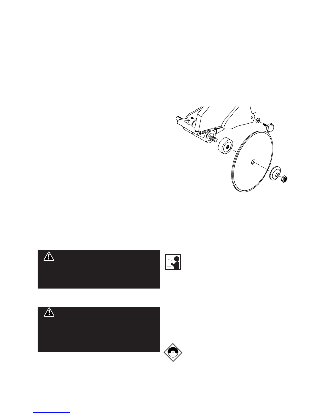
11.
Installing the blade,
install the blade with the
arrow pointing the same direction as the
rotation of the arbor shaft or the arrow on the
blade guard. Be sure to tighten the blade shaft
arbor nut with the wrench provided.
Be careful not to over tighten.
12. Check that the blade tracks near the center of
the channel in the main table, and that the table
moves freely from front to back.
13. Sometimes the material being cut is not
abrasive enough to expose new diamonds on
the blade. If the blade is not sharpened, it will
rub against the surface resulting in heat build
up in the core. To prevent this, it is necessary
to dress the blade. To dress the blade simply
cut something that is very abrasive such as a
piece of cement block. Indications that the
blade needs dressing includes:
• The diamond in the matrix appear shiny
because they are worn flat.
• The blade stops cutting or noticeably
slows down.
Blade dressing stones are available from your local Pearl
Warehouse.
14. Before using the saw fill the water tub enough
to submerge the water pump with clean water
only. Replenish as necessary and clean the
water tub frequently. Do not operate a wet
cutting blade without adequate water flow to
both sides of the blade. Never run the pump
dry.
15. When cutting, always hold the material firmly
lying flat, supported by the main table with one
edge resting against the main table backstop.
• Do not attempt to cut pieces too small to
safely hold down on the main table.
• Never use the side of the blade to cut or
grind with, only cut in a straight line.
• Keep all parts of your body away from the
blade and all other moving parts.
• Never touch or try to stop a moving blade
with your hand.
16. When cutting dry - always unplug the water
pump first.
Never run the pump dry.
• Do not use a wet cutting blade for dry
cutting. Select the proper dry cutting
blade for your application.
• Never make long continuous cuts with dry
cutting blades. To avoid heat build up,
allow the blade to cool, remove the tile
and allow the blade to run freely for a few
minutes.
IMPORTANT - If there is any tendency for the
saw to tip or move during certain operations,
such as when cutting large heavy tile; the saw
must be securely fastened to a supporting
table.
17. Make certain all adjusting knobs or locks are
tight and engaged in their detents and that
movable parts not intended to move during
operation are securely locked before making a
cut.
Be careful not to over tighten.
18. Before connecting the machine to a power
source check to see that the “On/Off” switch is
in the “off” position.
Not dressing the blade
frequently or setting the blade too high will cause
it to grab the tile possibly causing injury to the
operator and the saw. Setting the blade depth too
low will cause it to cut into the main table that
may result in injury.
WARNING!