Pearl Abrasive X10RS Owner's manual

Caution! Read Safety and Gene al Inst uctions ca efully befo e using saw fo the fi st time.
You should record the Serial Number of your
Tile Saw on this Owner’s/Operator’s Manual
and on the Warranty Card.
The Wa anty Ca d must be sent back with
all the equi ed pe tinent info mation fo the
wa anty to take effect.
Pat nts P nding
Ass mbl d in U.S.A.
P e a r l A b r a s i v e C o . 2 . 1 r a il S A W
REV. 1
serial number -
MODEL VXRS RAIL SAW
$+ !+ "

TABLE OF CONTENTS
' !!
'' !&" "!
''' !&"
'( !$
( " & !"
(' !
('' !"
(''' $ ! &
') !!
) "!! !!
)' !* " !!
)'' $!" !!
)''' !"
)'( !! $
)( !"!!!
)(' "!!!
)('' !!
)(''' !! !
)') !
)) + +!
))' $!
))'' $!"!
))''' !" !
))( $!&
))(' !! !
))('' #% $%#$
))(''' " ! #
))') $!
))) !!"

– 3 –
ii. GENERAL SAFETY RULES AND PRECAUTIONS
1. Know your power tool - rea owner’s/operator’s manual carefully. Learn its applications an limitations as
well as the specific potential hazar s unique to this tool.
2. Keep guar s in place - an in working or er.
3. Groun all tools - if tools are equippe with three prong plug, it shoul be plugge into a three-hole electrical
receptacle. If an a apter is use to accommo ate a two-prong receptacle, the a apter lug must be attache
to a known groun . Never remove the thir prong.
4. Remove wrenches - Form a habit of checking to see that a justing wrenches are remove from tool before
turning it “on”.
5. Keep work area clean. Cluttere areas an benches invite acci ents.
6. Do not use in angerous environment. Do not use power tools in amp or wet locations, or expose them to
rain. Keep work area well lighte . Do not use tool in the presence of flammable liqui s or gasses.
7. Keep chil ren an visitors away. All chil ren an visitors shoul be kept at a safe istance from work area.
8. Make workshop chil proof with pa locks, master switches or by removing starter keys.
9. Do not force tool. It will o the job better an be safer at the rate for which it was esigne .
10. Use right tool. Do not force tool or attachment to o a job for which it was not esigne .
11. Wear proper apparel. Do not wear loose clothing, gloves, neckties, rings, bracelets or other jewelry that may
get caught in moving parts. Non-slip footwear is recommen e . Wear protective hair covering to contain
long hair.
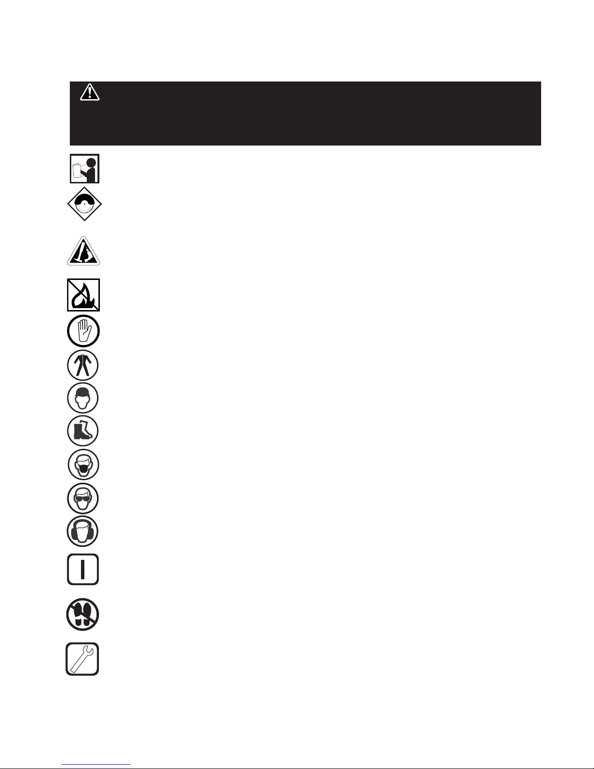
12. Always us saf ty glass s. Wear safety glasses (must comply with ANSI Z87.1) at all times. Every ay
eyeglasses only have impact resistant lenses; they are not safety glasses. Use face or ust mask if cutting
operation is usty, an ear protectors (plugs or muffs) uring exten e perio s of operation.
13. Do not overreach. Keep proper footing an balance at all times.
14. Maintain tools in top con ition. Keep tools sharp an clean for best an safest performance. Follow
instructions for lubricating an changing accessories. Inspect tool cor s perio ically an if amage , have
repaire by authorize service facility.
15. Disconnect tools. When not in use, before servicing, an when changing accessories, such as bla es, bits,
cutters.
16. Avoi acci ental starting. Make sure switch is in “off” position before plugging in power cor .
17. Use recommen e accessories only. Consult the owner’s manual for recommen e accessories. The use
of improper accessories may cause risk of injury to persons.
18. Never stan on tool. Serious injury coul occur if the tool is tippe or if the cutting tool is acci entally
contacte .
19. Check Damage Parts. Before further use of the tool, a guar or other part that is amage shoul be
carefully checke to ensure that it will operate properly an perform it’s inten e function. Check for
alignment of moving parts, bin ing of moving parts, breakage of parts, mounting, an any other con itions
that may affect it’s operation. A guar or part that is amage shoul be properly repaire or replace .
20. Never leave tool running unatten e . Turn power “off”. Do not leave tool until it comes to a complete stop.
Read all i structio s. As with all machi ery there are certai hazards i volved with
operatio a d use of the machi e. The followi g basic safety precautio s should be followed at all times to
reduce the risk of fire, electric shock a d serious perso al i jury to you or others. Keep these importa t
operati g i structio s with this product.
WARNING!

– 4 –
KEEP GUARD IN PLACE
DIAMOND BLADE
BLADE CUTTING DEPTH
ELECTRIC SWITCH OFF
ELECTRIC SWITCH ON
ELECTRICAL HAZARD
REMOVE TOOLS
PAY EXTREME
ATTENTION
REPAIRS TO BE DONE
MACHINE HAZARD
FLAMMABLE
READ INSTRUCTIONS
CAREFULLY
WARNING
FRAGILE
KEEP DRY
DO NOT STEP ON
WEAR HEARING
PROTECTION
WEAR EYE PROTECTION
WEAR BREATHING
PROTECTION
WEAR HARD HAT
WEAR PROTECTIVE
CLOTHING
WEAR SAFETY SHOES
WELL VENTILATED
NO NON-WORKING
PERSONNEL
21. Extension cor s. Make sure your extension cor is in goo con ition. When using an extension cor , be
sure to use one heavy enough to carry the current your pro uct will raw. An un ersize cor will cause a
rop in line voltage resulting in loss of power an overheating. If in oubt, use the next heavier gage. The
smaller the gage numbers the heavier the cor .
22. Do not abuse cor . Never carry tool by cor or pull it to isconnect from receptacle, Keep cor from heat,
oil, an sharp e ges.
23. Guar against electric shock. Prevent bo y contact with groun e surfaces. For example, pipes, ra iators,
ranges an refrigerator enclosures.
24. Out oor use extension cor s. When tool is use out oors, use only extension cor s inten e for use
out oors an so marke .
25. Stay alert. Watch what you are oing. Use common sense. Do not operate tool when you are tire .
26. Drugs, alcohol, me ication. Do not operate tool while un er the influence of rugs, alcohol or any
me ication.
27. Store i le tool. When not in use, tool shoul be store in a ry an locke place, out of reach of chil ren.
CALIFORNIA PROPOSITION 65: Sawi g a d drilli g ge erates dust. Excessive airbor e
particles may cause irritatio to eyes, ski a d respiratory tract. To avoid breathi g impairme t always employ
dust co trols a d protectio suitable to the material bei g saw or drilled i accorda ce with OSHA (29 CFR Part
1910.1). Diamo d blades improperly used are da gerous. Comply with ANSI Safety Code B7.1 a d OSHA coveri g
speed, safety guards, fla ges, mou ti g procedures, ge eral operati g rules, ha dli g, storage a d ge eral
machi e co ditio .
WARNING!

– 5 –
iii. HEALTH WARNINGS
Some ust are create by power san ing, sawing, grin ing, rilling, an cause other construction activities contains
chemicals known to cause cancer, birth efects or other repro uctive harm. Some examples of these chemicals are:
• L ad from l ad bas d paints,
• Crystallin silica from bricks and c m nt and oth r masonry products,
• Ars nic and chromium from ch mically-tr at d lumb r.
Your risk from these exposures varies, epen ing on how often you o this type of work. To re uce your exposure to
these chemicals: work in a well ventilate are, an work with approve safety equipment, such as those ust masks
that are specially esigne to filter out microscopic particles
iv. SPECIFICATIONS
The VX10RS professional rail saw is use for cutting floor tiles, paving stones, stairs, large -
size natural stones , an similar materials.
VX10RS RAIL SAW
MOTOR BLADE
CAPACITY
CUTTING
LENGTH
CUTTING
DEPTH WEIGHT
DIMENSIONS
8"-10" Bla e
5/8" arbor bla e
37" rip cut,
24" iagonal cut
2-5/8" 145 lbs. 33.1" L
x 18.7" W
x 12.7" H
1-1/2 HP
115 v, 60 Hz,
3,450 rpm
In uction motor

– 6 –
v. FEATURES
The VX10RS Stone Saws are esigne with water flow control in min . The water
pump, insi e the tray or as an option it can be use insi e a bucket, a water control
valve an splash guar s ensure proper water flow uring operation.
Pow rful 1-1/2HP
Dir ct Motor cuts
larg r mat rials
Rubb r Matt d
Cutting Tabl Sturdy Wh ls
for Easy Transport
Position Lock
Cutting H ad
Splash Guard
r duc s Wat r
Wast
Blad Capacity of
10" nhanc s
Cutting Capacity
R movabl Ext n-
sion Tabl adds
xtra workspac
10"

– 7 –
UNPACK
Open the container, carefully lift the saw frame han les
an place it on a flat, level working area. Be certain that
you have the following items before you iscar the
container:
Saw Water Pump
Fol -in Legs with Wheels Water Level Tube
10" Saw Bla e Owner’s Manual
Multiple Rip Gui e Drain Plug
Multiple Wrench Bucket
Proceed to the following section to complete
assembly of the saw.
ASSEMBLY & SET-UP
a. Remove the carton box cover from the
woo en frame.
b. Remove saw from the crate.
c. Loosen the lock knob on top of the cutting hea .
. Install the si e extension table, si e splash guar
an back splash guar .
e. Install the spring hol er on top of the sli ing rail
to hol the power cable an the water hose
f. Fill the tray with water before operating the saw.
1. FOLD-IN LEGS
a. Lifting up one si e of the saw, sli e in the legs
(with no wheels) to the front si e of the saw.
Lock the wing nut to tighten the legs in place.
b. Lift up the other si e of the saw an sli e in the
legs with the wheels. Lock the wing nut to
fasten the legs in place.
2. EASY TRANSPORT
a. Unlock the wing nut. Lift up the back si e of the
saw an sli e the legs with wheels,lock the
wing nut.
b. Go to the other si e of the saw an unlock the
wing nut. Lift up the other si e of the saw an
insert the legs, lock the wing nut. Using the legs
as han les, tilt the saw iagonally an roll the
saw on the wheels like a olley.
a. Loosen the knurle nuts securing the bla e
guar an remove the guar .
b. Loosen the cutting shaft nut (left-han threa );
while loosening the nut, block the cutting shaft
from turning.
c. Remove the bla e clamping flange. Check that
the contact area between the bla e hol er
assembly an the iamon saw bla e is clean.
. Install the saw bla e on the supporting flange,
ensuring the correct sense of rotation marke
by the arrow on the bla e.
e. Install the bla e clamping flange.
f. Retignten the cutting shaft nut. Block the
cutting shaft form turning while tightening
the nut.
g. Lightly turn the installe saw bla e by han an
check the bla e for true running.
h. Mount the bla e guar .
vi. UNPACK, ASSEMBLY & SET-UP
Knurle
Nuts
Figur 1
vii. SAW LEGS ASSEMBLY
viii. BLADE INSTALLATION
Setti g the blade too
low may damage the cutti g table a d if
set too high, the blade may grab the
material bei g cut, causi g damage a d
possibly i jury.
WARNING!

– 8 –
i . CUTTING HEAD
INSTALLATION
. SIDE TABLE & SPLASH GUARD
INSTALLATION
1. Sli e the motor into the bo y of the cutting hea
mainframe, hol ing the motor front (outer) ring
insert into the mainframe bracket.
2. Hol ing the cutting hea stea y, insert 4 bolts onto
the front en of the motor through the cutting hea
mainframe. Lock the bolts tight to hol the motor in
position.
3. Insert the inner flange onto the bla e shaft against
the motor’s front en .
4. Place the bla e onto the shaft making sure the
irectional arrows are pointing in the irection of the
shaft rotation. Secure in place with the outer flange
an bla e shaft nut.
5. Insert the main long bolt in the upright of the front
plate while hol ing the cutting hea mainframe, lock
it tight in position. Insert the secon long bolt into
the height a justment slot an lock it tight in
position. Place the tension spring into position for
height a justment. See figure 2.
1. Install the si e table an splash guar as shown in
figure 3 to the si e. Fasten the screws respectively
to the saw frame.
1. Remove the water pump from the box an check that
it is not amage .
2. Place the pump into the bracket at the right front
corner of the water tray along its si e so that the
water outlet is positione horizontally. Connect the
water hose from the bla e guar to the pump an
plug the power cor into the 3-prong receptacle.
3. Fill the water tray so that the water intake is fully
immerse .
4. Be sure to support the pump uring installation to
prevent pump failure or amage.
Figur 2
Figur 3
Figur 4
i. WATER PUMP INSTALLATION
Disco ect the pump
before attempti g to ha dle the pump.
Never operate pump without water i
the tray.
WARNING!

– 9 –
ii. THE RIP GUIDE
iii. OPERATING THE SAW
The MasterGui e is a two-piece assembly consisting
of a template base an a unique etachable ruler
gui e. This permits any cutting angle between 0°
an 45° , with 22° an 30° clearly esignate . The
ruler gui e also oubles as a measurement tool to
accurately measure slabs up to a foot in length.
The MasterGui e has a locking mechanism that
secures the ruler gui e firmly to the template base.
1. After you have ma e yourself familiar with the
components of you saw, the machine has been
properly set up, the bucket or water tray is fille with
water, an the electrical connection is establishe
accor ance with the relevant safety regulations, you
may now begin with the cutting operation.
2. Before you start operation open the water shut-off
valve.
3. During the operation, the user must stan in front
si e of the saw, hol ing the han le of the swivel-joint
cutting hea with his left han . The workpiece must
rest on the work table an shoul be presse tightly
against the si e an limit stops with the right han .
4. Always turn off the saw before you leave the machine
unatten e .
5. After the cutting operation is finishe , prevent
acci ental restarting of the saw by pushing the
emergency stop from the switch bracket an
unplugging the power cable.
A. CUTTING AT
CONSTANT DEPTH
When cutting at constant depth the cutting head
must be pulled against the workpiece.
• Before you start cutting, set the cutting hea at the
esire fixe cutting epth.
• Then use the han le to pull the cutting hea slowly
an uniformly along the gui e rail an across the
workpiece.
• Push the cutting hea fully back after you finishe
the cut.
B. PLUNGE CUTS
The handling of larger cutting depths can be
simplified using the plunge cutting method.
• In this case, the cutting hea will not be set to a fixe
position while performing the cut.
• As you have not fixe the saw at a efine epth,
the cutting hea is freely movable uring seesaw
operations.
• Hol the han le of the cutting hea with your left
han an move it to an fro across the workpiece
while lightly pressing the cutting hea ownwar s in
a iscontinuos movement.
Figur 5
Always lock the rip guide
prior to tra sporti g the saw.
WARNING!
MASTERGUIDE
Detachable Ruler
Template Base
iv. USING THE CUTTING TABLE
Figur 6

– 10 –
FEATURES
• The easily removable cutting table is covere with an
anti-ski rubber coating, which allows the material
being cut to sit still on the table while the cutting
hea is pulle through it.
• Simply line up the material being cut with the
appropriate pre-marke lines on the cutting table.
STEPS TO MAKE MITER CUTS
1. The bench saw is equippe with a hinge gui e rail
that allows the user to make accurate mitre cuts.
2. To pivot the gui e rail, lightyly loosen the palm grips
at both front si es of the saw.
3. Set the rail to the esire angle.
4. Firmly re-tighten the palm grips after setting the
gui e rail.
The recommen e cutting epth is 1/4" below the
cutting table surface. The cutting clearance has
been fixe from original esign.
For the most effective cutting and blade life always
use the recommended Pearl Abrasive Co. diamond
blades.
• The bla e shaft spee
of this saw is
exclusively esigne
for cutting with
iamon saw bla es.
The saw may only be
use for cutting natural an artificial stone
materials, o not cut woo or metal!
• The saw uses iamon saw bla es with iameters
up to 10". Saw bla es with larger iameters must
not be installe on the saw.
• Choose the correct type of saw bla e for the
material to be cut an the require cutting epth.
RECOMMENDATIONS
• It is recommen e that a 15 amp circuit be use
while operating this saw. This will prevent possible
power interruption or loss.
• Always plug saw as close as possible to the power
source while operating. This will allow you to
receive optimum electricity.
vi. CHOOSING THE
RIGHT BLADE
v. CUTTING DEPTH
BLADE DIAMETER CUTTING DEPTH
8 inch 1-1/2 inch
10 inch 2-5/8 inch
Setti g the blade too low
may damage the cutti g table a d if set too high,
the blade may grab the material bei g cut, causi g
damage a d possibly i jury.
WARNING!
To avoid perma e t motor
damage you must use this
correct exte sio cord.
Never use more tha o e
exte sio cord at a time.
Follow the chart for proper
size.
WARNING!
vii. ELECTRIC MOTOR
SPECIFICATIONS
HORSE POWER
VOLTS
AMPS
MOTOR RPM
CYCLE
PHASE
1-1/2 HP
115 volts
15 amp
3450 rpm
60 Hz
1
Black
Green Motor
Green
Wiring Box
Black
WhiteWhiteWhite
Overcurrent
Breaker
Switch
Power OutletforWater Pump
WIRE
GAUGE
No. 12
No. 10
No. 8
1-1/2 hp
115V
25'
50v
75'
LENGTH OF
CORD

DRY CUT BLADES
DO’S
• In a ition to the following, always follow wet
recommen ations.
• Use appropriate bla e for material being cut.
• Inspect segment bla es for segment cracking or loss.
• Do not use amage bla es.
• Use proper safety equipment when operating the
saw.
DONT’S
• In a ition to the following, always follow wet
recommen ations.
• Do not make long cuts with ry bla es--allow them to
air cool.
• Do not use the e ge or si e of bla e to cut or grin .
• Do not attempt to cut a ra ius or curve.
• Do not cut too eep or too fast into the material.
• Do not cut any material not recommen e by bla e
manufacturer.
WET CUT BLADES
DO’S
• Inspect bla es aily for cracks or uneven wear.
• Always use appropriate bla e for material being cut.
• Inspect arbor shaft for uneven wear before mounting
bla e.
• Always use bla es with the correct arbor shaft size.
• Ensure that bla e is mounte in the correct irection.
• Secure the bla e to the arbor with a wrench.
• Use proper safety equipment when operating the
saw.
• Perio ically check the bla e for cracks or bon
fatigue.
• Always have a continuous flow of water on both si es
of bla e.
DONT’S
• Do not operate the saw without safety guar s in
position.
• Do not operate the saw with bla es larger than 10".
• Do not cut ry with bla es marke "Use Wet".
• Do not excee manufacturer's recommen e
maximum RPM.
• Do not force bla e into material let bla e cut at its
own spee .
viii. THE RIGHT BLADE DOES THE RIGHT JOB
i . DO’S AND DONT’S FOR BLADES
– 11 –
CERAMIC EXTRA HARD PORCELAIN MARBLE GRANITE HARDSTONE STONE
TILE CERAMIC
For the most effective cutting an bla e life always use the recommen e Pearl Abrasive Co. bla e.
APPLICATION
PEARL
BLADE
SERIES
DTLB19 Series
GRT Series
SD Series
SH Series
SHD Series

. CARE AND MAINTENANCE
– 12 –
GENERAL RULES
• Always clean the machine before maintenance/repair.
• Before cleaning/maintenance/repair, the machine
must be switche off with the main power key.
STEPS TO FOLLOW WHEN CLEANING
a. Please o not use aggressive cleaners (i.e. containing
solvents). Do not use high-pressure water jets,
aggressive etergents or solutions an liqui s with a
temperature excee ing 86°F Use a fluff-free cloth
only.
b. Use a cloth which may be lightly moistene only for
removing ust an irt. Har packe irt can be
remove with a soft brush.
c. For the sake of safety, no water/cleaning liqui /vapor
may penetrate into the electric motor, connectors
/plugs, switches, etc. Therefore cover all apertures,
holes in the housing, connectors or plugs, etc. or
seal them with a hesive tape.
. Use a soft, low-pressure water jet an a brush to
rinse irt an incrustations away. Be particularly
careful when near hazar ous parts of the machine
(e.g. switch, motor). Clean the motor an switches
only by wiping with a moist cloth.
e. Do not "rinse" the bearings of the rive elements to
prevent them from running ry. The ball bearings of
the machine are permanently lubricate .
f. After cleaning, remove all covers an a hesive tape
All screws/nuts which you may have loosene must
be tightene again.
g. After wet cleaning, try the machine on a power outlet
which is equippe with a power breaker (i.e. fault
current circuit breaker). If the fault current circuit
breaker cuts the power supply, the machine must be
inspecte by an authorize ealer prior to use.
CLEANING
AFTER EVERY USE OF THE MACHINE:
• Remove irty water from container.
• Remove irt an mu from the bottom of the
container.
• Rinse the immersion pump with fresh water to
prevent water pump clogging from resi ual irt.
AFTER WET CLEANING AND BEFORE
USING THE MACHINE AGAIN:
• Connect the machine to an electric power outlet
equippe with a "GFCI” safety power breaker. If the
safety power breaker cuts off the electrical power
supply, o not try to operate the machine but have it
checke by an authorize ealer first.
BEFORE & AFTER A
PROLONGED TIME
BEFORE NOT USING THE MACHINE FOR A
PROLONGED PERIOD OF TIME:
• Clean an lubricate all movable parts. DO NOT
GREASE THE GUIDE RAILS.
AFTER NOT USING THE MACHINE FOR A
PROLONGED PERIOD OF TIME:
• Check that the legs are safely fixe .
• Check that all screw joints an nuts are fixe .
• Check that the roller table is in its gui es an that it
easily moves to an fro.
• With the saw bla e remove , switch on the motor for
an instant an switch it off again. If the motor oes
not run, have the machine inspecte by a qualifie
electrician.
• Check that the immersion pump works properly. Turn
on the cooling water tap an switch the machine on.
If the pump oes not give any water or only a little,
switch the machine off at once. Clean the pump, or
replace if necessary.
For your safety before
performi g a y mai te a ce o the saw, tur off
the power switch a d u plug the power cord.
WARNING!

– 13 –
TEMPERATURE CHANGES
AMBIENT TEMPERATURE
BELOW 37°F (WINTER)
• To prevent the water in the pump an cooling system
from freezing, remove the water after using the
machine or when there will be a long break. Make
sure that the cooling system is entirely raine so
that there is no water left insi e the pump, the
bearing house an water hose.
When the machine has not been use for a long perio of
time, har packe irt may begin to buil up insi e the
pump an block the pump wheel. If the machine is
activate with the immersion pump blocke , the electric
motor of the pump will be amage within a few minutes.
Please follow the steps liste below to clean the pump
before operating the saw.
1. Unscrew the pump filter.
2. Remove the immersion pump from the water
container.
3. Clean the immersion pump.
4. Loosen the fixing screws of the pump li .
5. Take the li off the pump (be careful not to amage
the gasket locate insi e with a sharp object)
6. Clean the pump li .
7. Remove all irt an incrustations from the pump
wheel.
8. Check whether the pump wheel can be easily turne .
9. Then reassemble the immersion pump correctly an
check whether it works properly.
i. WATER PUMP
MAINTENANCE
ii. ACCESSORIES
Part Nam
Angle Gui e
Part Numb r
V370060
Quantity
1
Part Nam
Table Extension
Part Numb r
V370014
Quantity
1

– 14 –
iii. REPLACEMENT PARTS LIST
1
2
3
4
5
6
7
8
9
10
11
61
65
66
54
12
13
14
15
16
17
18
19
20
21
22
64
60
A
1 Gui e Rail V370001
2 Ruler Gui e Bolt (set of 4)/M6X16 V370002
3 Supporting Post Lock Bolt/ M5X20 V370003
4 Ruler Gui e V370004
5 Angle A justment Lock Knob V370005
6 Front Rubber Cutting Table V370006
7 Center Lock Nut/ M10 V370007
8 Front Rubber Mat Cutting Table V370008
9 Drain Plug V370009
10 Main Metal Frame V370010
11 Water Pump V370011
12 Cable & Hose Spring Hanger V370012
13 Extension Table Lock Knob V370013
14 Si e Extension Table V370014
15 Si e Splash Guar V370015
16 Rear Rubber Cutting Table V370016
17 Splash Guar Wing Nut/M6 V370017
18 Back Water Splash Guar V370018
19 Cable & Hose Position Bracket V370019
20 Angle A justment Bolt/M6X20 V370020
21 Rear Support Post Plate V370021
22 Angle A justment Knob V370022
54 Angle A justment Screw/ Nut M6 V370055
60 Water Pump A apter V370061
61 Sli e-In Legs with Wheels (set of 2) V370062
64 Sli e-In Legs (set of 2) V370065
65 Rubber Wheel V370066
66 Bucket V370067
PART NAME PART NUMBER PART NAME PART NUMBER

– 15 –
23 Water Flow “Y” A apter V370023
24 Water Control Valve V370024
25 Bla e Guar Lock Knob V370025
26 Bla e Guar V370026
27 Water Splash Guar V370027
28 Bla e Lock Nut/M12 V370028
29 Outer Flange V370029
30 Motor Mounting Lock Bolt/M8X16 V370030
31 Motor Cutting Angle Screw/ Hex. Screw 250 M10 V370031
32 Han le Rubber Sleeve V370032
33 Motor Cutting Angle A justment Screw/Hex.Screw
235 M10 V370033
34 Tension Spring V370035
35 Cutting Hea Carrage Bracket V370036
36 Han le Bar V370037
37 Han le Rubber Sleeve V370038
38 Cutting Hea Position Bracket V370039
39 Motor Position Lock Knob V370040
40 Circuit Breaker V370041
41 Toggle Switch V370042
42 Switch Housing Control Panel V370043
43 Switch Housing Complete Set V370044
44 Cable Protective Rubber Sleeve V370045
45 A justment Gui e Wheels (1) V370046
46 Cutting Height A justment Lock Knob V370047
47 Lock Nut/ M10 V370048
48 Power Cable/ 14AWG V370049
49 1-1/2 HP Motor V370050
50 Motor Mounting Bracket V370051
51 Cutting Table Hea Travel Bumper V370052
52 Inner Flange V370053
53 Diamon Bla e V370054
55 A justment Gui e Wheels (set of 2) V370056
56 Rolling Wheels (3) V370057
57 Multiple Wrench V370058
PART NAME PART NUMBER PART NAME PART NUMBER
39
43
40 41
42
44
45
46
47
48
49
50
51
52
53
57
55
56
38
37
36
35
34
33
32
30
23
24
25
26
27
28 29
31
A

– 16 –
iv. TROUBLESHOOTING
PROBLEM POSSIBLE CAUSE SOLUTION
- Power cor not properly
fixe /plugge in.
-Power cor efective.
- Main power switch
efective.
- Loose electrical connection insi e
the electric system.
- Motor efective.
- Too much pressure exerte while
cutting.
- Incorrect specification for saw
bla e.
- Saw has a efective electric system.
- Power cor /extension cable too
long or cable still woun up insi e
cable rum.
- Power network is insufficient.
- Drive motor no longer runs at rate
spee (r.p.m.).
- The pump raws air.
- Filter clogge .
- Pump wheel of the immersion
pump blocke by irt.
- Poor tension in the bla e material.
- Saw bla e is amage or bent.
- Flange of the saw bla e is
amage . Shaft of the motor bent.
- Overheating of the saw bla e;
cooling water not sufficient.
- Check that the machine is properly
connecte to the power supply.
-Have the power cor checke ,
replace if necessary.
- Have the main power switch
checke an replace if necessary by
a qualifie electrician.
- Have the whole electric system of
the machine checke by a qualifie
electrician.
- Have the motor checke an
replace if necessary by a qualifie
technician.
- Exert less pressure when cutting.
- Use a saw bla e which correspon s
to the material being cut.
- Have the electric system of the saw
checke by a qualifie technician.
- Use a power cor /extension cable
of the rate length, use a cable
rum with cable fully exten e .
- Observe the electrical ratings of the
machine an connect it only to a
power network which complies with
these ratings.
- Have the motor checke by a
quilifie electrician an have it
replace if necessary.
- Fill the container with water.
- Clean the filter of the pump.
- Disassemble the immersion pump
an clean.
- Return the saw bla e to the
manufacturer.
- Have the saw bla e aligne /
flattene .
- Clean the receiving flange.
- Sol er the iamon segments of
the ol bla e onto another saw
bla e or use a new bla e.
- Replace the saw bla e flange.
- Replace the electric motor.
- Have the iamon segment
sol ere on the bla e again; ensure
optimum flow of cooling water.
MACHINE DOES NOT RUN WHEN
SWITCHED ON
MOTOR STOPS
(POWER CUT OUT)
POOR MACHINE PERFORMANCE
LITTLE POWER
INSUFFICIENT FLOW OF COOLING
WATER OR NO COOLING WATER
AT ALL
IRREGULAR RUN OF THE
SAW BLADE
SAW BLADE WOBBLES WHEN
RUNNING
DIAMOND SEGMENT BECOMES
LOOSE

– 17 –
PROBLEM POSSIBLE CAUSE SOLUTION
-Wrong type of saw bla e.
- Shaft of motor causes wobbling.
- Overheating.
- Saw bla e type is unsuitable for the
material being cut.
- Saw bla e ype is unsuitable for the
machine performance.
- Saw bla e too har .
- Diamon segments are blunt.
- Poor tension in the bla e material.
- Too much loa place on the saw
bla e.
- Diamon segments are blunt.
- The saw bla e has slippe on the
motor shaft when running.
- Saw bla e overheating ue to a lack
of cooling water.
- Lateral friction when cutting.
- Material is not being fe parallel to
the saw bla e
- Poor tension in the bla e material.
- Too much loa on the saw bla e.
-Use har er saw bla es.
- Have bearings of the motor or the
motor replace .
- Ensure optimum flow of cooling
water.
- Use appropriate type of saw bla e.
- Sharpen the iamon saw bla e.
- Return the saw bla e to the
manufacturer.
- Use a suitable saw bla e.
- Sharpen the saw bla e.
- The arbor of the saw bla e must be
fitte with an appropriate a ator
ring.
- Check the receiving flange an have
it replace if necessary.
- Ensure an optimum flow of cooling
water.
- The material fee is too high;
procee more slowly.
- Ensure that the irection of fee is
absolutely parallel to the saw bla e.
- A just the roller table or have it
a juste .
- Have the saw bla e tensione .
- The material fee is too high,
procee more slowly.
EXCESSIVE WEAR
APPEARANCE OF CUT
IS NOT OPTIMAL
THE CENTER HOLE IN THE SAW
BLADE HAS BECOME WIDER DUE
TO WEAR
SAW BLADE SHOWS BLOOMING
COLORS
GRINDING MARKS ON THE
SAW BLADE

– 18 –
v. HOW TO ORDER PARTS
Please have the following information rea y before calling:
• Serial Number of your Tile Saw
• Mo el Number of the Tile Saw
• When purchase an where
• Part Description
All parts liste may be or ere from your Local warehouses. If the part is not stocke locally, call our Corporate office an
ask for our Customer Service Department. For Technical Support call 1-800-969-5561. In Cana a call 1-800-387-0008.
There is a $25.00 minimum or er.
Return Policy: Return goo s for cre it or exchange on the basis of the following terms: (1) They must be current pro ucts;
(2) Items returne for replacement or refun shoul be in original cartons an must be accompanie by a packing slip with
the following information: Returne Goo s Authorization (RGA) number obtainable from Customer Service Department •
List of items returne • Reason(s) for return(s) • Copy of original invoice(s); (3) Freight charges must be assume by
sen er; (4) Returning goo s are subject to a 15% han ling charge to cover our cost of repacking an restocking. All Prices
are subject to change without notice.
Disclaimer: Pearl Abrasive Co. reserves the right to make changes or improvements on its pro ucts without incurring an
a itional obligation inclu ing any obligation to make correspon ing changes or improvements to pro ucts previously
manufacture or sol . Pearl reserves the right to iscontinue pro ucts at any time without notice.
All illustrations isplaye in this manual are the property of Pearl Abrasive Co. an shall not be uplicate or repro uce
without the express written consent of Pearl Abrasive Co.
vi. CUSTOMER SERVICE
After Sale Service
All customer service (technical questions, re-or er of parts, etc.) will be provi e by our company. All spare parts for after
sales service will be stocke an shippe from our warehouse. If requeste , we may arrange for our sales representatives
to hol a training class for pro uct knowle ge at ealer’s location.

– 19 –

Part No. VX10RS • 07/17
GEORGIA • USA
3950 STEVE EYNOLDS BLVD.,
NO C OSS, GEO GIA 30093
ONTARIO • CANADA
375-2 PIDO OAD
PETE BO OUGH, ONTA IO K9J-6X7
CORPORATE OFFICE: SO. CALIFORNIA • USA
4900 ZAMB ANO ST., COMME CE, CA 90040-0031
562-927-5561 • FAX 562-928-3857
Toll Free: 800-969-5561
www.pearlabrasive.co
This manual suits for next models
1
Table of contents
Other Pearl Abrasive Saw manuals

Pearl Abrasive
Pearl Abrasive VX141MSPROR Owner's manual

Pearl Abrasive
Pearl Abrasive PA-7PRO Owner's manual

Pearl Abrasive
Pearl Abrasive VX MSPRO VX141MSPRO Owner's manual

Pearl Abrasive
Pearl Abrasive VX10.2XLPRO User manual

Pearl Abrasive
Pearl Abrasive PA20HSP Owner's manual

Pearl Abrasive
Pearl Abrasive VX10RS User manual

Pearl Abrasive
Pearl Abrasive VX7.2XL Owner's manual

Pearl Abrasive
Pearl Abrasive PA-10 Owner's manual