PEERLESS Mounts PLA60-UNLP-GB Guide

Models: PLA60-UNLP-GB, PLA60-
UNLP-GS, PLAV60-UNLP-GB, PLAV60-
UNLP-GS
Installation and Assembly - Universal Articulating
SwivelArm for 37" - 60" Plasma Screens
3215 W. North Ave. • Melrose Park, IL 60160 • (800) 729-0307 or (708) 865-8870 • Fax: (708) 865-2941 • www.peerlessmounts.com
ISSUED: 11-20-06 SHEET #: 202-9179-2 12-05-06
Maximum UL Load Capacity:175 lb (79 kg)
This product is UL Listed. It must be
installed by a qualified professional
installer.
R

2 of 39 ISSUED: 11-20-06 SHEET #: 202-9179-2 12-05-06
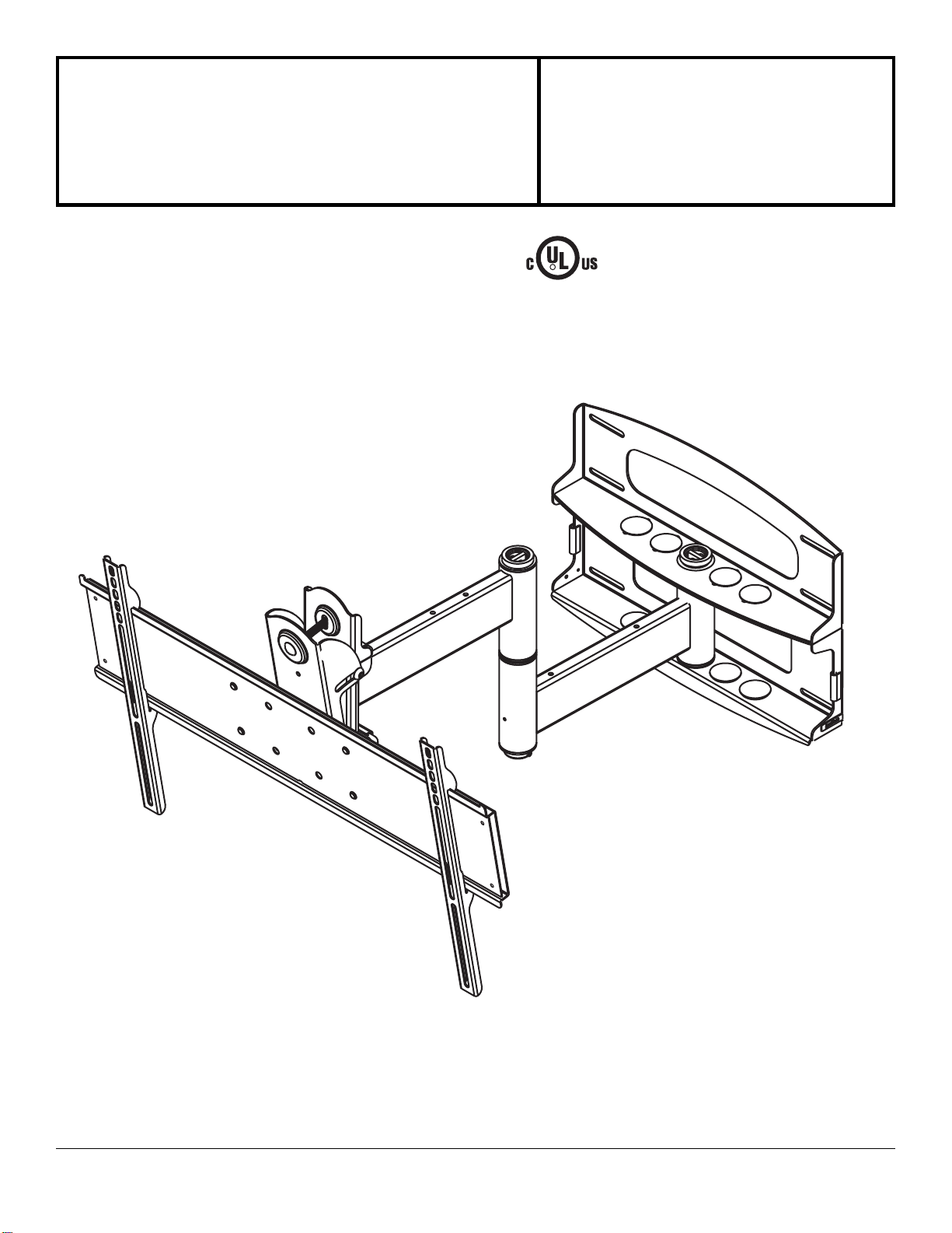
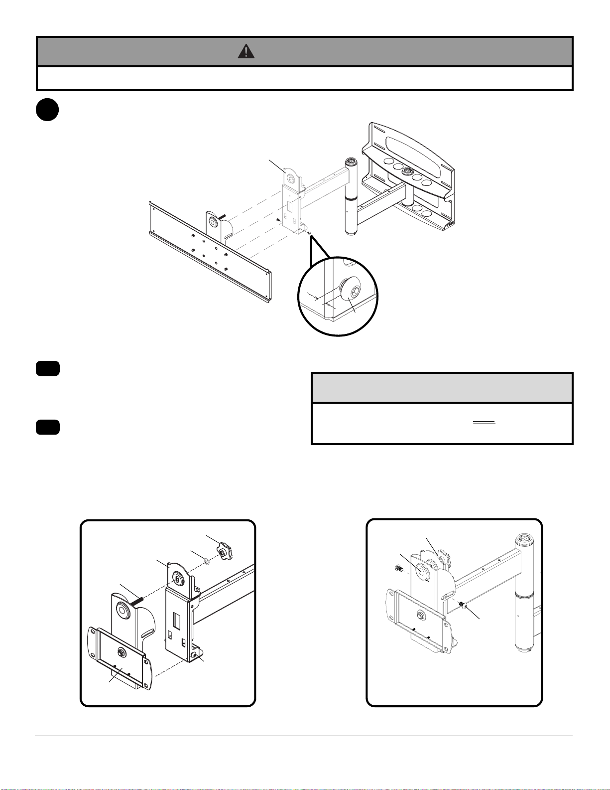
Read instruction sheet before you start installation and assembly.
Installations:
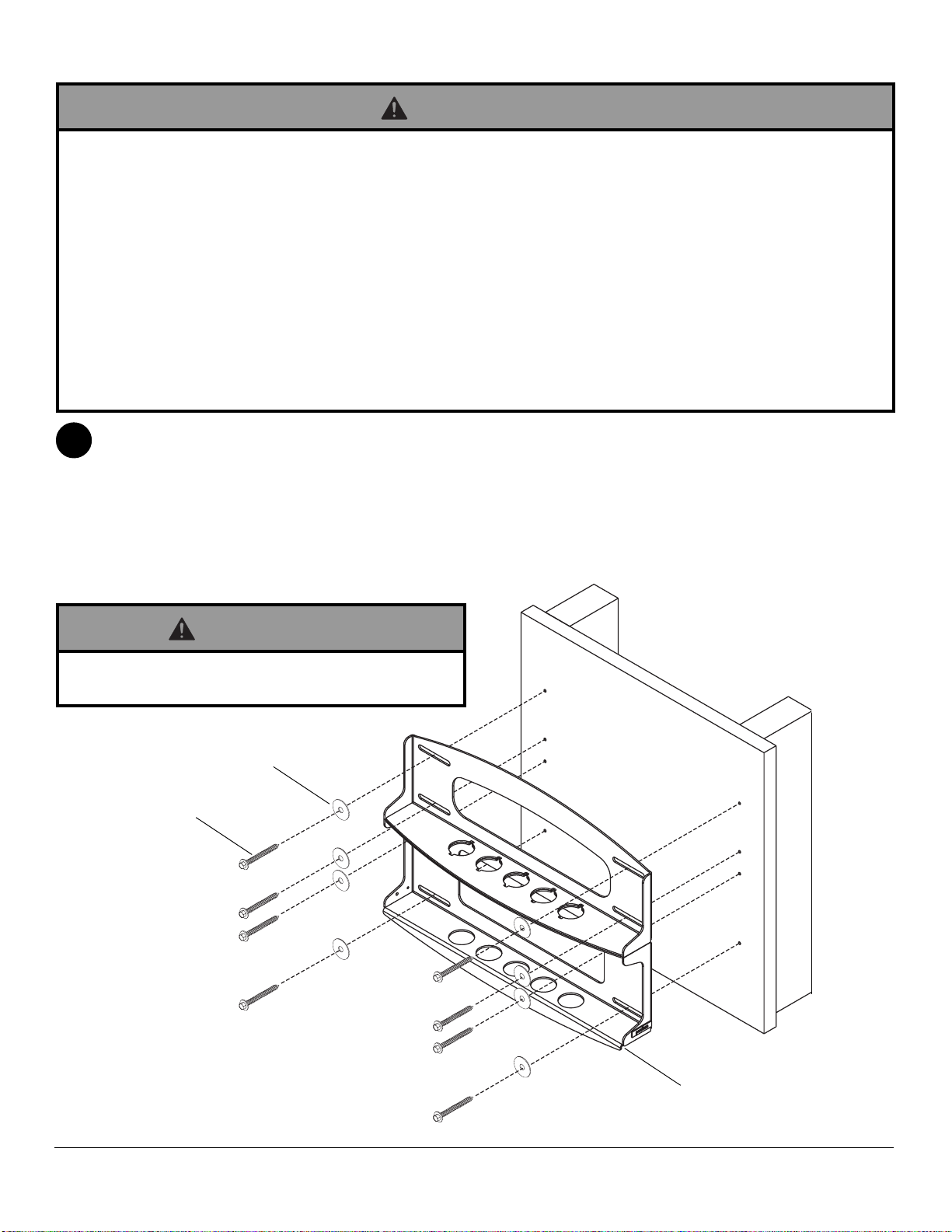
To Wood Stud Walls ...................................................................................................... page 6
To Concrete Walls .......................................................................................................... page 7
IMPORTANT! Turn to the appropriate page for your wall installation.
• DonotbegintoinstallyourPeerlessproductuntilyouhavereadandunderstoodtheinstructionsandwarnings
containedinthisInstallationSheet.Ifyouhaveanyquestionsregardinganyoftheinstructionsorwarnings,please
callPeerlesscustomercareat1-800-729-0307.
• Thisproduct should only be installed by a qualified professional.
• Makesure that the supporting surface will safely support the combined load of the equipment and all attached hard-
wareand components.
• Neverexceed the Maximum UL Load Capacity of 175 lb (79 kg).
• Do not attach directly to a metal stud wall. Use of a triple stud WSP wall plate is required for attachment to metal
studs (contact customer care). Metal stud installation is not UL evaluated.
• If mounting to wood wall studs, make sure that mounting screws are anchored into the center of the studs. Use of an
"edgeto edge" stud finder is highly recommended.
• Always use an assistant or mechanical lifting equipment to safely lift and position equipment.
• Tightenscrewsand nutsfirmly,butdo not overtighten. Overtightening can damage the items, greatlyreducingtheir
holdingpower.
WARNING
Tools Needed for Assembly
•studfinder ("edge to edge" stud finder is recommended)
•drill
•7/32" drill bit for wood studs
•5/16" masonry drill bit for concrete
•7/16"socketwrenchwithextension(recommended)
•level
•phillipsscrewdriver
WALLCONSTRUCTION ADDITIONAL HARDWARE REQUIRED
Wood Stud, Wood Beam none
Concrete none
Metal stud WSP716, WSP716-S, WSP724, or WSP724-S
Other or unsure? Contact Customer Care
IMPORTANT! Certain types of walls require additional mounting hardware...
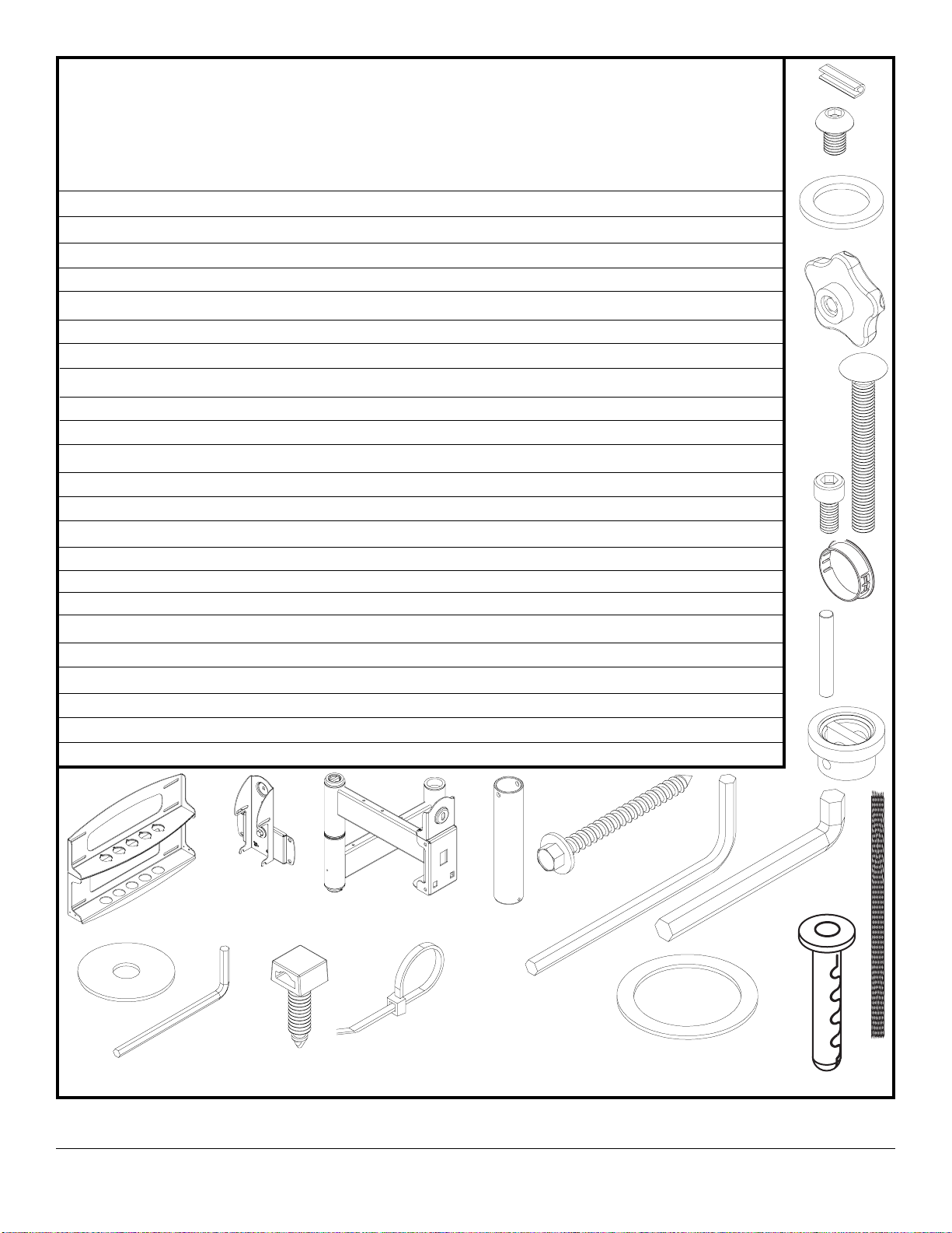
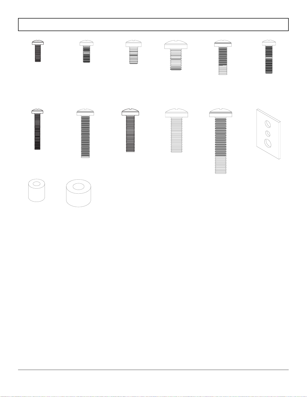
Accessories
•External Wall Plate (WSP716, WSP716-S, WSP724, WSP724-S)
(MetalStudnotevaluatedbyUL)

3 of 39 ISSUED: 11-20-06 SHEET #: 202-9179-2 12-05-06
DESCRIPTION QTY. PART# PART# PART# PART#
Awallplate 1 201-P1040 201-C4040 201-P1040 201-C4040
Btilt-roll assembly 1 201-P1093 201-C4093 201-P1048 201-C4048
Carmassembly 1 201-P1072 201-C4072 201-P1049 201-C4049
Dwallsupport arm axle 1 201-1041 201-1041 201-1041 201-1041
Evinyltrim 3 600-1012 600-1012 600-1012 600-1012
FM10 x 1.5 x 15 mm screw bolt 8 520-9262 520-9262 520-9262 520-9262
G.505 x .75 x .062" nylon washer 1 540-1074 540-1074 540-1074 540-1074
Htilt adjustment knob 1 560-0108 560-0108 560-0108 560-0108
Icarriage bolt 3/8"-16 x 3.25" 1 520-1315 520-1315 520-1315 520-1315
J1.525 x 2 x .062" delrin washer 2 540-1070 540-1070 540-1070 540-1070
K#8-32 x .375" socket cap screw 1 520-1210 520-1210 520-1210 520-1210
Lplastic finishing cap 8 590-1123 590-1123 590-1123 590-1123
Mholdingpin 1 580-1166 580-1166 580-1166 580-1166
Nretainerplug 1 590-1007 590-1007 590-1007 590-1007
O5/16 x 3" wood screw 8 520-1243 520-1243 520-1243 520-1243
P.250 x 1 x .068" washer 8 540-1063 540-1063 540-1063 540-1063
Q9/64"allenwrench 1 560-9728 560-9728 560-9728 560-9728
Rcablemanagementclips 4 590-1166 590-1166 590-1166 590-1166
Scable tie 4 590-1168 590-1168 590-1168 590-1168
T36"polyestermeshsleeve 1 600-1015 600-1015 600-1015 600-1015
U6 mm allen wrench 1 560-9716 560-9716 560-9716 560-9716
V10mmallenwrench 1 n/a n/a 560-9727 560-9727
Wanchor 8 590-1025 590-1025 590-1025 590-1025
E
F
D
Wall Mount Parts List
K
M
S
T
CA
H
B
N
L
Q
Some parts may appear slightly different than illustrated.
I
Before you start make sure all parts listed are included with your product.
O
P
UV
G
J
PLA60-UNLP-GB
PLA60-UNLP-GS PLAV60-UNLP-GB PLAV60-UNLP-GS
W
R

4 of 39 ISSUED: 11-20-06 SHEET #: 202-9179-2 12-05-06
DD
CCBBAA
Before you begin, make sure all parts shown are included with your product.
PLA 60-UNLP-GB PLA 60-UNLP-GS
PLAV 60-UNLP-GB PLAV 60-UNLP-GS
Description Qty Part # Part #
AA adapter bracket 1 201-P1110 201-C4110
BB shallow adapter bracket 2 200-P1754 200-C4755
CC deep adapter bracket 2 200-P1750 200-C4751
DD allen wrench 1 560-0072 560-0072
Adapter Bracket Parts List

5 of 39 ISSUED: 11-20-06 SHEET #: 202-9179-2 12-05-06
M6 x 20 mm (4)
520-9402
M6 x 30 mm (4)
510-9109 multi-washer(6)
580-1036
M8 x 16 mm (6)
520-9257
M8 x 40 mm (4)
520-1136
M4 x 12 mm (6)
504-9013
Phillips Adapter Bracket Fasteners
M4 x 25 mm (4)
504-1015
M5 x 12 mm (4)
520-1027 M5 x 25 mm (4)
520-9543
M6 x 12 mm (4)
520-1128
M6 x 25 mm (4)
520-1208
I.D. 5.6 mm (4)
540-1057
M8 x 25 mm (4)
520-1031
I.D. 8.7 mm (4)
540-1059

6 of 39 ISSUED: 11-20-06 SHEET #: 202-9179-2 12-05-06
• Installermust verify that the supporting surface will safely support the combined load of the equipmentandallattached
hardwareandcomponents.
• Tightenwood screws so that wall plate is firmly attached, but donotovertighten. Overtightening can damage the
screws,greatly reducing their holdingpower.
• Never tighten in excess of 80 in. • lb (9 N.M.).
• Do not attach directly to a metal stud wall. Use of a triple stud WSP wall plate is required for attachment to metal
studs (contact customer care). Metal stud installation is not UL evaluated.
• Make sure that mounting screws are anchored into the center of the stud. The use of an "edge to edge" stud finder is
highlyrecommended.
• Hardwareprovided is for attachment of mount throughstandardthickness drywall or plaster into woodstuds.Installers
areresponsible to providehardwarefor other types ofmounting situations.
• Neverexceed the Maximum UL Load Capacity of 175 lb (79 kg).
1
WARNING
Installation to Wood Stud Wall
Wall plate (A) can be mounted to two studs that are 16" apart. Use a stud finder to locate the edges of the
studs. Use of an edge-to-edge stud finder is highly recommended. Based on their edges, draw a vertical line
down each stud’s center. Place wall plate on wall as a template. The top mounting slots should be located .36"
abovethe desired screen center for PLA 60-UNLP-GB and PLA 60-UNLP-GS, and .43" below the desired screen
centerfor PLAV 60-UNLP-GB and PLAV 60-UNLP-GS. Level plate, and mark thecenter of the eight mounting
holes. Make sure that the mounting holes are on the stud centerlines. Drill eight 7/32" dia. holes 3" deep. Make
sure that the wall plate is level, secure it using eight 5/16 x 3" wood screws (O) and washers (P).
Skip to step 2 on page 8.
A
O
P
• Never mount this product to metal studs without the
requiredaccessory.
WARNING

7 of 39 ISSUED: 11-20-06 SHEET #: 202-9179-2 12-05-06
IMPORTANT!Concretemustbe 2000 psi density
minimum.
Use wall plate (A), making sure that it is level, as a
template to mark holes. The top mounting slots
shouldbe located.36" abovethe desired screen
centerforPLA60-UNLP-GBandPLA60-UNLP-GS
and .43" below the desired screen center for PLAV
60-UNLP-GB,PLAV60-UNLP-GS.Usethemasonry
bit to drill 5/16" (8 mm) dia. holes to a minimum depth
of 3" (76 mm). Insert anchors (W) in holes flush with
wallas shown(right).Place wallplate(A) overan-
chors and secure with 5/16 x 3" wood screws (O) and
washers(P).
• Concrete must be 2000 psi density minimum. Lighter density concrete may not hold concrete anchor.
• Make sure that the supporting surface will safely support the combined load of the equipment and all attached
hardwareandcomponents.
• Neverexceed the Maximum UL Load Capacity of 175 lb (79 kg).
• Never mount this product to metal studs.
WARNING
• Always attach concrete expansion anchors directly to
load-bearingconcrete.
• Neverattach concrete expansion anchors toconcrete
coveredwith plaster, drywall,or other finishing mate-
rial.If mounting to concrete surfaces covered witha
finishingsurface isunavoidable,the finishing surface
mustbe counterbored as shown below. If plaster/
drywall is thicker than 5/8", custom fasteners must be
supplied by installer.
WARNING
• Tighten wood screws so that wall plate is firmly
attached,but do notovertighten. Overtightening can
damagescrews, greatly reducingtheirholding power.
• Never tighten in excess of 80 in • lb (9 N.M.).
WARNING
1
Installation to Concrete Wall
A
OP
W
concrete
surface
1
3
2
Drill hole(s) and insert anchor(s) (W)
mounting
plate
Place plate over anchor(s) (W) and secure with screw(s)(O)
Tighten all fasteners
W
W
INCORRECT CORRECT
CUTAWAYVIEW
mounting
plate
plaster/
drywall
concrete mounting
plate concrete
plaster/
drywall

8 of 39 ISSUED: 11-20-06 SHEET #: 202-9179-2 12-05-06
Snap four cable management clips(R)into top or bottom of arm assembly(C)as shown.Cable ties (S) are used
withclips for cord management.
Slide one mesh sleeve (T) over each cable. Use cable ties (S) to tighten mesh sleeves to cables.
R
S
C
3
T
3-1
KD
N
J
D
M
J
C
DETAIL 3
A
Note: There are five mounting positions. The
center position is shown (right). Slidewasher (J)
over wall support arm axle (D). Next, insert plastic
cap (N) into axle. Then, insert holding pin (M) into
axle. See detail 1.
Note: Fit of axle (D) into wall plate (A) and arm
assembly (C) will be tight. Gently tap into place
with a hammer if necessary.
2
2-1
Insert socket cap screw (K) into hole at bottom of
wall support arm axle (D) as shown in detail 3.
Tightenscrew using 9/64" allen wrench(Q).
Place arm assembly (C) with washer (J) into wall
plate (A). Insert axle assembly shown in detail 1
throughwall plate (A), arm assembly (C),and
washer (J). Lock axle in place by aligning holding
pin (M) with notches shown in detail 2.
2-2
DETAIL 1
NOTCH
DETAIL 2
• If you are uncertain that product is properly installed, call customer care.
WARNING

9 of 39 ISSUED: 11-20-06 SHEET #: 202-9179-2 12-05-06
B
I
F
Insert and tape carriage bolt (I) into top hole of pitch-roll assembly (B).Attach tilt-roll assembly to adapter
bracket (AA) with four M10 socket screws (F). Tighten screws using 6 mm allen wrench (U).
• Donot overtightenscrews! Overtighteningmay hinder
rolloption.
CAUTION
4
5
Attach two pieces of vinyl trim (E) to wall plate (A). Next, attach one piece of vinyl trim to bottom of swivel box on arm
assembly(C).
4-1 Insertonefinishingcap(L)intoeachunusedholeof wall plate (A).
LA
E
SWIVELBOX
C
AA

10 of 39 ISSUED: 11-20-06 SHEET #: 202-9179-2 12-05-06
Insert two M10 screws (F) into swivel box on arm assembly (C) as shown. Leave approx. 1/4" of exposed thread.
.25"
F
• Use an assistant or mechanical lifting equipment to safely lift and position the plasmaTV.
WARNING
• After tilt is adjusted, all fasteners must be tightened.
Failure to do so will result in damage to the mount.
CAUTION
6
6-1
6-2
fig 6.1 fig 6.2
SWIVELBOX
Hook tilt-roll assembly (B) onto M10 screws (F).
Insert carriage bolt (I) into slot of swivel box as
shown in figure 6.1. Install nylon washer (G) and tilt
adjustmentknob (H).
Install remaining two M10 screws (F) as shown in
figure6.2. HAND TIGHTENallfour M10 screwsto
allowfor tilt adjustment. Removetape from carriage
bolt (I). For tilt adjustment, push back on the top of
plasma to relieve pressure on knob.Adjust tilt to
desired position and tighten tilt adjustment knob (H),
then securely tighten all four M10 screws (F) using 6
mmallen wrench (U).
I
BF
H
G
SWIVELBOX
H
F
I
C
Adapter bracket not shown for clarity. Adapter bracket not shown for clarity.

11 of 39 ISSUED: 11-20-06 SHEET #: 202-9179-2 12-05-06
Note: "X"dimensions should be equal.
• Tightenscrews so adapter brackets are firmly
attached. Do not tighten with excessive force.
Overtighteningcan cause stress damage to screws,
greatlyreducing their holding powerandpossibly
causingscrew heads to become detached. Tighten to
40 in. • lb (4.5 N.M.) maximum torque.
WARNING
Installing Adapter Brackets
Refer to Screen Compatibility Chart to determine the proper fasteners to use.
To prevent scratching the screen, set a cloth on a flat, level surface that will support the weight of the screen. Place
screen face side down. If screen has knobs on the back, remove them to allow the adapter brackets to be attached.
Place adapter brackets (BB or CC) on back of screen, align to holes, and center on back of screen as shown in figure
7.1.Attach the adapter brackets to the back of the screen using the appropriate combination of screws, multi-wash-
ers, and spacers as shown in figure 7.3.
Note: Top and bottom holes must always be used.
Verify that all holes are properly aligned,andthentighten screws using a phillipsscrewdriver.
• If screws don't get three complete turns in the screen
inserts or if screws bottom out and bracket is still not
tightly secured, damage may occur to screen or
productmay fail.
WARNING
MEDIUMHOLEFORM5SCREWS
SMALLHOLEFORM4SCREWS
LARGEHOLEFORM6SCREWS
fig. 7.2
BB
or
CC
CENTERBRACKETS
VERTICALLYONBACKOF
SCREEN
X
X
fig 7.1
Notes:
• Thenumber of fastenersused will vary,
dependingupon the type of screen.
• Multi-washers and spacers may not be
used,depending upon the type of screen.
• Use the corresponding hole in the multi-
washer that matches your screw size as
showninfigure 7.2.
SCREWS
SPACERS
BB or CC
fig 7.3
MULTI-
WASHER
MULTI-WASHER
7

12 of 39 ISSUED: 11-20-06 SHEET #: 202-9179-2 12-05-06
Mounting and Removing Flat Panel Screen
Referto mount instruction sheet for attachment of adapter bracket to mount.
Hook adapter brackets (BB or CC) onto adapter bracket (AA), then slowly swing screen in as shown. Turnscrews
clockwiseat least six timesto prevent screen frombeingremoved as shown indetail4. Tighten using allenwrench(DD).
Screen can be adjusted horizontally if desired.
Note: To lock the screen down, tighten screws to adapter bracket as shown in detail 4.
Toremove screenfrommount,loosenscrews, swingscreenaway frommount,andliftscreenoffofmount.
8
AA
BB or CC
DETAIL 4
SCREWS
AA
BB
or
CC
• Always use an assistant or mechanical lifting equipment to safely lift and position the plasma television.
WARNING

13 of 39 ISSUED: 11-20-06 SHEET #: 202-9179-2 12-05-06
Position of screen may be adjusted vertically up to
.79" in each direction by doing the following:
• To lower screen, turn socket screw shown in figure
10.1 clockwise with 10 mm allen wrench (V).
• To raise screen, turn socket screw shown in figure
10.1 counterclockwise with 10 mm allen wrench (V).
If it is too difficult to adjust roll of plasma, loosen
screws shown in figure 9.1 using a phillips screw-
driver.
IMPORTANT! Do not loosen ortightenscrews
morethan 1/8 turn.
Depending on the specific size & weight of the plasma,
articulatingswing arm may be angled at different
positions, causing plasma to appear to lean sideways
atdifferent articulating positions. Tilt-roll assembly (B)
allows plasma to be manually adjusted, so plasma can
be horizontal at all positions.To adjust, gently rotate
plasma by hand to desired position.
FOR PLAV 60 ONLY:
99-1
ARTICULATINGARM
PLASMA
10
SOCKET
SCREW
fig 10.1
ROLL
ADJUSTMENT
SCREWS
fig 9.1
©2006PeerlessIndustries, Inc. Allrights reserved.
Peerlessisaregisteredtrademark ofPeerless Industries,Inc.
Allotherbrand andproductnames are trademarksorregistered trademarksoftheir respectiveowners.

14 of 39 ISSUED: 11-20-06 SHEET #: 202-9179-2 12-05-06
Modèles :
PLA60-UNLP-GB, PLA60-UNLP-GS,
PLAV60-UNLP-GB, PLAV60-UNLP-GS
Installation et montage - Support mural articulé
universel pour écrans plasma de 37 à 60 po
3215 W. North Ave. • Melrose Park, IL 60160 • (800) 729-0307 or (708) 865-8870 • Fax: (708) 865-2941 • www.peerlessmounts.com
Capacité de charge maximale préconisée
par UL :175 lb (79 kg)
R
Ce produit est homologué UL. Il
doit être installé par uninstallateur
professionnel qualifié.

15 of 39 ISSUED: 11-20-06 SHEET #: 202-9179-2 12-05-06
• Ne commencez pas à installer votre produit Peerless avant d’avoir lu et assimilé les instructions et les avertissements
contenus dans cette fiche d’installation. Pour toute question concernant les instructions ou les avertissements,
veuillezappeler le serviceàla clientèle dePeerlessau 1-800-729-0307.
• Ceproduit doit être installéuniquement par un professionnelqualifié.
• Assurez-vousque la surface de support puisse soutenir sans danger la charge totale del’équipementainsique des
pièces et composants qui y sont attachés.
• Ne dépassez jamais la capacité de charge maximum de 175 lb (79 kg) établie par l’UL.
• Ne pas monter directement sur un mur à montants métalliques. Il est nécessaire d’utiliser une plaque murale WSP
afinde fixer le support à des montantsmétalliques(veuillez vous adresser au service à la clientèle). L’installation sur
montantsmétalliques n’a pas été évaluée par l’UL.
• Si vous l’installez sur un mur à montants en bois, assurez-vous que les vis de montage sont ancrées au centre des
montants.L’utilisation d’un localisateur de montants« bord àbord »estfortement recommandée.
• Pourlever et positionner l’équipement entoutesécurité, faites-vous toujours aider paruneautre personne ou utilisez
undispositif delevagemécanique.
• Serrez fermement les vis et les écrous, mais sans excès. Un serrage excessif peutendommager les composants et
enréduire considérablement la capacitédesupport.
Installation :
À des murs à montants en bois .................................................................................. page 19
À des murs en béton.................................................................................................... page 20
TYPEDEMUR PIÈCESDEFIXATION SUPPLÉMENTAIRES REQUISES
Montant ou poutre en bois aucune
Béton aucune
Montant métallique WSP716, WSP716-S, WSP724, WSP724-S
Autre surface ou incertain ? Communiquez avec le service clientèle
Lire la feuille d’instructions avant de commencer l’installation et le montage.
AVERTISSEMENT
IMPORTANT! Certains types de murs nécessitent des pièces de fixation supplémentaires..
Outils nécessaires au montage
•localisateur de montants (un localisateur de montants « bord à bord » est recommandé.)
•perceuse
•foret de 7/32 po pour montants en bois
•foretàmaçonnerie de 5/16 po pour béton
•cléàdouillede7/16poavec extension (recommandé)
•niveau
•tournevisPhillips
Accessoires
•Plaquemurale extérieure (WSP716, WSP716-S, WSP724, WSP724-S)
(Le montant métallique n’a pas été évalué par l’UL)
IMPORTANT ! Reportez-vous à la page correspondant au type de mur choisi pour l’installation

16 of 39 ISSUED: 11-20-06 SHEET #: 202-9179-2 12-05-06
DESCRIPTION Qté Pièce nº Pièce nº Pièce nº Pièce nº
Aplaquemurale 1 201-P1040 201-C4040 201-P1040 201-C4040
B support inclinable et rotatif 1 201-P1093 201-C4093 201-P1048 201-C4048
Cbrasarticulé 1 201-P1072 201-C4072 201-P1049 201-C4049
Daxedu support mural 1 201-1041 201-1041 201-1041 201-1041
Ebordureenvinyle 3 600-1012 600-1012 600-1012 600-1012
Fboulon à vis M10 x 1,5 x 15 mm 8 520-9262 520-9262 520-9262 520-9262
Grondelle 0,505 x .75 x 0,062 po 1 540-1074 540-1074 540-1074 540-1074
Hmolette 1 560-0108 560-0108 560-0108 560-0108
Iboulon 3/8 -16 x 3,25 po 1 520-1315 520-1315 520-1315 520-1315
Jrondelle 1,525 x 2 x 0,062 po 2 540-1070 540-1070 540-1070 540-1070
Kvis d’assemblage à tête creuse 1 520-1210 520-1210 520-1210 520-1210
Lemboutdefinition enplastique 8 590-1123 590-1123 590-1123 590-1123
Mtige de fixation 1 580-1166 580-1166 580-1166 580-1166
Nbouchondesûreté 1 590-1007 590-1007 590-1007 590-1007
Ovis à bois de 5/16 x 3 po 8 520-1243 520-1243 520-1243 520-1243
Prondelle de 0,250 x 1 x 0,068 po 8 540-1063 540-1063 540-1063 540-1063
Qcléhexagonale de 9/64 po 1 560-9728 560-9728 560-9728 560-9728
Rserre-câble 4 590-1166 590-1166 590-1166 590-1166
Sattache de câble 4 590-1168 590-1168 590-1168 590-1168
Tenveloppeenmaillepolyester 1 600-1015 600-1015 600-1015 600-1015
Uclé hexagonale de 6 mm 1 560-9716 560-9716 560-9716 560-9716
Vcléhexagonale de 10 mm 1 n/a n/a 560-9727 560-9727
Wchevilled’ancragepourbéton 8 590-1025 590-1025 590-1025 590-1025
E
F
D
Liste des pièces du support mural
K
M
S
T
C
A
H
BJ NRL
Q
Certaines pièces peuvent différer légèrement de l’illustration.
G
I
Avant de commencer, veuillez vous assurer que toutes les pièces énumérées sont incluses.
OPUV
PLA60-UNLP-GB
PLA60-UNLP-GS PLAV60-UNLP-GB
PLAV60-UNLP-GS
W

17 of 39 ISSUED: 11-20-06 SHEET #: 202-9179-2 12-05-06
PLA 60-UNLP-GB PLA 60-UNLP-GS
PLAV 60-UNLP-GB PLAV 60-UNLP-GS
Description Qté Pièce nº Pièce nº
AA support adaptateur 1 201-P1110 201-C4110
BB support adaptateur peu profond 2 200-P1754 200-C4755
CC support adaptateur profond 2 200-P1750 200-C4751
DD clé hexagonale 1 560-0072 560-0072
Avant de commencer, veillez à ce que toutes les pièces énumérées
Liste des pièces
DD
CC
BB
AA

18 of 39 ISSUED: 11-20-06 SHEET #: 202-9179-2 12-05-06
M6 x 20 mm (4)
520-9402
M6 x 30 mm (4)
510-9109 rondelle tout
usage (6)
580-1036
M8 x 16 mm (6)
520-9257
M8 x 40 mm (4)
520-1136
M4 x 12 mm (6)
504-9013
Fixations Phillips du support adaptateur
M4 x 25 mm (4)
504-1015
M5 x 12 mm (4)
520-1027 M5 x 25 mm (4)
520-9543
M6 x 12 mm (4)
520-1128
M6 x 25 mm (4)
520-1208
I.D. 5.6 mm (4)
540-1057
M8 x 25 mm (4)
520-1031
I.D. 8.7 mm (4)
540-1059

19 of 39 ISSUED: 11-20-06 SHEET #: 202-9179-2 12-05-06
1
AVERTISSEMENT
La plaque murale (A) peut être installée à deux montants espacés de 16 po. Repérez le bord des montants à
l’aide d’un localisateur de montants. L’utilisation d’un localisateur de montants « bord à bord » est fortement
recommandée.Après avoir repéré les bords, tracez une ligne verticale le long ducentrede chaque montant.
Posez la plaque murale sur le mur et utilisez-la comme gabarit. Les fentes de montage supérieures doivent être
situées à 0,36 po au-dessus de l’endroit souhaité pour le centre de l’écran pour les modèles PLA 60-UNLP-GB,
PLA60-UNLP-GS et à 0,43 po sous l’endroit souhaité pour le centre de l’écran pour les modèles PLAV60-UNLP-
GB et PLAV60-UNLP-GS. Mettez la plaque à niveau et marquez le centre des huit trous de fixation. Veillez à ce
que les trous de fixation soient sur la ligne médiane du montant. Percez huit trous de 7/32 po de dia. et de 3 po
de profondeur Veillez à ce que la plaque murale soit de niveau et fixez-la à l’aide de huit vis à bois de 5/16 x 3 po
(O) et des rondelles (P).
.Passez à l’étape 2 à la page 21
A
O
P
Installation sur des murs à montants en bois
• L’installateurdoit s’assurer que la surface de support puisse soutenir sans danger la charge totalede l’équipement
ainsi que des pièces et composants qui y sont attachés.
• Serrez fermement les vis à bois pour que la plaque murale tienne solidement en place, mais sans excès. Un serrage
excessifpeut endommager les viseten réduire considérablement le pouvoirdemaintien.
• Ne serrez jamais à plus de 80 po-lb (9 Nm).
•Ne pas monter directement sur un mur à montants métalliques. Il est nécessaire d’utiliser une plaque murale WSP
afin de fixer le support à des montants métalliques (veuillez vous adresser au service à la clientèle). L’installation
sur montants métalliques n’a pas été évaluée par l’UL.
• Assurez-vous que les vis de montage sont fixées au centre des montants. L’utilisation d’un localisateur de montants
"bordà bord" est fortementrecommandée.
• Lespièces de fixations fournies sont prévues pour une installation du support sur des montants enbois à travers une
cloison sèche ou du plâtre d’épaisseur standard. Il est de la responsabilité de l’installateur de fournir les pièces de
fixationrequises pour tout autre type d’installation.
• Ne dépassez jamais la capacité de charge maximum de 175 lb (79 kg) établie par l’UL.
AVERTISSEMENT
• N’installez jamais ce produit sur des montants
métalliques sans les accessoires requis.

20 of 39 ISSUED: 11-20-06 SHEET #: 202-9179-2 12-05-06
IMPORTANT ! Le béton doit avoir une densité minimale de
2 000 psi.
.
• Le béton doit avoir une densité minimale de 2 000 psi. Du béton de moindre densité risque de ne pas soutenir la cheville
pour béton.
• Assurez-vous que la surface de support puisse soutenir sans danger la charge totale de l’équipement ainsi que des
pièces et composants qui y sont attachés.
• Ne dépassez jamais la capacité de charge maximum de 175 lb (79 kg) établie par l’UL.
• N’installez jamais ce produit sur des montants métalliques.
AVERTISSEMENT
• Fixez toujours des chevilles àexpansion directement
surle béton porteur.
• Ne fixez jamais des chevilles à expansion pour béton
àdubéton recouvert d’une couche de plâtre, d’une
cloison sèche ou de tout autre matériau de finition.
Sivous devez absolument effectuer l’installation sur
dubéton recouvert d’une surface de finition, celle-ci
doit être chambrée, comme indiqué ci-dessous. Si
l’épaisseur du plâtre ou de la cloison sèche dépasse
5/8po,l’installateurdevrafournirdespiècesde
fixationsurmesure.
• Serrez les vis à bois pour que la plaque murale tienne
solidement en place, mais sans excès. Un serrage
excessifpeut endommager les vis et en réduire
considérablementla capacité de support.
• Ne serrez jamais à plus de 80 po-lb (9 Nm).
1
Installation à un mur en béton
A
OP
Utilisezla plaque murale (A) comme gabarit pour
marquerl’emplacementdestrous,en vous assurant
qu’elleest de niveau. Les fentes de montage
supérieuresdoiventêtresituéesà0,36poau-dessus
del’endroit souhaité pour le centre de l’écran pour
lesmodèles PLA 60-UNLP-GB et PLA 60-UNLP-GS
et à 0,43 po sous l’endroit souhaité pour le centre du
moniteurpour les modèles PLAV60-UNLP-GB et
PLAV 60-UNLP-GS. Employez lepeude maçonnerie
pour forer 5/16 " (8 millimètres) diamètre. trous à une
profondeurminimumde3"(76millimètres). Insérez
les chevilles d’ancrage (W) dans les trous au ras du
mur comme illustré (à droite). Placez la plaque
murale (A) sur les chevilles (W) et fixez-la à l’aide de
vis à bois de 5/16 x 3 po (O) et des rondelles (P).
AVERTISSEMENT
AVERTISSEMENT
W
1
3
2plaque de
montage
W
W
surface en
béton
Percez le/les trou(s) et insérez la/les cheville(s)
d’ancrage
Posez la plaque sur la/les cheville(s) d’ancrage et
fixez-la à l’aide de vis
Serrez toutes les fixations
VUEEN COUPE
INCORRECT CORRECT
beton
plâtre/cloisonsèche plâtre / cloisonsèche
beton
plaque de montageplaque de montage
This manual suits for next models
3
Table of contents
Languages:
Other PEERLESS Mounts TV Mount manuals
Popular TV Mount manuals by other brands

InFocus
InFocus ScreenPlay SP61md10 Product dimensions

Philips
Philips 42MF130A - Hook Up Guide installation guide

Philips
Philips Flavors 32FWF1013 Specifications

ricoo
ricoo S3211 Assembly instructions

Mounting Dream
Mounting Dream MD5231 Installation instruction

peerless-AV
peerless-AV PLAV70-UNL-S Installation and assembly