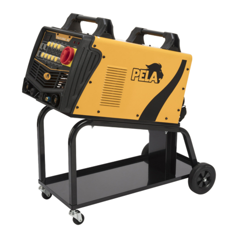
pela tools MIG 180 User manual

MIG 180
MIG 180
Item No:
513875

Kontaktinformation
Verktygsboden Erlux AB
Källbäcksrydsgatan 1
SE-507 42 Borås
Telefon: 033-202650
Mejl: [email protected]
Miljöskydd/Skrotning
Återvinn oönskat material, släng
det inte bland hushållssoporna. Alla
maskiner, tillbehör och förpackning-
ar skall sorteras och lämnas till en
återvinningscentral och där kasseras
på ett miljövänligt sätt.
Viktigt!
Läs noga igenom bruksanvisningen, säkerhetsin-
struktioner och monteringsanvisningar innan du
använder produkten. På så sätt får du ut mesta
möjliga och felaktig användning undviks. Spara
bruksanvisningen för framtida behov.
Allmänna säkerhetsföreskrifter
Vid arbete med maskiner bör följande punkter
alltid beaktas. Ta även hänsyn till arbetsplatsens
säkerhetsföreskrifter och respektera alla de lagar,
regler och förordningar som gäller där produkten
används.
-Städa ofta. Damm, avfall och bråte på en arbets-
plats ökar risken för olycka, brand och explosion.
-Arbeta inte i mörker eller dålig belysning.
-Förvara aldrig explosiva eller brandfarliga vätskor
och gaser inom arbetsområdet.
-Håll barn utanför arbetsområdet.
-Var särskilt uppmärksam på maskinens varnings-
symboler.
-Använd inte maskinen om du är trött eller påver-
kad av droger, alkohol eller medicin.
-Använd vid behov, skyddsutrustning såsom and-
ningsskydd, skyddshandskar, hörselskydd och
skyddsglasögon.
-Bär för ändamålet lämpliga arbetskläder och
halksäkra skor. Använd hårnät om du har långt hår,
bär inte smycken eller löst sittande kläder som kan
fastna.
-Låt aldrig din vana vid svetsen leda till oförsiktig-
het.
-Kontrollera att alla skydd sitter på plats och är i
god funktion. Kontrollera att alla delar är hela och
sitter korrekt monterade.
-Använd ej en defekt svets. Lämna in den till en
auktoriserad serviceverkstad för reparation.
-Använd endast rekommenderade tillbehör och
reservdelar. Eventuella reparationer och kabelbyte
ska utföras av behörig elekniker för att undvika
fara.
-Använd endast svetsen för avsett användningsom-
råde.
-Lämna aldrig svetsen obevakad när strömmen är
påslagen.
-Rengör svetsen efter användning och serva den re-
gelbundet. Förvara svetsen på en torr och skyddad
plats, oåtkomlig för barn.
-Utsätt inte svetsen för regn eller fukt.
-Behandla kablar varsamt och skydda dem från
värme, olja och vassa kanter. Förlängningskabel får
ej vara virad på en rulle, drag ut hela kabeln från
kabelvindan. Använd enbart korrekt dimensione-
rade förlängningskablar med tanke på längd och
kabelarea i förhållande till uttagen strömstyrka.
-Undvik kontakt med jordade ytor. Risken för elstöt
ökar när du är jordad.
Viktigt!
Svets och skärarbeten kan vara farliga för
operatören, medarbetare i omedelbar närhet och
för omgivningen om utrustningen inte hanteras på
rätt sätt.
Risk för ögonskada
Svetsbågen avger ultravioletta strålar, använd alltid
godkänd svetshjälm. Eventuell åskådare måste
också skydda sina ögon.
Risk för brännskada
Använd läderhandskar, kraghandskar när det
behövs och amsäker overall, knäpp ända upp i
halsen och vid handlederna så att eventuell svets-
loppa ej kan komma innanför kläderna.
Rör aldrig arbetsstycket, elektroden eller jordkläm-
man under eller precis efter arbetet. Risk för brand-
fara, svetsa aldrig i närheten av brännbart material.
Gnistor kan antända materialet lång tid efter det
att arbetet avslutats. Om brandfara föreligger skall
brandvakt vara utplacerad i minst en timma. Svetsa
inte bränsletankar, såvida du inte är en kvalifcerad
svetsare och har rengjort tanken ordentligt och
säkerställt att alla ångor är borta.
Risk för förgiftning
Det bildas giftig rök vid svetsning. Svetsa enbart i
välventilerad lokal. I mindre lokaler skall rökutsug
användas.
Säkerhetsanvisnigar
För att behålla prestanda för denna produkt under
en längre tid krävs regelbunden kontroll.
Var noga med att göra en regelbunden kontroll,
inklusive inspektion och rengöring av maskinen
inuti.
Den regelbundna kontrollen ska generellt utföras
en gång var sjätte månad. (Om det nns mycket n
smuts på svetsplatsen, eller om det nns mycket
oljig rök och rök där, bör regelbunden kontroll
utföras en gång var tredje månad).

Ta bort damm i maskinen - ta bort locket, ta bort
smuts eller ämnen som är svåra att blåsa bort.
Använd komprimerad luft utan vatten (torr luft) för
att blåsa upp det ackumulerade dammet inuti.
Rutinkontroll - ta bort locket och var uppmärksam
vid kontroll av följande delar och ickerutinmässiga
föremål. Kontrollera om det nns sällsynt lukt eller
överhettningsskador och om anslutningspunkterna
är lösa.
Kabelkontroll - se över alla kablar och säkerställ att
de är hela fungerar som de ska.
Om svetsen
Varning: se till att maskinens ström är av när du
sätter ihop svetsen.
Obs! Byt tillhörande förbrukningsvaror och kablar
när de är utslitna.
Det omgivande temperaturområdet vid arbete: -10
~ - +40
Svetsen ska användas i torr miljö.
Ljusindikator: Grön visar att svetsen är redo att
arbeta; gul betyder termiskt skydd och svetsen
måste kyls ned innan användning.
Eftergasfunktion: för att skydda eldsvetsning finns
det 3s eftergas vid slutet av svetsningen.
MMA Funktion: Val till detta läge görs på
frontpanelen.
Teknisk data
Spänning ………………………………...…… 230V
Frekvens …….....….........…................50 Hz
Nominell kapacitet …...…................7.4kVA
Ingen laddningsspänning .............65, 68, 70V
Svetsspänning ………………...............15.5-23V
Nominell arbetscykel …………….…… .20%
Svetsning Tråddiameter .............. .0,6-1,0 mm
Trådmatningshastighet ………………..2-10 m / min
Märksvetsström (MIG) ..................180A
Strömjustering (MIG) ……...............30-180A
Märksvetsström (stick) ................150A
Strömjustering (stick) ...….............30-150A
Vikt ……………………………………............11kg
Mått L * B * H ………………............... 44x19,5x28cm
Innan svetsning
-Anslut anslutningskablar och slangpaket.
Se till att strömmen är av när detta görs.
-Montera dit gasregulatorn.
-Skruva av mätarventilen (moturs), lossa trådhjulen,
tryck på strömbrytaren, justera gasödet till
processkraven och tryck sedan på matarvalsarna.
-Tryck in knappen på pistolen.
-Se till så att svetstråden matas fram.
Svetsning
Välj rätt svetsström beroende på materialtjocklek.
Val av svetsström görs med vredet på
frontpanelen.
MMA
Slå om omkopplaren från MIG till MMA och välj
sedan svetsström med vredet märkt MMA.
Underhåll
Korrekt användning och underhåll säkerställer god
svetsprestanda och svetsens långa livslängd. Un-
derhåll börs göra av experter. Försök hålla fackel-
kabeln rak när du svetsar. Frekvent rengöring inuti
munstycket ska göras. Använd svetstråd av god
kvalitet.
Installation
EXTREMIG 180 halvautomatisk gassvetsskydds-
klass IP21S.
Det måste vara väl jordat; jordkabeln får inte tas
bort innan svetsarbetet är slut. I annat fall kan
elektriska stötar uppstå, vilket kan leda till
personskada.

Svetsanslutningsdiagram
Anslut till ström
- Användaren måste ansluta den ström-kabeln på
baksidan av svetsmaskinen till eluttaget med
brytare.
- Användaren måste bekräfta att matningsspän-
ningen överensstämmer med spänningen i
typskylten på svetsmaskinen.
- Jordkabeln till eluttaget måste vara jordad.
Luftomkopplare A ≥ 40
Strömkabel mm2 ≥ 2,5
Anslut gassystemet
- Installera gasaskan och dra åt, se till att den inte
läcker.
- Kontrollera tryckmätaren på värmarens ödes-
regleringskontakt så att den sätts in i motsvarande
värmeutlopp.
- Den slumpmässiga annex luftröret, ena änden av
mätarens utloppsanslutning, den andra änden av
trådmataren är ansluten till inloppsrörsbeslagen,
dra åt med slangklämmor i varje ände.
Installera ledningssystemet i anslutningen
- När lämplig tråddiameter har valts enligt svets-
processens val, observera trådhjulens tråddiameter
och trådmatare. Kontrollera styrtrådsröret, slang-
trådsspetsens specikationer för att matcha.
- Skruva loss trådmataren, täckplåten för hylsax-
eln, plattans tråd i trådmatarens trådaxel. Obs!
Trådspolar ska gå nedåt mot trådmataren.
Skivtråden i hylsan är försedd med en dämpande
åtdragningsmekanism (skruva loss det sexkantiga
skruvaxelhöljet synligt) medan du drar tråden för
hand Grov skiva. Justera dämpningsbulten medurs
för att öka, minska och tvärtom. Vänligen slutför
justeringsaxelns lock.
Importera matningssvetsrör genom att trycka på
trådhjulet.
Anslutning av svetstrådsmatningssystemet
Anslut kabeln för att ansluta till den aktuella ut-
gångssvetsens frontpanel under ”+” -uttaget och
dra åt kontakten. I den andra änden av trådmata-
ren och den bakre änden av uttaget dras åt för att
säkra anslutningen.
Anslutningen till arbetsstycket
Motera jordkabeln i svetsen och sätt klämman i
materialet.
Obs! När svetsarbetet är slutfört eller om du
tillfälligt lämnar arbetsytan, bör svetsen också
stängas av på strömbrytaren och gasventilen.

Delar
1. Hållare
2. Gångjärn
3. Fall
4. Kontrollkort
5. EMC-kort (tillval)
6. Median septum
7. Frontplatta
8. Frontplatta
9. Svetsspänningspotentiometer ledningsnät
10. Lamphållare
11. Polaritetskabel
12. Potentiometer-ratt
13. Byt ledningsnät
14. Lager
15. Flänsplatta
16. Ledningsmatta med trådpotentiometer
17. Fackeluttag
18. Backboard
19. Trådmatare
20. Fläkt
21.1 Spolhållare
21.2 Justera muttern
21.3 Löshållare
21.4 Fjäder
21.5 Bult
22. Hållare, fast
23. Kabelhållare
24. Kraftledning
25. Magnetventil
26. Vippomkopplare
27. Dörrspärr

Felsökning
Huvudkretsschema


Contact
PELA Tools
Solängsvägen 13
SE-513 70 Borås
Phone: 033-202650
E-mail: [email protected]
Environmental protection/
Scrapping
Recycle any unwanted material,
do not throw it in the household
rubbish. All machines, accessories
and packaging must be sorted and
left at a recycling center and disposed
of in an environmentally friendly manner.
General safety instructions
-Clean often. Dust, waste and debris in a workplace
increase the risk of accident, re and explosion.
-Do not work in dark or poor lighting.
-Never store explosive or ammable liquids and
gases within the work area.
-Keep children out of the work area.
- Pay special attention to the machine’s warning
symbols.
-Do not use the machine if you are tired or under
the inuence of drugs, alcohol or medicine.
-Use if necessary, protective equipment such as
respiratory protection, protective gloves, hearing
protection and goggles.
-Wear suitable work clothes and non-slip shoes for
the purpose. Use hair nets if you have long hair, do
not wear jewelry or loose-tting clothing that can
get caught.
-Never allow your habit of the machine to lead to
carelessness.
-Check that all guards are in place and in good wor-
king order. Check that all machine parts are intact
and correctly mounted.
-Do not use a defective machine. Return it to an
authorized service workshop for repair.
-Use only recommended accessories and spare
parts. Any repairs and cable replacement must
be carried out by a qualied electrician to avoid
danger.
-Use only the machine for the intended use. The
work is always safer and faster if the machine is
used until it is designed for. Do not exceed applian-
ce capacity.
-Prevent unintentional start-up by disconnecting
power before servicing and repairing or when the
machine is not in use. Never leave a machine unat-
tended when the power is on.
-Clean the machine after use and service it regular-
ly. Store the machine in a dry and sheltered place,
out of the reach of children.
-Do not expose electrical machines to rain or
moisture if they are not approved for this. Outdoor
use only extension cables that are approved for
outdoor use.
- Treat cables carefully and protect them from heat,
oil and sharp edges. Extension cable must not be
wound on a reel, pull the entire cable out of the ca-
ble reel. Use only correctly dimensioned extension
cables in terms of length and cable area in relation
to the current drawn.
-Avoid contact with earthed surfaces. The risk of
electric shock increases when you are grounded.
Warning!
Welding and cutting work can be dangerous for the
operator, employees in the immediate vicinity and
for the environment if the equipment is not handled
correctly.
Risk of eye damage
The welding arc emits ultraviolet rays, always use
an approved welding helmet. Any spectator must
also protect their eyes.
Risk of burns
Wear leather gloves, collar gloves when needed
and tight-tting overalls, button all the way up to
the neck and at the wrists so that any welding ea
cannot get inside the clothes.
Never touch the workpiece, electrode or ground
clamp during or just after work. Risk of re, never
weld near combustible material. Sparks can ignite
the material long after the work is completed. If a
re hazard offers, the reghter must be deployed
for at least one hour. Do not weld fuel tanks, unless
you are a qualied
welder and have cleaned the tank thoroughly and
ensured that all vapors are gone.
Risk of poisoning
Toxic smoke is formed during welding. Weld only
in a well-ventilated room. In smaller rooms, smoke
extraction must be used.
Safety instructions
To maintain the performance of this product for a
long time, regular inspections are required.
Be sure to do a regular check, including inspection
and cleaning of the machine inside.
The regular check-up should generally be carried
out once every six months. (If there is very ne dirt
on the welding site, or if there is a lot of oily smoke
and smoke there, should be checked regularly and
once every three months).
Remove dust in the machine - remove the lid,
remove dirt or substances that are difcult to blow
off. Use compressed air without water (dry air) to
inate the accumulated dust inside.
Routine inspection - remove the cover and pay

attention when inspecting the following parts and
non-routine objects. Check for rare odors or over-
heating damage and loose connection points.
Cable check - review all cables and ensure that
they are intact working properly.
Power supply requirement
- Service voltage waveform should be actual sine
wave, frequency jitter is less than ±1% of rated
value.
- Fluctuation of service voltage is less than ±10% of
rated value.
- Unbalance rate of 1ph service voltage≤5%
About the welder
Caution: make sure the machine power is off when
assembling the torch
Note: Change the related consumables and cables
when they are worn out.
The surrounding temperature range when working:
-10~ - +40
Altitude less than 1000m
The welder should be used in a dry environment.
Light indicator: Green the welder ready to work;
yellow means thermal protection and need to wait
until it cooldown.
Low-speed-wire-feeding at the beginning of arc
striking, before the wire touch the work piece it is
set at a low speed.
After welding when trigger off the torch the wire
keeps feeding for a while. The function makes the
output Volt stay on for a short time to make sure
the wire fully burnt.
Under normal circumstances, the end of the wel-
ding wire ends often will be left a large droplet and
attached a layer of slag on its lower surface. It is
difcult to cause ignition of the arc again, for this
product has cut pellets circuit to automatically
when the end of the welding wire ends to remove
the droplet, thereby creating the conditions for the
next arc.
Post-gas function For protecting ery welding are
there is 3s post-gas at the end of welding.
Stick welding function Adjusting function switch to
stick welding on the front panel.
Technical Data
Voltage……………………………..….........…230V
Frequency………………………............….50 Hz
Max rated input current …..….........32 31 A
Rated capacity…………………..…........7.4kVA
No Loading Voltage………….......……65, 68, 70V
Welding voltage………………..…........15.5-23V
Rated duty cycle……………..……........20%
Welding Wire diameter ….…….......0.6-1.0 mm
Wire feed speed……………….….........2-10 m/min
Rated welding current(MIG)........180A
Current adjustment (MIG)…….......30-180A
Rated welding current (stick)…....150A
Current adjustment (stick)…….....30-150A
Weight………………………………….........11kg
Dimension L*W*H……………….......44x19.5x28cm
Before welding
-Connect various connection cables, torch, pipe,
installed wire, close the power switch and then the
machine fan rotation.
-Unscrew the carbon dioxide cylinder valve, pressu-
re indication on the gauge should be at this time.
-Unscrew the meter valve (counter-clockwise),
loosen wire wheels, press the torch switch, adjust
the gas ow to the process requirements, and then
pressing feed rolls.
-Press the torch switch wire to the torch end.
-When the torch cable wire straightening avoid
getting the wire blocked.
-When testing wire, to prevent the wire head wel-
ding head is blocked
-When the wire, please observe the wire is in the
groove feed rolls by, if outside the tank wire should
be adjusted to the trench (note wire and wire groo-
ve match).
Welding
Test welder observed voltage, current meter value
Meets Process Specication. Please adjust the
appropriate knob until it meets the parameters only
after welding.
Manual welding
The function switch on the front panel of the wel-
der from MIG to manual welding, connect the earth
clamp and welding clamp, welding current manual
knob to the need for welding current for welding.
Manual welding with a current preset function.
Care and Maintenance
Proper use and maintenance will ensure good
welding performance and long life of the welder.
Maintenance welder by professionals should be
made by professionals.
The welder should be stored in dry and ventilated
area, the temperature should be between -20 ~ +
55 °C and humidity less than 90%.

Keep the work area clean. Use compressed air to
remove dust hose (the dust is due to the accumula-
tion of friction welding hose), to ensure wire stabi-
lity.
When Welding, try to keep the torch cable straight.
Frequent cleaning inside the nozzle should be
done.
Use welding wire of good quality.
Installation
EXTREMIG 180 semi-automatic gas welding enclo-
sure protection class IP21S. When welding work
must not be less than 12.5mm diameter of a nger
or rod (especially metal rod) and is inserted into
the welder without pressure.
It must be well grounded; grounding wire must not
be removed before the end of the welding work
does not use welder. Otherwise, electric shock may
occur, resulting in personal injury. When the num-
ber of welding machines and other electrical equip-
ment or share a grounding device must be used in
parallel, prohibiting the use of a series.
Welding connection diagram
Connection to power
-The user must connect the 4-pin power cable in
the back of welding machine to the power outlet
with breaker.
-The user must conrm that the power supply
voltage is consistent with the voltage in the name-
plate on the welding machine.
-The earth cable of the power outlet must be groun-
ded.
-Power supply conguration of single welding
machine
Air switch A ≥ 40
Power cable mm2 ≥ 2.5
Connecting the gas system
- Install the gas cylinder and tighten, make sure it
does not leak.
- Check the pressure gauge on the heater ow
regulation plug wire so that it is inserted to the
corresponding heater outlet.
-The random annex trachea, one end of the meter
outlet connection, the other end of the wire feeder
is connected to the intake pipe ttings, tighten with
hose clamps on each end.
Install the wire system in the connection
- After suitable wire diameter is selected according
to the welding process selection, please note wire
wheels wire diameter and wire feeder. Check the
guide wire tube, hose wire torch tip specications
in order to match.
- Unscrew the wire feeder, sleeve shaft cover plate,
the plate wire into the wire feeder wire axis. Note:
Wire spools are supposed to go in a downward
direction against the wire feeder.
The disk wire within the sleeve is provided with
damping tightening mechanism (unscrew the
hexagonal screw shaft cover visible), while pulling
the wire by hand Coarse disc. Adjust damping bolt
clockwise to increase, decrease and vice versa.
Please complete the adjustment shaft cover tighte-
ned.
Import feed welding wire tube by pressing the wire
wheel.
Connecting the welding wire feed system
Connect the cable to plug into the current output
welder front panel below the ” +” socket and tigh-
ten the plug. In the other end of the wire feeder and
the rear end of the socket tighten to secure the
connection.
The 6 -core control cables were connected to both
ends of the plug at the bottom of the front panel
6-pin socket welding wire feeder and the rear end
of the 7 -pin socket and tighten.
Connection with the torch
The torch wire feeder connector into the front panel
of the interface gun and tighten.
The connection of the workpiece
The quick connector accessories supplied groun-
ding cable into the right side of the front panel with
the bottom welder ”-” the socket identity and clock-
wise to tighten, not loose, the other end clamped
workpiece.
Note: When the welding work is completed or you
temporarily leave the workspace, the welder should
be turned off on the power switch and gas valve
aswell.
welder should wear canvas overalls and welding
masks to prevent the arc light and heat.

Partlist
1. Holder
2. Hinge
3. Case
4. Control board
5. EMC board (option)
6. Median septum
7. Front plate
8. Front plate
9. Welding voltage potentiometer wire harness
10. Lamp holder
11. Polarity change cable
12. Potentiometer knob
13. Switch wire harness
14. Euro quick stocket
15. Flange plate
16. Wire potentiometer wire harness
17. Torch socket
18. Backboard
19. Wire feeder
20. Fan
21.1 Spool holder
21.2 Adjust nut
21.3 Holder end, Loose
21.4 Spring
21.5 Bolt
22. Holder end, Fixed
23. Cable holder
24. Power line
25. Solenoid valve
26. Rocker Switch
27. Door latch
Main Circuitchart

Troubleshooting
Common weld defects


Verktygsboden Erlux AB Källbäcksrydsgatan 1, SE-507 42 Borås
© Verktygsboden · Borås · Sweden · 0120504-03
This manual suits for next models
1
Table of contents
Languages:
Other pela tools Welding System manuals
Popular Welding System manuals by other brands

RPB
RPB Z3 instruction manual

Thermal Dynamics
Thermal Dynamics Pak Master 100XL operating manual

Miller Electric
Miller Electric Millermatic 140 Auto-Set owner's manual

Lincoln Electric
Lincoln Electric S350 CE Operator's manual

BossWeld
BossWeld X Series manual

Telwin
Telwin TIG AC/DC HF/LIFT MMA instruction manual

ESAB
ESAB Precision Plasmarc EPP-600 manual

Miller Electric
Miller Electric MS Weld Control owner's manual

Lincoln Electric
Lincoln Electric 180C Operator's manual

Lincoln Electric
Lincoln Electric InvertecV350-PIPE Operator's manual

Miller
Miller INVISION 350 MPa AUTO-LINE owner's manual

Spartus
Spartus ProCUT 85CNC user manual