manuals.online logo
Brands
  1. Home
  2. •
  3. Brands
  4. •
  5. Penn
  6. •
  7. Control Unit
  8. •
  9. Penn V246 Series User manual

Penn V246 Series User manual

V246 Series 2-Way Pressure-Actuated
Water-Regulating Valves for High-Pressure
Refrigerants Installation Guide
Applications
Important: The V246 Series 2-Way Pressure-
Actuated Water-Regulating Valves for High-Pressure
Refrigerants is intended to control coolant media
flow under normal operating conditions. Where
failure or malfunction of the V246 valve could
lead to personal injury or property damage to the
controlled equipment or other property, additional
precautions must be designed into the control
system. Incorporate and maintain other devices,
such as supervisory or alarm systems or safety or
limit controls, intended to warn of or protect against
failure or malfunction of the V246 valve.
Warning
Risk
This product is made of a copper alloy, which contains
lead. The product is therefore not to be used on drink-
ing water.
The V246 Series 2-Way Pressure-Actuated Water-
Regulating Valves for High-Pressure Refrigerants come
in two types of control action: direct acting and reverse
acting. V246 valves regulate water flow to control
refrigerant head pressure in systems with water-cooled
condensers.
The V246 Series Valves are available in 3/8 in. through 2
in. sizes and have a maximum allowable water pressure
of 150 psi (10.3 bar). Direct acting V246 valves have an
adjustable opening point in a refrigerant pressure range
of 200 to 400 psi (13.8 to 27.6 bar), and reverse acting
valves have a range of 135 to 300 psi (9.3 to 20.7 bar).
V246 valves may be used with standard non-corrosive
refrigerants.
Maritime models, which have nickel copper (Monel®)
internal parts, are available for applications where the
coolant may be corrosive to the internal parts.
Installation
CAUTION
Risk of Environmental Damage
Provide proper containment for any potential release
of refrigerant, solvent, or oil. Such hazardous materials
can be harmful to the environment if they are released.
Important:
• If the V246 valve is installed on equipment that
contains hazardous or regulated materials
such as certain refrigerants or lubricants, you
must comply with all standards and regulations
governing the containment and handling of those
materials.
• After installing the V246 valve, evacuate pressure
connection lines to remove air, moisture, and
other contaminants in a manner consistent
with applicable environmental regulations and
standards.
• Take care to prevent foreign materials such as
weld slag, thread burrs, metal chips, and scale
from entering the piping system. This debris can
damage or severely impede the operation of the
valve by embedding itself in the seats, scoring the
valve, and ultimately resulting in seat leakage.
If the debris becomes embedded in the seats,
subsequent flushing and filtering of the piping
system with the valve installed does not remedy
the problem.
Install the valve vertically with the range adjustment
screw on the top, and the sensing element and pressure
connection line on the bottom, to allow oil and refrigerant
to drain away from the valve sensing element.
Mount the valve so that the valve sensing element is
above the refrigerant tap point, if possible. If it is not
possible to mount the bellows of the valve above the tap
point, loop the capillary above the tap point and below
the bellows and then connect to the valve. Tap off of the
topside of the high side line. This minimizes the effect of
refrigerant oil in the capillary on valve reaction time.
Do not mount the valve in any position other than vertical
unless specified by the manufacturer of the equipment
on which the valve is installed. Follow the manufacturer's
installation instructions.
The direction of water flow is indicated by an arrow on the
valve body. See Figure 1.
Part No. 24-7664-2713 Rev. G
2019-06-20
V246
Setup and Adjustments
If the system is located in an area with high ambient
temperatures, refrigerant head pressures may remain
high enough during Off cycles to prevent the valve from
closing completely. In such instances, raise the opening
point pressure of the valve just enough to cause the valve
to stop flow to the condenser during compressor standby
periods.
Manually Flushing the Valve
Manually flush the fluid piping after installation to remove
filings, chips, or other foreign material. Manual flushing
does not affect valve adjustment.
To flush the valve, insert screwdrivers under both sides of
the valve spring guide and lift upwards. See Figure 1.
Figure 1: Manual Flushing
Pressure Connections
Warning
Risk of Personal Injury
Shut off the liquid supply and relieve pressure in the
line before servicing the valve. Contents of liquid lines
could be under pressure and the release of liquid un-
der pressure may cause severe personal injury.
Connect the refrigerant side of the valve to the high
pressure side of the system, preferably away from the
compressor as far as possible. Additional tubing may
be used to make the connection if needed. Use 1/4-inch
tradesize copper tubing.
Follow these guidelines when making pressure
connections:
• Purge all tubing and lines before making pressure
connections.
• Use pressure tap points located on the top side of
the refrigerant lines; these reduce the possibility of
oil, liquids, or sediment accumulating in the pressure
connection line or valve sensing element, which could
cause valve malfunction.
• Avoid sharp bends in the capillary tubes. Sharp bends
can weaken or kink capillary tubes, which may result in
refrigerant leaks or restrictions.
• Allow for slack in the capillary tubes to dampen
vibration. Mechanical vibration can weaken or damage
the capillary tubes.
• Avoid contact between the capillary tubing and sharp
or abrasive objects. Vibration or rubbing of sharp or
abrasive objects in contact with capillary tubes can
cause leaks.
• Coil and secure excess capillary tubing away from
contact with sharp or abrasive objects or surfaces.
Carefully loop any excess capillary tubing into smooth,
circular coils (minimum 2 in. [5 cm] diameter). Securely
fasten the coiled capillary tube.
• Do not overtighten flare nuts on pressure connection
line fittings. Overtightening flare connections may
damage the threads and result in refrigerant leaks. Do
not exceed 10 ft·lb (14 N·m) of torque when tightening
flare connections.
• Avoid severe pressure pulsation at pressure tap points.
Install pressure connection lines to pressure tap points
away from the compressor discharge to minimize
the effects of pressure pulsation from reciprocating
compressors.
Adjustments
The V246 valves are factory adjusted for the settings
shown in Table 1.
The opening point pressure (also called the crack-open
point) is the refrigerant pressure (at the valve’s sensing
element) necessary to just lift the valve disc off of the
valve seat and allow water to flow through the valve body.
Turning the range adjustment screw changes the opening
point pressure.
Use a standard service valve wrench or screwdriver to
adjust the opening point pressure.
• Turn the range adjustment screw counterclockwise to
raise the opening point pressure.
• Turn the range adjustment screw clockwise to lower the
opening point pressure.
Use a refrigerant pressure gauge to adjust the opening
point pressure. Operate the system at normal load
conditions and adjust the valve’s opening point to the
desired pressure. See Table 1 for refrigerant pressure
specifications.
Table 1: Specifications for V246 Series Valves for High-
Pressure Refrigerants
Valve Type Maximum
Refrigerant Pressure
at Sensing Element
Opening Point
Adjustment Range
Factory-Set Opening
Point
Direct
Acting
630 psi (43.4 bar) 200 to 400 psi (13.8 to
27.6 bar)
200 psi (13.8 bar)
Reverse
Acting
630 psi (43.4 bar) 135 to 300 psi (9.3 to
20.7 bar)
165 psi (11.4 bar)
Torque Specifications
To prevent water leakage, ensure that the spring housing
and sensing element screws are tightened to the torque
specification in Table 2. To prevent refrigerant leakage,
V246 Series 2-Way Pressure-Actuated Water-Regulating Valves for High-Pressure Refrigerants Installation Guide2
ensure that the 1/4 in. flare pressure connection is
tightened to 10 lb·ft (14 N·m).
Table 2: Maximum Torque Specifications, lb·in. (N·m)
Valve Size Spring Housing
Screws
Sensing
Element Screws
Flare Pressure Connection
3/8 in. 15 (1.7) 15 (1.7) 10 lb·ft (14 N·m)
1/2 in. 25 (2.8) 25 (2.8) 10 lb·ft (14 N·m)
3/4 in. 35 (4.0) 35 (4.0) 10 lb·ft (14 N·m)
1 in. 55 (6.2) 72 (8.1) 10 lb·ft (14 N·m)
1-1/4 in. 55 (6.2) 72 (8.1) 10 lb·ft (14 N·m)
1-1/2 in. 55 (6.2) 72 (8.1) 10 lb·ft (14 N·m)
2 in. 95 (10.7) 95 (10.7) 10 lb·ft (14 N·m)
Repair Information
Replacement of the sensing element, internal parts,
and the rubber diaphragm can be made. To obtain
replacement kit instructions and details:
• In North America, contact Johnson Controls® Product
Sales Operations Team at 1-800-275-5676.
• In Europe, contact your local sales office.
For North American replacement kit product code
numbers, see Table 3. For European replacement kit
product code numbers, see Table 4.
Table 3: North American Replacement Kits
Nominal
Valve
Size
Valve Type Seat Replacement
Kit Product Code
Number
Diaphragm
Replacement Kit
Product Code
Number
Sensing Element
Replacement Kit
Product Code
Number
Commercial STT14A-600R3/8 in.
Maritime/Navy STT14A-601R
DPM14A-600R SEP93A-600R
Commercial STT14A-603R3/8 in.
Low Flow Maritime/Navy Not Applicable
DPM14A-600R SEP93A-600R
Commercial STT15A-602R1/2 in.
Maritime/Navy STT15A-603R
DPM15A-602R SEP93A-601R
Commercial STT16A-601R3/4 in.
Maritime/Navy STT17A-613R
DPM16A-601R SEP93A-602R
Table 3: North American Replacement Kits
Nominal
Valve
Size
Valve Type Seat Replacement
Kit Product Code
Number
Diaphragm
Replacement Kit
Product Code
Number
Sensing Element
Replacement Kit
Product Code
Number
Commercial STT17A-609R1 in.
Maritime/Navy STT17A-611R
DPM17A-600R SEP93A-603R
Commercial STT17A-610R1-1/4 in.
Maritime/Navy STT17A-612R
DPM17A-600R SEP93A-603R
Commercial STT17A-610R1-1/2 in.
Maritime/Navy STT17A-612R
DPM17A-600R SEP93A-603R
Commercial STT18A-620R2 in.
Maritime/Navy STT18A-622R
DPM17A-601R SEP93A-604R
Table 4: European Replacement Kits
Nominal
Valve
Size
Valve Type Seat Replacement
Kit Product Code
Number
Diaphragm
Replacement Kit
Product Code
Number
Sensing Element
Replacement Kit
Product Code
Number
Commercial STT002N600R3/8 in.
Maritime/Navy STT14A-601R
DPM14A-600R SEP93A-600R
Commercial STT003N600R1/2 in.
Maritime/Navy STT15A-603R
DPM15A-602R SEP93A-601R
Commercial STT004N600R3/4 in.
Maritime/Navy STT17A-613R
DPM16A-601R SEP93A-602R
Commercial STT17A-609R1 in.
Maritime/Navy STT17A-611R
DPM17A-600R SEP93A-603R
Commercial STT17A-610R1-1/4 in.
Maritime/Navy STT17A-612R
DPM17A-600R SEP93A-603R
Commercial STT17A-610R1-1/2 in.
Maritime/Navy STT17A-612R
DPM17A-600R SEP93A-603R
Commercial STT18A-620R2 in.
Maritime/Navy STT18A-622R
DPM17A-601R SEP93A-604R
V246 Series 2-Way Pressure-Actuated Water-Regulating Valves for High-Pressure Refrigerants Installation Guide 3
Technical Specifications
Table 5: V246 Series 2-Way Pressure-Actuated Water-Regulating Valves for High-Pressure Refrigerants
Factory-Set Opening Point • Direct Acting 200 psi (13.8 bar)
• Reverse Acting 165 psi (11.4 bar)
Maximum Working Pressure 630 psi (43.4 bar)
Opening Point Adjustment
Range
• Direct Acting 200 to 400 psi (13.8 to 27.6 bar)
• Reverse Acting 135 to 300 psi (9.3 to 20.7 bar)
Media 150 psi (10.3 bar) Maximum,
-4°F to 170°F (-20°C to 77°C) glycol/water or liquids with low freezing points that are
compatible with valve materials
Compliance United States: cULus Listed; UL 207 File SFJQ.SA45221
Canada: cULus Listed; UL 207 File SFJQ7.SA45221
Applies to:
• V246GA1-001C
• V246GB1-001C
• V246HA1-001C
• V246HB1-001C
Note:
• The valve body and internal parts are not compatible with ammonia (R717).
• The design pressure marked on these components shall not be less than the
installed system working pressure or less than the values outlined in ASHRAE 15
for the charged refrigerant. After charging, mark the installed equipment with
the refrigerant type and oil used.
The performance specifications are nominal and conform to acceptable industry standards. For application at conditions
beyond these specifications, contact Johnson Controls/PENN Refrigeration Technical Support at 1-800-275-5676. Johnson
Controls shall not be liable for damages resulting from misapplication or misuse of its products.
Points of single contact
APAC Europe NA/SA
JOHNSON CONTROLS
C/O CONTROLS PRODUCT MANAGEMENT
NO. 32 CHANGJIJANG RD NEW DISTRICT
WUXI JIANGSU PROVINCE 214028
CHINA
JOHNSON CONTROLS
WESTENDHOF 3
45143 ESSEN
GERMANY
JOHNSON CONTROLS
507 E MICHIGAN ST
MILWAUKEE WI 53202
USA
© 2019 Johnson Controls. All rights reserved. All specifications and other information shown were current as of document revision and
are subject to change without notice.
www.penncontrols.com

This manual suits for next models

4

Other Penn Control Unit manuals

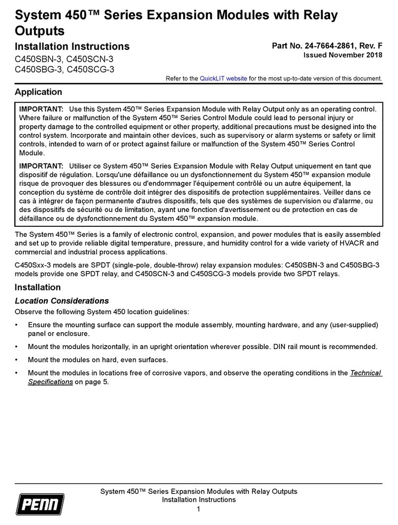
Penn System 450 Series User manual

Penn

Penn System 450 Series User manual

Penn V43 Series Manual

Penn

Penn V43 Series Manual

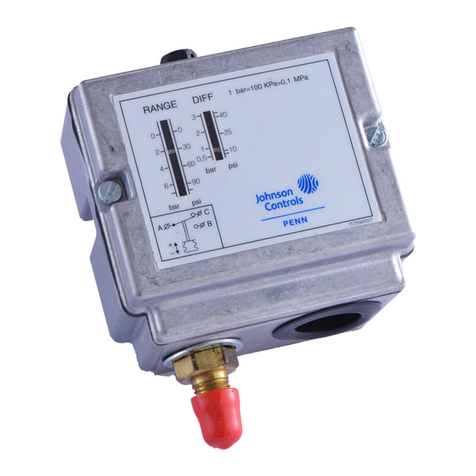
Penn P70 Series User manual

Penn

Penn P70 Series User manual

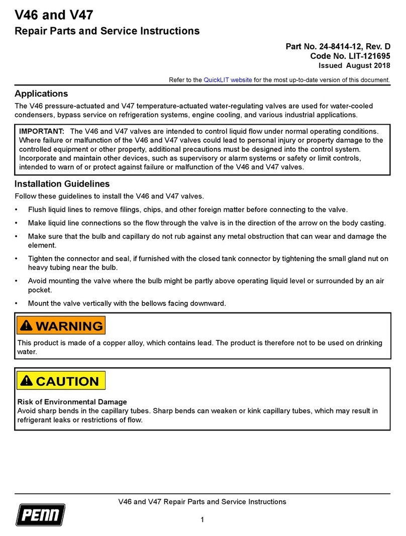
Penn V46 Series User manual

Penn

Penn V46 Series User manual

Penn System 450 Series User manual

Penn

Penn System 450 Series User manual

Penn System 450 C450RCN-1 User manual

Penn

Penn System 450 C450RCN-1 User manual

Penn P70C User manual

Penn

Penn P70C User manual

Penn QREV Series User manual

Penn

Penn QREV Series User manual

Penn A421 Series User manual

Penn

Penn A421 Series User manual

Penn P72 Series User manual

Penn

Penn P72 Series User manual

Penn P77 Series User manual

Penn

Penn P77 Series User manual

Penn V46 Series Use and care manual

Penn

Penn V46 Series Use and care manual

Penn System 450 Series User manual

Penn

Penn System 450 Series User manual

Popular Control Unit manuals by other brands

RAK RAK4600 quick start guide

RAK

RAK RAK4600 quick start guide

Hach IO9004 User instructions

Hach

Hach IO9004 User instructions

Pfeiffer Vacuum PM Z01 310 operating instructions

Pfeiffer Vacuum

Pfeiffer Vacuum PM Z01 310 operating instructions

resideo SmartValve SV9401 installation instructions

resideo

resideo SmartValve SV9401 installation instructions

AB Quality 1492-CM800-LD008 manual

AB Quality

AB Quality 1492-CM800-LD008 manual

National Instruments sbRIO-9651 Design guide

National Instruments

National Instruments sbRIO-9651 Design guide

Jetter JXM-IO-E32 user manual

Jetter

Jetter JXM-IO-E32 user manual

Siemens ST950 Installation Method Statement

Siemens

Siemens ST950 Installation Method Statement

DSE DSE8661 Operator's manual

DSE

DSE DSE8661 Operator's manual

ICP DAS USA tSH-735 quick start

ICP DAS USA

ICP DAS USA tSH-735 quick start

Eelectron DM03B01KNX quick start guide

Eelectron

Eelectron DM03B01KNX quick start guide

NPI PDES-01DM Operating instructions and system description

NPI

NPI PDES-01DM Operating instructions and system description

Nordson Liquidyn P-Jet CT operating manual

Nordson

Nordson Liquidyn P-Jet CT operating manual

Samson 3310/AT Mounting and operating instructions

Samson

Samson 3310/AT Mounting and operating instructions

comfortel HSE-S1501500EU instructions

comfortel

comfortel HSE-S1501500EU instructions

ADLINK Technology PXI-7931 user manual

ADLINK Technology

ADLINK Technology PXI-7931 user manual

TLV QUICK TRAP FS Series instruction manual

TLV

TLV QUICK TRAP FS Series instruction manual

elero VarioTec operating instructions

elero

elero VarioTec operating instructions

manuals.online logo
manuals.online logoBrands
  • About & Mission
  • Contact us
  • Privacy Policy
  • Terms and Conditions

Copyright 2025 Manuals.Online. All Rights Reserved.