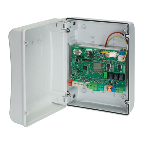
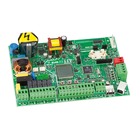
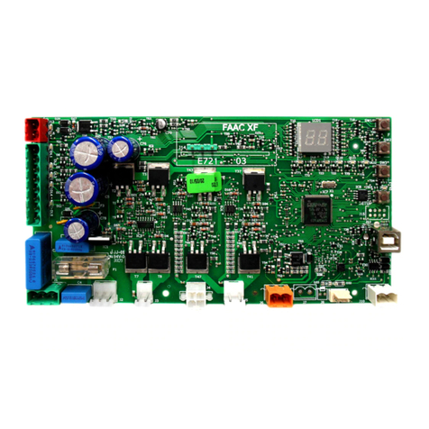
FAAC E124 Instruction Manual

1
ENGLISH
CE DECLARATION OF CONFORMITY
Manufacturer: FAAC S.p.A.
Address: Via Benini, 1 - 40069 Zola Predosa BOLOGNA - ITALY
Declares that: The E124 control unit
• ·conforms to the essential safety requirements of the following EEC directives
2006/95/EC Low Voltage Directive
2004/108/EC Electromagnetic Compatibility Directive
Additional note:
This product underwent tests in a typical uniform configuration
(all products manufactured by FAAC S.p.A.).
Bologna, 01 March 2008
The Managing Director
A.Marcellan
These instructions are to be considered
as a rapid guide for installation. The complete
instructions can be downloaded at the following
address: www.faacgroup.it
To access PROGRAMMING FROM PC, use the
X-COM module or connect the USB cable to the
dedicated connector and consult the dedicated
instructions.
E124 control unit – rapid guide
WARNINGS
• Important! For the safety of people, it is important that all the instructions be carefully observed.
• Incorrect installation or incorrect use of the product could cause serious harm to people.
• Carefully read the instructions before beginning to install the product and keep them for future reference.
•
The symbol indicates notes that are important for the safety of persons and for the good condition of the automated system.
• The symbol draws your attention to the notes on the characteristics and operation of the product.
Before attempting any work on the control unit (connections, maintenance), always turn off power.
Install, upstream of the system, a differential thermal breaker with adequate tripping threshold,
Connect the earth cable to the relevant terminal (see fig.5).
Always separate power cables from control and safety cables (push-button, receiver, photocells, etc.). To avoid any electrical disturbance, use separate
sheaths or a screened cable (with the screen earthed).
•
•
•
•
Primary power feed
from mains
with switching power feed
230/115 V~ - 50/60 Hz
Secondary power
feed
24 Vdc - 16 A max.
(min. 20 Vdc. - max. 28 Vdc.)
Power absorbed
from mains
stand-by = 4W
max. ~ 400 W
Max. load
for motor 7 A
Power feed
for accessories 24 Vdc
Accessories
max. current
24Vdc max. 500 mA
BUS-2EASY max. 500 mA
Battery charge
current 180 mA
Operating ambient
tempeature (-20 - +55) °C
Protective fuses All self resetting
Function logics Semiautomatic, Automatic,
“step-by-step” Semiautomatic, Automatic
with reverse during pause, Automatic
step-by-step, Safety devices automatic,
Safety devices step-by-step automatic,
“b” Semiautomatic, mixed logic “bC”,
Dead-man, Automatic with timer function
Work time Programmable (from 0 to 4 minutes)
Pause time Programmable (from 0 to 4 minutes)
Motor power Programmable on 50 levels
Motor speed Programmable on 10 levels
4 TECHNICAL SPECIFICATIONS
Connector inputs Switching feeder, Battery,
Decoder/Minidec/RP, X-COM, module
XF433/868, USB
Terminal board inputs BUS-2EASY, Inputs from IN1 to IN5 (see
par. 5), Travel limit device, Encoder.
Terminal board outputs
Flashing lamp, Motors, Electrical lock,
OUT1, OUT2 (programmable), power feed
to accessories
Programming
1st and 2° lev. with 3 keys (+, -, F) and LCD
display.
3rd lev. with P.C. connected via USB or with
X-COM module.

2
++
DL1
SW7
J4
J14
J13
J3
J5
J6 J7
J8 J9 J10
J2
J1
DL20
DL13
DL18
DL11
DL17
DL10
DL5
DL15
DL8
SW1
DL3 DL7DL6
SW3
DL16
DL12
DL19
DL9
SW2
DL2 DL4
ENGLISH
LAYOUT AND COMPONENTS OF E124
Terminal-board J4
IN1 OPEN A N.O. contact
IN2 OPEN B N.O. contact
IN3 STOP N.C. contact
IN4 FSW OP N.C. contact
IN5 FSW CL N.C. contact
INPUTS DEFAULT SETTING
POWER FEED
LED
Description
ON
(contact closed) OFF
(contact open)
DL1
IN1 -
OPEN A
Command enabled
Command disabled
DL2
IN2 -
OPEN B
Command enabled
Command disabled
DL3
IN3- STOP Command
disabled
Command enabled
DL4
IN4 - FSW
OP
Safety devices
disabled Safety devices tripped
DL5
IN5 - FSW
CL
Safety devices
disabled Safety devices tripped
DL6
FCA1
Opening travel-limit
devices free
Opening travel-limit
devices engaged
DL7
FCC1 Closing travel-limit
devices free
Closing travel-limit
devices engaged
DL8
FCA2
Opening travel-limit
devices free
Opening travel-limit
devices engaged
DL9
FCC2 Closing travel-limit
devices free
Closing travel-limit
devices engaged
DL10
ENC1 Flashing during operation
DL11
ENC2 Flashing during operation
DESCRIPTION OF COMPONENTS LED OPERATION
DL16
SIGNALLING LED FOR “SW1” PUSH-BUTTON (R1 PUSH-BUTTON)
DL17
SIGNALLING LED FOR “SW2” PUSH-BUTTON (R2 PUSH-BUTTON)
DL18
SIGNALLING LED FOR “SW3” PUSH-BUTTON (SETUP PUSH-BUTTON)
DL19 PRESSURE SIGNALLING LED “RESET SW” PUSH-BUTTON
DL20 ALARM SIGNALLING LED “ALARM”
J1
POWER FEEDER SWITCHING CONNECTOR (PRIMARY POWER)
J2 SECONDARY POWER SELECTOR
J3 CONNECTOR FOR CONNECTION TO BUS-2EASY DEVICES
J4
CONNECTOR FOR TERMINAL BOARD INPUTS (see chap.4.1)
J5 CONNECTOR FOR OUT2 OUTPUT (see 2nd level prog.)
J6 TRAVEL LIMIT INPUTS CONNECTOR
J7 CONNECTOR FOR LEAF 1 AND LEAF 2 ENCODER INPUTS
J8 CONNECTOR FOR OUT1 OUTPUT (see 2nd level prog.)
J9 FLASHING LAMP OUTPUT CONNECTOR
J10 CONNECTOR FOR ELECTRICAL LOCK OUTPUT
J13 CONNECTOR FOR RECEIVER MODULE XF433/XF868
J14 CONNECTOR: DECODER / MINIDEC / RP RECEIVER
115 Vac 230 Vac

3
**
*
TX CL
RX OP/CLTX OP/CL
+
+
+
+
J4
3
ON
1 2 3 4
BUSBUS
DL2
DL1
DS1 ON
1 2 3 4
BUSBUS
DL2
DS1
RX - TX
TX
ENGLISH
With the E124 control unit, you can use both
traditional photocells (N.C. contact with relay) and/or
photocells with BUS-2EASY (open collector contact).
ELECTRICAL CONNECTIONS
Connection of
traditional safety
devices and
photocells
Enable in
2nd level
programming
Use with motors
without a BUS-2EASY
encoder
Max load 24Vdc - 500mA
Connection of a pair of closing photocells and a pair of opening/
closing photocells with
disabled
FAIL-SAFE safety device and STOP
Connection of no safety device and STOP
CONNECTION OF TRADITIONAL SAFETY DEVICES
ADDRESSING THE BUS-2EASY PHOTOCELLS
Important: the same address must be given to
both transmitter and receiver. Make sure that
there are not two or more photocell pairs with
the same address. If you are not using any
BUS-2EASY accessory, leave free connector
BUS-2EASY
PHOTOCELLS BUS-2EASY
DL1 = Alignment
DL2 = BUS-2EASY/
power supply status
DS1 = Programming
dip-switches
Dip1 Dip2 Dip3 Dip4 Rif. Type
OFF OFF OFF OFF
B - C OPENING
OFF OFF OFF ON
OFF OFF ON OFF
OFF OFF ON ON
OFF ON ON OFF
OFF ON ON ON
ON OFF OFF OFF
D CLOSING
ON OFF OFF ON
ON OFF ON OFF
ON OFF ON ON
ON ON OFF OFF
ON ON OFF ON
ON ON ON OFF
OFF ON OFF OFF
AOPENING
and CLOSING
OFF ON OFF ON
ON ON ON ON / OPEN PULSE
The following table shows the programming operations of the
dip-switch inside the transmitter and the BUS 2-EASY photocells
receiver.

4
DL1
DL3
DL2
DL1
DL3
DL2
ENGLISH
6.2.2 MEMORY STORAGE OF BUS-2EASY ACCESSORIES
Cut power to the board.
Connect the two cables of the BUS-2EASY accessories to
the red terminal-board J3 (any polarity will do).
Power the board, taking care to first connect the plug
J1 of the main power supply (coming from the switching
feeder) and then, connector J2 of any batteries.
Quickly press once only the SETUP (SW3) push-button,
to execute learning. Check operation of the installed
BUS-2EASY devices.
1.
2.
3.
4. SAVING DS RADIO CONTROLS
On the DS radio control, select the required ON-OFF
combination for the 12 dip-switches.
Press push-button R1 (SW1) or R2 (SW2) to save respectively
total opening (OPEN A)or partial opening (OPEN B). The
relevant LED starts to flash slowly for 5 sec.
Release the push-button.
Within these 5 sec., press the appropriate push-button on
the radio control.
The relevant LED lights steadly for 1 second and
then goes OFF, indicating that storage was executed.
To add other different codes, repeat the procedure from
point 1.
To add radio controls with the same code, copy the same
ON-OFF combination on the other radio controls.
SAVING SLH RADIO CONTROLS
On the SLH radio control, simultaneously press and hold
down push-buttons P1 and P2.
The radio control LED begins to flash.
1.
2.
3.
4.
5.
6.
7.
1.
2.
6.2.3 ADDRESSING THE BUS-2EASY ENCODERS
Connection of the BUS-2EASY input in the control board is via
the bipolar cables which come out of the encoders.
Unlike the case of the photocell devices, the
polarity of the BUS-2EASY line connection
determines whether the encoder belongs to
one leaf rather than to the other.
Leaf 2
Leaf 1
Description of LED DL12 (RED)
ON Safety device engaged or pulse generator
active
OFF NO safety device engaged and NO pulse
generator active
Description of LED DL13 (GREEN)
Steady light Normal activity (LED Lighted even if no
photocells)
OFF Line BUS-2EASY short circuiting (flash every
2.5 sec.)
Fast flashing
Error detected in BUS-2EASY connection,
repeat the acquisition procedure. If the
error is repeated, make sure that there
is not more than one accessory with the
same address in the system (also see the
accessories instructions).
LED ON FLASHING OFF
DL 1
Power ON and
BUS -2EASY
communicating
with board
Power ON but
BUS-2EASY not
communicating
No power to or
communication
with BUS-2EASY
DL 2 Leaf 1 encoder / Leaf 2 encoder
DL 3
Leaf not moving Pulses read while
leaf moving
Leaf not moving
CONNECTOR J13 – XF MODULE RAPID CONNECTION
Release both push-buttons.
Press push-button R1 (SW1) or R2 (SW2) to save respectively
total opening (OPEN A) or partial opening (OPEN B). The
relevant LED starts to flash slowly for 5 sec.
Release the push-button.
Within these 5 sec., while the radio control LED is still flashing,
press and hold down the required push-button on the radio
control (the radio control LED lights steadly).
The LED on the board lights up on steady beam for 1
second and then goes OFF, indicating that storage was
executed.
Release the radio control push-button.
Quickly press twice the push-button of the saved radio
control.
3.
4.
5.
6.
7.
8.
9.
MEMORY STORAGE OF THE LC/RC RADIO CONTROLS (FOR
SOME MARKETS ONLY)
Use LC/RC remote controls only with a 433 MHz receiver
module.
Press push-button R1 (SW1) or R2 (SW2) to save respectively
total opening (OPEN A)or partial opening (OPEN B). The
relevant LED starts to flash slowly for 5 sec.
Release the push-button.
Within these 5 sec., press the appropriate push-button on
the LC/RC remote control.
The LED lights up on steady beam for 1 second, indicating
memory storage executed, and then resumes flashing for
another 5 sec., during which another radio control can be
memory stored.
When the 5 sec. have elapsed, the LED goes OFF indicating
the end of the procedure.
To add other radio controls, repeat the operation at point 1
1.
2.
3.
4.
5.
6.
7.
OFF

5
ENGLISH
1
ST
LEVEL PROGRAMMING press
Display Function Default
0
Default
1
Default
2
Default
3
dF
DEFAULT:
0Configures the parameters with DEFAULT values
corresponding to an installation with non-FAAC operators.
(see default column 0).
1Configures the parameters with DEFAULT values
corresponding to an installation with operators FAAC 412,
413/415, 770, 390 (see default column 1).
2Configures the parameters with DEFAULT values
corresponding to an installation with operators FAAC 391
(see default column 2).
3Configures the parameters with DEFAULT values
corresponding to an installation with operators FAAC S700H
(see default column 3.
CU If the CU value appears when you release the Fpush-button,
this means that a standard configuration modified by
push-buttons and display was selected. If you wish to
maintain this programming, press push-button Fagain.
PC If the PC value appears when you release the Fpush-button,
this means that programming from the PC was effected.
By pressing the +and -keys, you can load a default
configuration. If you wish to maintain programming from
the PC, press push-button Fagain.
0123
MO
TYPE OF MOTOR:
0non-FAAC operators.
1operators FAAC 412, 413/415, 770, 390.
2operators FAAC 391.
3operators FAAC S700H.
0123
LO
FUNCTION LOGICS:
ESemi-automatic.
AAutomatic.
EP Semi-automatic “Step by step”.
SA Automatic with in-pause reversing
AP Automatic “Step-by-step”.
S“Safety devices” automatic.
SP ”Step-by-step safety devices” automatic
bSemi-automatic “b”.
bC Mixed (OP at impulse/CL Dead-man)
CDead-man.
CU Custom.
At Automatic with timer function.
EEEE
PA
PAUSE TIME:
Can be adjusted from 0 to 59 sec. in one second steps. Next,
the viewing changes in minutes and ten secondsup to the
maximum value of 4.1 minutes.
20 20 20 20
F1
MOTOR 1 POWER:
01 = minimum power
50 = maximum power
25 25 25 25
F2
MOTOR 2 POWER:
01 = minimum power
50 = maximum power
25 25 25 25
SP
SPEED:
0 1 = minimum speed
1 0 = maximum speed
08 08 08 08

6
ENGLISH
Display Function Default
0
Default
1
Default
2
Default
3
rL
SLOW-DOWN:
00 = no slow-down
01 = minimum slow-down
99 = maximum slow-down
30 30 30 30
St
AUTOMATED SYSTEM STATUS:
00 = CLOSED
01 = OPEN
02 = Idle then “OPENS”
03 = Idle then “CLOSES”
04 = In “PAUSE”
05 = At opening stage
06 = At closing stage
07 = FAIL SAFE in progress
08 = verification of BUS-2EASY devices in progress
09 = Pre-flashing then “OPENS”
10 = Pre-flashing then “CLOSES”
11 = Opening in EMERGENCY status
12 = Closing in EMERGENCY status
2
nd
LEVEL PROGRAMMING
Display Function Default
0
Default
1
Default
2
Default
3
bo
MAXIMUM POWER AT THRUST:
The motors run at maximum power (ignoring the selected power
level F1 and F2), during motion thrust.
Y= active
no = excluded
no Y Y Y
EL
ELECTRIC LOCK AT CLOSING ON LEAF 2:
Y= electric lock at closing on leaf 2
no = electric lock at closing on leaf 1
no no no no
cd
LEAF DELAY AT CLOSING:
00 = no delay
01 = minimum delay in seconds
60 = maximum delay in seconds
20 20 20 20
od
LEAF DELAY AT OPENING:
Y = active
no = excluded
Y Y Y Y
t
WORK TIME (time-out):
Can be adjusted from 0 to 59 sec. in 1 second steps. Next, the
viewing changes in minutes and tenths of a second and time is
adjusted in 10 second steps, up to the maximum value of 4.1
minutes.
4.1 4.1 4.1 4.1
cS
FINAL CLOSING THRUST:
Y = active
no = excluded
no no no no
rS
REVERSING STROKE AT OPENING:
Y= active
no = excluded
no no no no
SF
SOFT TOUCH: (function active with FAAC operators only)
Y= active
no = excluded
no no no no
PF
PRE-FLASHING:
no = no pre-flashing.
OC = pre-flashing before every movement.
CL = pre-flashing before a closing motion.
OP = pre-flashing before an opening motion.
PA = pre-flashing at end of pause only
no no no no

7
ENGLISH
Display Function Default
0
Default
1
Default
2
Default
3
FA
TRAVEL-LIMIT STOP AT OPENING:
he use of travel limit stops at opening enables us to indicate the point
after which the equipment search for the mechanical stop point or to
immediately stop the automated system.
00 = no travel limit device at opening for both leaves
0 1 =
searches for stop point of leaf 1 and 2
04 =
stops movement of leaf 1 and 2
02 =
searches for stop point of leaf 1
0 5 = stops movement of leaf 1
03 =
searches for stop point of leaf 2
0 6 = stops movement of leaf 2
00 00 00 00
FC
TRAVEL-LIMIT STOP AT CLOSING:
The use of travel limit stops at closing enables us to indicate the point
after which the equipment search for the mechanical stop point or to
immediately stop the automated system.
00 = no travel limit device at closing for both leaves
0 1 =
searches for stop point of leaf 1 and 2
04 =
stops movement of leaf 1 and 2
02 =
searches for stop point of leaf 1
0 5 = stops movement of leaf 1
03 =
searches for stop point of leaf 2
0 6 = stops movement of leaf 2
00 00 00 00
An
ANTI WIND: (function only active with FAAC operators without
encoder)
00 = function disabled
2.0 = function active for maximum time
00 00 00 00
EC
ENCODER (for encoder connected both in J3-BUS-2EASY and in J7 )
1 = minimum sensitivity
10 = maximum sensitivity
07 07 07 07
Ph
CLOSING PHOTOCELLS:
Y = reversal at disengagement
n o = immediate reversal at opening
no no no no
Ad
ADMAP FUNCTION:
Y = active
n o = excluded
no no no no
o 1
OUT 1:
00 = FAIL-SAFE
02 = INDICATOR LIGHT (off when closed, lighted during opening
and open/pause, flashes during closing)
03 = COURTESY LIGHT (steady light for 90 sec.)
04 = ALARM on BATTERY operation
05 = gate OPEN or in PAUSE
06 = gate CLOSED
07 = gate MOVING
08 = gate in EMERGENCY status
09 = gate OPENING
1 0 = gate CLOSING
1 1 = ELECTRIC LOCK command before CLOSURE (you have to
interface with relay 24V – 100mA)
1 2 = safety device ACTIVE
1 3 =
‘TRAFFIC LIGHTS’ function (activates during OPENING and
when gate OPEN)
00 00 00 00
o2
OUT 2:
Used for setting output OUT2 (open collector N.O.).
See OUT1 settings.
02 02 02 02
X
RESET and X-COM RADIO MODULE ACQUISITION:
Y= X-COM module enabled to function.
no = no X-COM module fitted or configured.
no no no no

8
ENGLISH
ALARM AND ERROR SIGNALS
If alarms (conditions not prejudicing gate operation) or errors
(conditions preventing the gate from operating), the display
shows the number referring to the condition.
AS
ASSISTANCE REQUEST – CYCLES COUNTER (coupled to the next
two functions):
Y = When the number of cycles settable with the following nc
and nd functions is reached, this facility pre-flashes for 8
sec. (in addition to the pre-flashing already set with the PF
function) before every movement.
no = the following functions
nc and nd
indicate how many cycles
the system effected up to a maximum displayable amount
of 99.990.
no no no no
nc
CYCLE PROGRAMMING (THOUSANDS):
If AS = Y, the display indicates the number of the thousands of
cycles after which assistance is requested (settable from 0
to 99).
If AS = no, the display indicates the number of the thousands of
effected cycles. The displayed value updates itself as the
cycles follow, interacting with the nd values.
00 00 00 00
nd
CYCLE PROGRAMMING (TENS):
If AS = Y, the display indicates the number of tens of cycles after
which assistance is requested (settable from 0to 99).
If AS = no, the display indicates the number of the tens of
effected cycles. The displayed value updates itself as the
cycles follow, interacting with the nc values.
00 00 00 00
Display Function Default
0
Default
1
Default
2
Default
3
START-UP
TIME LEARNING - SETUP
By powering up the board if a SETUP was never
executed, or if the board requests it, the letters
S0 together with the SETUP (DL18) LED flash on
the display, to indicate that the SETUP must be
executed. Take the leaves to halfway their
travel (very important for a successful SETUP).
Hold down the SETUP (SW3) push-button, until the SETUP
(DL18) LED goes OFF and leaf 2 (if present) begins the
slowed down closing movement, stopping when it reaches
the mechanical stop point. At this stage, S1 flashes on the
display (setup: FIRST CLOSURE LEAF 2)
Leaf 1 starts the slowed down closing movement, stopping
when it reaches the closing mechanical stop. At this stage,
S2 flashes on the display (setup: FIRST CLOSURE LEAF 1)
Leaf 1 begins the slowed down opening movement,
followed by leaf 2 (if present) also slowed down. At this
stage, S4 flashes on the display (setup: OPEN)
When the opening mechanical stop point is reached, both
leaves stop and leaf 2 (if present) automatically restarts
to close at full speed, followed by leaf 1. At this stage, S5
flashes on the display (setup: FAST CLOSE).
When the closing mechanical stop point is reached, both
leaves stop and leaf 1 restarts to open automatically at
full speed followed by leaf 2 (if present). At this stage, S6
flashes on the display (setup: FAST OPEN).
If an automatic logic was selected, the board counts the
set pause and automatically closes the gate. Otherwise,
give an OPEN pulse to close the gate.
1.
2.
3.
4.
5.
6.
2 2 Limited current MOT1
2 3 Limited current MOT2
2 4 LAMP output short circuited
2 5 LOCK output short circuited
3 0 XF-module radio codes memory full
3 5 Timer function active
4 0 Cycles programmed at second programming level
(n C ) exhausted.
4 5 Battery operation
0 1 Board failure
0 2 Thermal protection active
0 3 Motor 1 faliure
0 4 Motor 2 faliure
0 5 Last movement performed
1 0 Both motor 1 travel limit devices engaged
1 1 Both motor 2 travel limit devices engaged
1 5 Time-out elapsed
1 7 Motor 1 encoder failure
1 8 Motor 2 encoder failure
These signals will disappear during the following
cycle only if the cause is removed.When an ALARM occurs,
LED DL20 starts to flash. When an ERROR occurs, LED DL20
goes ON at steady beam. If you simultaneously press keys
+ and – the display will show the number of the fault in
progress, as shown in the following table.
Other manuals for E124
5
Table of contents
Other FAAC Control Unit manuals