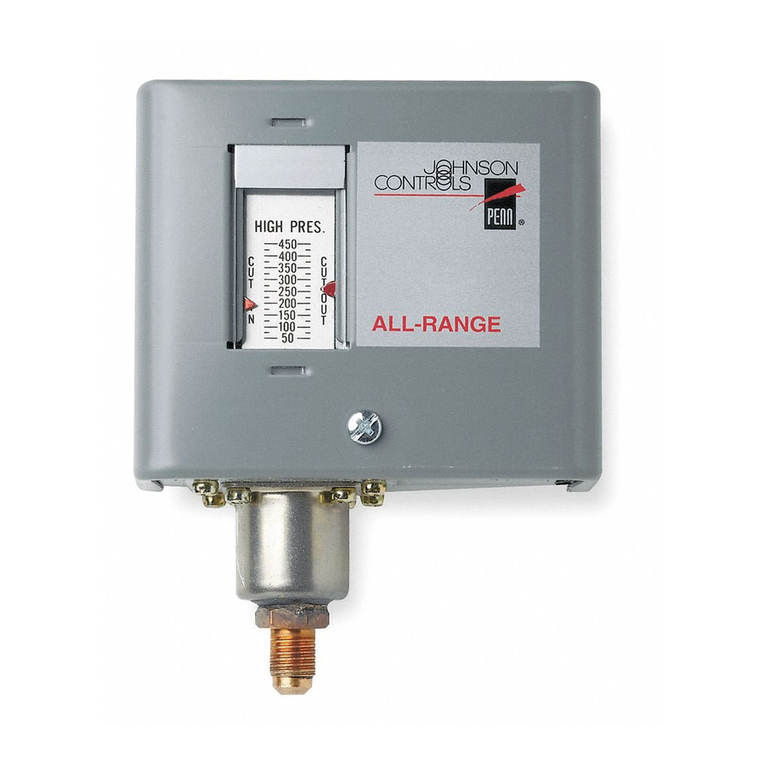
Penn P77 Series User manual

1
Refer to the QuickLIT website for the most up-to-date version of this document.
P77 Series Controls for High Pressure Applications Installation Instructions
Applications
P77 Series Controls for High Pressure Applications provide high pressure control of compressors on commercial
refrigeration and air-conditioning applications.
P77 control models with Single-Pole, Double-Throw (SPDT) switches allow users to install alarm devices or other
control circuits.
These controls are available in several pressure ranges and are compatible with most common refrigerants. They
may also be used on air, water, and other non-corrosive fluid applications.
High pressure P77BEA Type models with Manual Reset Lockout lock out when the Cut-out pressure is reached
and do not automatically reset after the control has cut out, providing shutdown capability for unmonitored
equipment. See Adjusting the P77 High Pressure Controls.
Type 1 enclosures are standard on most models.
IMPORTANT: Use this P77 Series Control only as an operating control. Where failure or malfunction of the control
could lead to personal injury or property damage to the controlled equipment or other property, additional precautions
must be designed into the control system. Incorporate and maintain other devices, such as supervisory or alarm
systems or safety or limit controls, intended to warn of or protect against failure or malfunction of the control.
IMPORTANT : Utiliser P77 Series Control uniquement en tant que dispositif de contrôle de fonctionnement.
Lorsqu'une défaillance ou un dysfonctionnement du contrôle risque de provoquer des blessures ou d'endommager
l'équipement contrôlé ou un autre équipement, la conception du système de contrôle doit intégrer des dispositifs de
protection supplémentaires. Veiller dans ce cas à intégrer de façon permanente d'autres dispositifs, tels que des
systèmes de supervision ou d'alarme, ou des dispositifs de sécurité ou de limitation, ayant une fonction
d'avertissement ou de protection en cas de défaillance ou de dysfonctionnement du contrôle.
P77 Series Controls for High Pressure Applications
Installation Instructions
P77AAA, P77BEA
Part No. 24-7664-3175, Rev. A
Issued September 2018

P77 Series Controls for High Pressure Applications Installation Instructions
2
Installation
Dimensions
See Figure 1 for control dimensions. These dimensions are nominal and subject to accepted manufacturing
tolerances and application variables.
Mounting
Guidelines: Observe the following guidelines to mount the P77 high pressure control:
• Mount the control in an accessible position, where the control and pressure-connection lines are not subject to
damage.
• Mount the pressure control upright and level.
• Position the pressure-connection lines to allow drainage away from the control bellows.
• Locate pressure-tap points on the topside of the refrigerant lines to reduce the possibility of oil, liquids, or
sediment accumulating in the bellows, which could cause control malfunction.
• Mount controls with Type 1 enclosures on horizontal or vertical flat surfaces.
Risk of Property Damage.
Mount the P77 Low Pressure Control according to the instructions and guidelines included with the control. These
instructions and guidelines are intended to reduce the risk of malfunction of the control and resulting property
damage. Failure to follow these instructions and guidelines could cause the control to malfunction, resulting in
property damage.
Risque de dégâts matériels.
Montez le contrôle P77 selon les instructions et directives fournies avec le contrôle. Ces instructions et directives
sont destinées à réduire les risques de mauvais fonctionnement du contrôle et de dégâts matériels. Le non-
respect de ces instructions et directives pourrait provoquer un dysfonctionnement du contrôle et causer des
dégâts matériels.
IMPORTANT: When mounting the control to a flat horizontal surface, use the screws provided and Universal
Mounting Bracket (sold separately) to avoid damaging internal components. Be careful not to distort or bend the
control case when mounting the control to an uneven surface. Using other screws or bending the control case
will void the warranty.
Figure 1: Dimensions of P77 High Pressure Control with Type 1 Enclosure, in. (mm)
Style 5 Connection Style 45 Connection

P77 Series Controls for High Pressure Applications Installation Instructions
3
Vertical Surface: Use four M4 x 6 mm + d screws (1) through the inner holes (2) on the back of the control case
when mounting directly to a flat vertical surface (3). The screws cannot be longer than 6 mm + d (where drefers to
thickness of mounting surface). (See Figure 2 and Table 1.)
Horizontal Surface: Use four M4 x 6 mm screws provided (4) and Universal Mounting Bracket (5) (sold
separately) when mounting to a flat horizontal surface (See Figure 2 and Table 1).
Table 1: Mounting the P77 High Pressure Control
Wiring
Callout Description
1 Mounting Screws for Vertical Surface (4), M4 x 6 mm + d (screws cannot be longer than 6 mm + d)
2 Inner Mounting Holes (4)
3 Flat Vertical Mounting Surface
4 Mounting Screws for Horizontal Surface (4), M4 x 6 mm (Provided)
5 Universal Mounting Bracket (Part Number 271-51, Sold Separately)
Risk of Electric Shock.
Disconnect or isolate all power supplies before making electrical connections. More than one disconnection or
isolation may be required to completely de-energize equipment. Contact with components carrying hazardous
voltage can cause electric shock and may result in severe personal injury or death.
Risque de décharge électrique.
Débrancher ou isoler toute alimentation avant de réaliser un branchement électrique. Plusieurs isolations et
débranchements sont peut-être nécessaires pour -couper entièrement l'alimentation de l'équipement. Tout contact
avec des composants conducteurs de tensions dangereuses risque d'entraîner une décharge électrique et de
provoquer des blessures graves, voire mortelles.
IMPORTANT: Use copper conductors only. Make all wiring connections in accordance with local, national, and
regional regulations. Do not exceed the control’s electrical ratings.
IMPORTANT: Use terminal screws furnished in the switch block. Using other terminal screws will void the
warranty and may damage the switch.
Horizontal Surface
Vertical Surface
Figure 2: Mounting the P77 High Pressure Control with Type 1 Enclosure

P77 Series Controls for High Pressure Applications Installation Instructions
4
P77 controls for high pressure applications are available with a Single-Pole, Double-Throw (SPDT) switch. Check
the label inside the control cover for the model number, switch action, and electrical rating. Check the wiring
terminal designations on the control switch block, and see the following wiring diagrams when wiring the control.
(See Figure 3 and Table 2.) Also see Technical Specifications.
Table 2: Single Pressure Control, Low Events, High Events, and Model Type
Refrigerant Connections
Switch and Action Low Event High Event Model Type
Single-Pole, Double-Throw (SPDT) A to B Closes on
Pressure Decrease
A to C Opens
Simultaneously
A to B Opens on
Pressure Increase
A to C Closes
Simultaneously
P77AAA
A to C Closes on
Pressure Decrease
A to B Opens
Simultaneously
A to B Closes on
Pressure Increase
A to C Opens
Simultaneously
P77BEA
Risk of Environmental and Property Damage.
Avoid sharp bends in the capillary tubes. Sharp bends can weaken or kink capillary tubes, which may result in
refrigerant leaks or restrictions of flow.
Risque de dommages environnementaux et dégâts matériels.
Éviter de former des coudes serrés avec les tubes capillaires. Les coudes serrés peuvent affaiblir les tubes
capillaires ou engendrer des pliures, ce qui risque de provoquer des fuites de réfrigérant ou d'en gêner
l'écoulement.
Figure 3: P77 Switch Wiring (SPDT)

P77 Series Controls for High Pressure Applications Installation Instructions
5
P77 high pressure controls with a Style 5 connection are connected to the controlled equipment by a capillary.
Capillaries are available from Johnson Controls, Inc. Refer to SEC99A, UltraCap Armored Capillary LIT-1900131
for more information.
Avoid severe pressure pulsation at high pressure connections. Install pressure connection to pressure-tap points
away from the compressor, to minimize the effects of pressure pulsation from reciprocating compressors.
Setup and Adjustments
Risk of Environmental and Property Damage.
Coil and secure excess capillary tubing away from contact with sharp or abrasive objects or surfaces. Vibration or
sharp or abrasive objects in contact with capillary tubes can cause damage that may result in refrigerant leaks,
which may result in damage to the environment or property.
Risque de dommages environnementaux et dégâts matériels.
Enrouler et fixer l'excédent de tubes capillaires de manière à éviter tout contact avec des objets coupants ou des
surfaces abrasives. Des vibrations ou des objets coupants ou abrasifs en contact avec les tubes capillaires risque
d'endommager ceux-ci et d'occasionner des fuites de réfrigérant, susceptibles de provoquer des dommages
environnementaux ou des dégâts matériels.
IMPORTANT: If the control is installed on equipment that contains hazardous or regulated materials such as
certain refrigerants or lubricants, you must comply with all standards and regulations governing the containment
and handling of those materials.
IMPORTANT: Do not apply more than 9 ft·lb (12 N·m) of torque to the flare nuts on pressure connection line
fittings. Over-tightening or applying more than 9 ft·lb (12 N·m) of torque may cause seal failure and will void the
warranty.
IMPORTANT: After installing the control, evacuate pneumatic and pressure connection lines to remove air,
moisture, and other contaminants in a manner consistent with applicable environmental regulations and
standards.
Risk of Property Damage.
Obtain and use the compressor manufacturer’s net oil bearing pressure specifications. If necessary, reset the
Cut-out pressure difference to the manufacturer’s specifications. Using improper pressure settings may damage
the control, compressor, or other controlled equipment.
Risque de dégâts matériels.
Consulter et utiliser les spécifications de pression nette de palier à huile fournies par le fabricant du compresseur.
Si nécessaire, réinitialiser la différence de pression d'ouverture sur les paramètres spécifiés par le fabricant.
L'utilisation de paramètres de pression inappropriés risque d'endommager le dispositif de contrôle, le
compresseur ou d'autres équipements contrôlés.
P77 Series Controls for High Pressure Applications Installation Instructions
6
Adjusting the P77 High Pressure Controls
Use the following procedures for adjusting these controls. Refer to the product label inside the control cover for
model number and switch action. See Table 2 for switch action, low event, high event, and model number.
High Pressure Cut-out - Automatic Reset: Models with Automatic Reset have a scaleplate that displays the
Cut-out and Differential setpoints (Item 1, Figure 4).
1. Set the Cut-in setpoint (High Event; A closes to C) by adjusting the range screw (2).
2. Turn the range screw clockwise to raise the Cut-in setpoint.
High Pressure Cut-out Controls: P77AAA
3. Set the Cut-out setpoint (Low Event; A opens to C) by adjusting the differential screw (3).
4. Turn the differential screw clockwise to increase the Cut-out setpoint.
High Pressure Cut-out Controls: P77AAA
Note: Cut-out is equal to Cut-in minus Differential
High Pressure Cut-out - Manual Reset Lockout: Models with the Manual Reset Lockout option have a
scaleplate that displays the Cut-out setpoint (Item 4, Figure 4). There is no scale for the Differential setpoint.
1. Set the High Event by adjusting the range screw (2).
2. Turn the range screw clockwise to raise the High Event.
High Pressure Cut-out Controls: P77BEA
Note: There is no Differential adjustment on Manual Reset Lockout models. The Differential pressure on P77 High
Pressure models is fixed at 44 psi (3 bar).
IMPORTANT: Use the pressure control settings recommended by the manufacturer of the controlled
equipment. Do not exceed the pressure ratings of the controlled equipment or any of its components when
checking pressure control operation or operating the controlled equipment.
IMPORTANT: After mounting, wiring, and evacuating the control, attach a reliable set of gauges to the
controlled equipment, and operate the equipment (at least) three cycles at the pressures necessary to verify
control setpoints and proper equipment operation.
IMPORTANT: Do not adjust pointers beyond the highest or lowest indicator marks on the control’s pressure
scale. Adjusting pointers beyond indicator marks may damage screw threads, may cause inaccurate control
operation, and will void the warranty.
Manual Reset Lockout
Automatic Reset
Figure 4: Adjusting P77 Controls for High Pressure Applications

P77 Series Controls for High Pressure Applications Installation Instructions
7
Table 3: Adjusting P77 High Pressure Controls
Checkout Procedure for P77 High Pressure Controls
Manual Reset Operation
Pressure controls with the Manual Reset option, lock out when they reach Cut-out pressure and must be manually
reset by the user to restart the controlled equipment. The manual reset mechanism is trip-free and cannot be
overridden by holding the Reset Button down.
When a control requires a manual reset, first determine what caused the control to cut out, and allow the sensed
pressure to fall at least 44 psi (3 bar) below the Cut-out pressure. Then press and release the Reset Button on the
front of the control to restore normal operation of the controlled equipment (see Item 5, Figure 4).
Technical Specifications
Callout Description
1 Range and Differential Scales
2 Range Screw
3 Differential Screw
4 Range Scale (only)
5 Reset Button
6 Pressure Connections
7 Adjustment Lock Plate (if applied)
IMPORTANT: Use the pressure control settings recommended by the manufacturer of the controlled
equipment. Do not exceed the pressure ratings of the controlled equipment or any of its components when
checking pressure control operation or operating the controlled equipment.
IMPORTANT: After installing the control, attach a reliable set of gauges to the controlled equipment, and
operate the equipment (at least) three cycles at the pressures necessary to verify control setpoints and proper
equipment operation.
Table 4: P77 Series Electrical Ratings
Volts AC 50/60 Hz
UL60730
24 120 208 240
–Primary
Contact
Secondary
Contact
Primary
Contact
Secondary
Contact
Primary
Contact
Secondary
Contact
Horsepower – 1 0.33 1 0.75 1 1
Full Load Amperes – 16 7.2 9.2 7.6 8 8
Locked Rotor Amperes – 96 43.2 55.2 45.6 48 48
Resistive Amperes 16 16 8 10 8 10 8
Pilot Duty VA 125 720 720 720 720 720 720
Note: When the Primary Contact is A–C, the Secondary Contact is A–B. When the Primary Contact is A–B, the Secondary
Contact is A–C.
Table 5: P77 Series Applications (Part 1 of 2)
Information Description
Product Switch Action Single-Pole, Double-Throw (SPDT)
Pressure Connection 7/16-20 UNF for 1/4 (6 mm) flare nut

P77 Series Controls for High Pressure Applications Installation Instructions
® Johnson Controls and PENN are registered trademarks of Johnson Controls in the
United States of America and/or other countries. All other trademarks used herein are the property
of their respective owners. © Copyright 2018 by Johnson Controls. All rights reserved.
www.penncontrols.com
European Single Point of Contact: NA/SA Single Point of Contact: APAC Single Point of Contact:
JOHNSON CONTROLS
WESTENDHOF 3
45143 ESSEN
GERMANY
JOHNSON CONTROLS
507 E MICHIGAN ST
MILWAUKEE WI 53202
USA
JOHNSON CONTROLS
C/O CONTROLS PRODUCT MANAGEMENT
NO. 22 BLOCK D NEW DISTRICT
WUXI JIANGSU PROVINCE 214142
CHINA
8
Ambient Storage
Conditions
Temperature: -40 to 140ºF (-40 to 60ºC)
Humidity: 0 to 95% R.H. Non-condensing
Enclosure Type 1: Cast Aluminum
Dimensions (H x W x D) Type 1 Enclosure: 4 x 3.5 x 2.5 in. (101 x 89 x 64 mm)
Approximate Shipping
Weight
Individual Pack: (Type 1 Enclosure): 1.1 lbs (0.5 kg)
Bulk Pack: (Type 1 Enclosure in multiples of 35 controls): 40 lbs (18.1 kg)
Compliance cULus Listed; UL 60730, File SA516
Table 6: UL Conformity Declaration Information
Information Description
Purpose of Control Pressure Operating Control: Automatic reset controls
Pressure Cut-out: Manual reset controls
Construction of Control Electromechanical
Number of Cycles Automatic: 30,000 Cycles
Manual Reset: 6,000 Cycles
Method of Mounting Control Independently-mounted control
Type 1 or Type 2 Action Automatic: Type 1; Type 1.C (Micro-Interruption)
Manual Reset: Type 2
Pollution Degree Category 3
Heat and Fire Resistance Category N/A
Rated Impulse Voltage 4,000 V
Ball Pressure Temperature N/A
Field Wiring Rating 194°F (90°C)
Maximum Working Pressure 479 psi (33 bar)
Cover Screw Torque Requirements
Instruction
Tighten Enclosure Screws to: 10 - 12 in·lb (1.1 - 1.4 N·m)
The performance specifications are nominal and conform to acceptable industry standards. For application at conditions beyond these
specifications Johnson Controls shall not be liable for damages resulting from misapplication or misuse of its products.
Table 5: P77 Series Applications (Part 2 of 2)
This manual suits for next models
2
Table of contents
Other Penn Control Unit manuals

Penn
Penn V43 Series Manual

Penn
Penn V246 Series User manual

Penn
Penn QREV Series User manual

Penn
Penn System 450 Series User manual

Penn
Penn A421 Series User manual

Penn
Penn System 450 C450RCN-1 User manual

Penn
Penn V46 Series Use and care manual

Penn
Penn V46 Series User manual

Penn
Penn P72 Series User manual

Penn
Penn P70 Series User manual