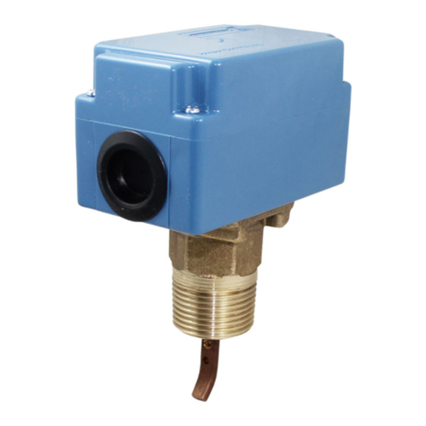
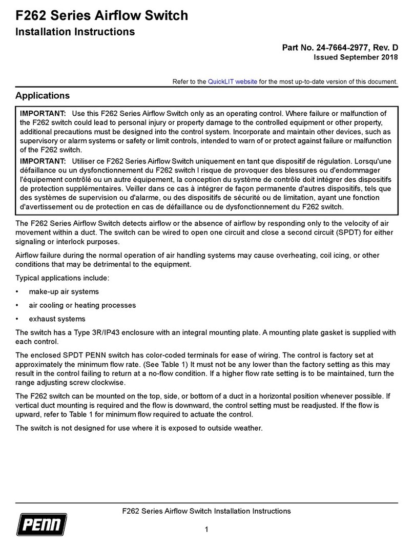
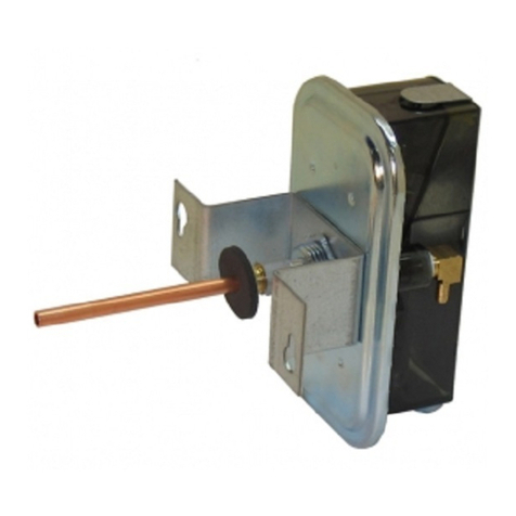
Penn F263 Series User manual

1
Refer to the QuickLIT website for the most up-to-date version of this document.
F263 Series Liquid Level Switches Installation Instructions
Applications
The F263 Series Liquid Level Switches are designed to maintain a liquid level in indoor or outdoor closed tanks
holding water or other non-corrosive liquids. When the liquid level in the tank rises above or falls below the required
level, the SPDT switch closes one circuit and opens a second circuit.
Use F263 Series Liquid Level Switches in closed tanks where a liquid level is to be maintained. A change in the
liquid level opens or closes an electrical circuit.
Use F263MAP switches on indoor or outdoor tanks that hold water or other nonhazardous liquids at temperatures
greater than the liquid's freezing point and between -20°F (-29°C) and 212°F (100°C). The maximum allowable
liquid pressure is 150 psig
(1035 kPa).
Use F263MAC switches on indoor or outdoor tanks that hold water or other nonhazardous liquids at temperatures
greater than the liquid's freezing point and between -20°F (-29°C) and 250°F (121°C). The maximum allowable
liquid pressure is 100 psig (690 kPa).
Note: Do not use these liquid level switches with liquids with a density less than the density of water.
IMPORTANT: Use this F263 Series Liquid Level Switch only as an operating control. Where failure or
malfunction of the liquid level switch could lead to personal injury or property damage to the controlled equipment
or other property, additional precautions must be designed into the control system. Incorporate and maintain other
devices, such as supervisory or alarm systems or safety or limit controls, intended to warn of or protect against
failure or malfunction of the liquid level switch.
IMPORTANT : Utiliser ce F263 Series Liquid Level Switch uniquement en tant que dispositif de régulation.
Lorsqu'une défaillance ou un dysfonctionnement du liquid level switch risque de provoquer des blessures ou
d'endommager l'équipement contrôlé ou un autre équipement, la conception du système de contrôle doit
intégrer des dispositifs de protection supplémentaires. Veiller dans ce cas à intégrer de façon permanente
d'autres dispositifs, tels que des systèmes de supervision ou d'alarme, ou des dispositifs de sécurité ou de
limitation, ayant une fonction d'avertissement ou de protection en cas de défaillance ou de dysfonctionnement
du liquid level switch.
IMPORTANT: Do not use F263MAC and F263MAP Liquid Level Switches where the fluid in the pipes drops
below the fluid’s freezing point, causing an internal freeze-up.
IMPORTANT: Do not use F263 Series Liquid Level Switches with hazardous fluids or in hazardous
atmospheres. Use in these conditions may cause malfunction or improper operation.
This product is made of a copper alloy, which contains lead. The product is therefore not to be used on drinking
water.
F263 Series Liquid Level Switches
Installation Instructions
Part No. 24-7664-2985, Rev. D
Issued August 2018

F263 Series Liquid Level Switches Installation Instructions
2
Installation
Dimensions
Installation Procedure
!
WARNING: Risk of Personal Injury.
Shut off the liquid supply and relieve pressure in the line before servicing the valve. Contents of liquid
lines could be under pressure and the release of liquid under pressure may cause severe personal
injury.
AVERTISSEMENT : Risque de blessure.
Couper l'arrivée de liquide et évacuer la pression présente dans la conduite avant toute intervention sur
la vanne. Les liquides à l'intérieur des conduites peuvent être sous pression et la libération soudaine de
liquide sous pression risque de provoquer des blessures graves.
IMPORTANT: Do not allow the float to touch the side of the tank or any other obstructions.
IMPORTANT: To avoid damaging the switch, do not tighten by grasping the switch enclosure. Use only the
wrench flats provided.
IMPORTANT: Do not remove the cover gasket or the wire grommet in the conduit opening. Removing these
items will allow moisture to enter and condensate to form inside a NEMA 3R enclosure.
Figure 1: F263 Float Switch with Type 4 (NEMA) Enclosure, Shown with Polycarbonate Float and
Copper Float Options Dimensions, in. [mm]
1/2
4
[102]
2
[51]
2-9/16
[65]
4-11/16
[119]
1/2 [13]
typical thread
engagement
1-11 1/2 NPT
(30 mm Hex)
2-3/4
[70]
1-3/8
[19]
1/2 in.
or PG-16
conduit
opening
13-3/16
[335] 12-7/16
[316]
5-3/16
[132] 4-7/16
[113]
1 [25]
diameter
1-1/16 [27]
diameter
3/4
[19]
FIG:F263_dmnsns
Copper Float
Polycarbonate Float

F263 Series Liquid Level Switches Installation Instructions
3
Install the F263 control into a properly threaded (and sealed) 1 in. diameter hole in the tank at the desired height for
the liquid level. Position the control with the arrow on the enclosure pointing upward. Ensure that the threads are
adequately sealed.
Wiring
Color-Coded Screw Terminals
IMPORTANT: To avoid damaging the float, ensure that the float is not subject to pressures exceeding these
limitations:
• 100 psig (690 kPa) for copper float
• 150 psig (1035 kPa) for polycarbonate float
!
WARNING: Risk of Electric Shock.
Disconnect the power supply before making electrical connections. The printed circuit
board and its components are at AC line voltage. Contact with components carrying
hazardous voltage can cause electric shock and may result in personal injury or death.
AVERTISSEMENT : Risque de décharge électrique.
Débrancher l'alimentation avant de réaliser tout raccordement électrique. Le circuit imprimé
et ses composants présentent une tension CA. Tout contact avec des composants porteurs
de tensions dangereuses risque d'entraîner une décharge électrique et de provoquer des
blessures graves, voire mortelles.
IMPORTANT: Use copper conductors only. Make all wiring connections in accordance with local, national, and
regional regulations. Do not exceed the flow switch’s electrical ratings.
IMPORTANT: Use the terminal screws provided
(8-32 x 1/4 in. binder head). Substitution of other screws voids the warranty and agency approvals.
Figure 2: Installing the Float Switch
240 mm
70 mm
FIG:F263_mnt

F263 Series Liquid Level Switches Installation Instructions
4
All F263 models have color-coded screw terminals.
• Red is common
• Red closes to Yellow on liquid level increase
• Red closes to Blue on liquid level decrease
The F263 switch has three color-coded terminals. Red is common. Remove the cover to make wiring connections.
See Figure 3 for terminal identification.
See Figure 4 and Figure 5 for suggested circuits for controlling liquid levels with several inches (or feet) between
minimum and maximum levels.
Table 1: F261 Control Switch Action
Flow Action Switch Closure
Increase Red to Yellow
Decrease Red to Blue
Figure 3: Terminal and Wiring Identification
Increase in Level
Above Setpoint Decrease in
Below Setpoint
Level
Red
Ye ll ow
Blue
FIG:F2 63_swtchactn
Figure 4: Circuit for Controlling Fill Levels
R
R
Y
Y
B
B
Pump In
R1
R2
Pump
R
High Level
F263 Switch
Low Level
F263 Switch
L
L
FIG:fill_lvl_cntr
l

F263 Series Liquid Level Switches Installation Instructions
5
Setup and Adjustments
Checkout Procedure
Before applying power, ensure that installation and wiring connections are made to job specifications.
After making all necessary adjustments and electrical connections, put the system into operation and observe at
least three complete operation cycles before leaving the installation site.
Operation
The F263 Float Switch controls water levels to within approximately 1/2 in. (13 mm).
When the liquid level falls approximately 1/2 in. (13mm) below the height at which the switch is installed, the switch
closes the red contact (common) to the blue contact. See Figure 6 and Figure 7.
!
CAUTION: Risk of Property Damage.
Do not set the switch lower than the factory setting. The switch is factory set at
approximately the minimum flow rate. A lower setting may result in the switch failing to
return to a no-flow position which may result in damage to the controlled equipment or other
property.
MISE EN GARDE : Risque de dégâts matériels.
Ne pas régler le commutateur sur une valeur inférieure au paramètre d'usine. Le
commutateur est réglé en usine sur une valeur correspondant environ au débit minimum.
Un réglage sur une valeur inférieure risque d'empêcher le commutateur de revenir sur une
position « aucun-débit », ce qui risque d'endommager l'équipement contrôlé ou de
provoquer d'autres dégâts matériels.
!
CAUTION: Risk of Property Damage.
Do not attempt to change sealed settings. Attempted adjustment may damage the control
or cause loss of calibration or other property damage.
MISE EN GARDE : Risque de dégâts matériels.
Ne pas essayer de modifier la position des éléments de réglage bloqués. Toute tentative de
réglage risque d'endommager le dispositif de contrôle ou de provoquer la perte des valeurs
d'étalonnage ou d'autres dégâts matériels.
IMPORTANT: All F263 switches are factory-set and factory-sealed. Do not attempt to change the factory
settings. Changing the factory settings voids the warranty.
Figure 5: Circuit for Controlling Dump Levels
R
R
Y
Y
B
B
Pump Out
R1
R2
Pump
R
High Level
F263 Switch
Low Level
F263 Switch
L
L
FIG:dmp_lvl_cn
trl

F263 Series Liquid Level Switches Installation Instructions
6
When the liquid level in the tank rises to the height at which the switch is installed, the switch closes the red contact
(common) to the yellow contact. See Figure 6 and Figure 7.
Repair Information
Do not make field repairs, except for replacement of the float. For a replacement control or float, contact the
nearest Johnson Controls/PENN distributor. For more information, contact Johnson Controls/PENN application
engineering at 1-800-275-5676.
Technical Specifications
Table 2: F263 Series Liquid Level Switch Electrical Ratings
Volts 50/60 Hz
UL60730/UL1059 EN60730
24 120 208 240 24 230
Horsepower –111––
Full Load Amperes –161010– 8
Locked Rotor Amperes –966060–48
Resistive Amperes 16 16 10 10 16 16
Pilot Duty VA 125 720 720 720 77 720
Table 3: UL Conformity Declaration Information (Part 1 of 2)
Information Description
Purpose of Control F263 Liquid Level Float Switch
Construction of Control Electronic independently mounted control
Number of Cycles 100,000 cycles
Figure 6: F263 Float Switch Setup
Dump
Fill
F
H
F
L
FIG:F263_flt_swtch_setup
Figure 7: Terminal and Wiring Identification
Increase in Level
Above Setpoint Decrease in
Below Setpoint
Level
Red
Ye ll ow
Blue
FIG:F2 63_swtchactn

F263 Series Liquid Level Switches Installation Instructions
7
Method of Mounting
Control
Mounting to sensed media vessel/orientation
Type 1 or Type 2 Action Type 1.C (Microinterruption)
External Pollution Situation Pollution degree 4
Internal Pollution Situation Pollution degree 2
Rated Impulse Voltage 4,000 VAC
Ball Pressure Temperature Enclosure: 266°F (130°C )
Switch Component: 252°F (122°C)
Control Adjustment
Instruction
-
Field Wiring Rating Wire/Cord Temperature Ratings:
• 140°F (60°C) only permitted when ambient air and media are less than 113°F (45°C)
• 167°F (75°C) only permitted when ambient air and media are less than 140°F (60°C)
• 194°F (90°C) only permitted when ambient air is less than 140°F (60°C) and media is
less than 167°F (75°C)
• 302°F (150°C) permitted when ambient air is less than 140°F (60°C) and media is less
than 249°F (121°C)
Vessel Pressure F263 Liquid Level Float Switch with Copper Float: 100 psi (690 kPa)
F263 Liquid Level Float Switch with Polycarbonate Float: 150 psi (1935 kPa)
F263 Series Liquid Level Float Switches
Switch SPDT
Enclosure UL: Type 4
CE: IP67
Wiring Connections Three color-coded screw terminals and one ground terminal
Conduit Connection One 7/8 in. (22 mm) hole for 1/2 in. trade size (or PG16) conduit
Pipe Connector 1 in. 11-1/2 NPT threads
Minimum Tank Diameter 9 in. (229 mm)
Maximum Liquid Pressure 100 psig (690 kPa) for copper float
150 psig (1,035 kPa) for polycarbonate float
Liquid Temperature Range Minimum: -40°F (-40°C) or liquid freezing point1
Maximum: 212°F (100°C) polycarbonate, 250°F (121°C) copper2
Ambient Conditions Minimum: -40°F (-40°C)1
Maximum: 140°F (60°C)2
Compliance North America: cULus Listed; UL 60730, File E6688;
FCC Compliant to CFR47, Part 15, Subpart B, Class B
Industry Canada (IC) Compliant to Canadian ICES-003, Class B limits
Europe: CE Mark – Johnson Controls declares that this product is in compliance with the
essential requirements and other relevant provisions of the EMC Directive and the Low
Voltage Directive.
Australia/New Zealand Mark: RCM Compliant
1. Ensure that the low liquid temperature combined with the low ambient temperature does not lead to the freezing the liquid
inside the body (or bellows, where appropriate). Please observe the liquid freezing point.
2. At higher temperatures, the maximum allowed liquid temperature becomes lower. The temperature inside of the electrical
switch should not exceed 158°F (70°C).
The performance specifications are nominal and conform to acceptable industry standards. For application at conditions beyond these
specifications, consult Johnson Controls/PENN Refrigeration Application Engineering at 1-800-275-5676. Johnson Controls shall not be liable
for damages resulting from misapplication or misuse of its products.
Table 3: UL Conformity Declaration Information (Part 2 of 2)

F263 Series Liquid Level Switches Installation Instructions
® Johnson Controls and PENN are registered trademarks of Johnson Controls in the
United States of America and/or other countries. All other trademarks used herein are the property
of their respective owners. © Copyright 2018 by Johnson Controls. All rights reserved.
www.penncontrols.com
European Single Point of Contact: NA/SA Single Point of Contact: APAC Single Point of Contact:
JOHNSON CONTROLS
WESTENDHOF 3
45143 ESSEN
GERMANY
JOHNSON CONTROLS
507 E MICHIGAN ST
MILWAUKEE WI 53202
USA
JOHNSON CONTROLS
C/O CONTROLS PRODUCT MANAGEMENT
NO. 22 BLOCK D NEW DISTRICT
WUXI JIANGSU PROVINCE 214142
CHINA
8
United States Emissions Compliance
This equipment has been tested and found to comply with the limits for a Class B digital device, pursuant to Part 15 of the FCC Rules. These
limits are designed to provide reasonable protection against harmful interference in a residential installation. This equipment generates, uses
and can radiate radio frequency energy and, if not installed and used in accordance with the instructions, may cause harmful interference to
radio communications. However, there is no guarantee that interference will not occur in a particular installation. If this equipment does cause
harmful interference to radio or television reception, which can be determined by turning the equipment off and on, the user is encouraged to try
to correct the interference by one or more of the following measures:
- Reorient or relocate the receiving antenna.
- Increase the separation between the equipment and receiver.
- Connect the equipment into an outlet on a circuit different from that to which the receiver is connected.
- Consult the dealer or an experienced radio/TV technician for help.
Canadian Emissions Compliance
This Class (B) digital apparatus meets all the requirements of the Canadian Interference-Causing Equipment Regulations.
Cet appareil numérique de la Classe (B) respecte toutes les exigences du Règlement sur le matériel brouilleur du Canada.
Table of contents
Other Penn Switch manuals
Popular Switch manuals by other brands

SMC Networks
SMC Networks GS5 FICHE Product overview

Pilz
Pilz PSEN ma1.4p-59 operating manual

Briggs & Stratton
Briggs & Stratton 71008 Installation and operator's manual

Siemens
Siemens SIRIUS 3SE51-QV.0 Series Original operating instructions

ATEN
ATEN CS-128A user manual

Gude
Gude Expert Power Control NET 24x manual