Pennsylvania Scale Company 7800 User manual

7800 Technical Manual
Page 2 of 102
For Tech Support Manuals and How to Videos go to pascale.com or email us at: techsuppo[email protected]
Table of Contents
Unpacking and Setup
3
Specifications
4
Connections
5
Updating The Firmware
6 – 8
Saving and Uploading Scale Parameters and Database to Micro SD Card
9 – 12
Operation Guide
Weighing, Counting, Check Weighing and Setpoint Relay Modes
13 – 17
Counting
18 – 21
Using the ID Database
22 – 28
Configuration and Calibration
Weighing Settings
29 – 33
Calibration
34 – 37
Counting Modes
38 – 40
ID Database
41 – 43
Communication Protocols (Ethernet IP)
44 – 56
Data Output
57 – 70
Time and Date
71 – 72
Options
73 – 76
User Settings
77 – 78
Set Points and Relays
79 – 83
Password
84 – 85
Scale External Commands
86 – 87
Wired Ethernet
88 – 91
WiFi
92 – 97
Parts List
98 - 102

7800 Technical Manual
Page 3 of 102
For Tech Support Manuals and How to Videos go to pascale.com or email us at: techsuppo[email protected]
Unpacking and Startup
Unpack the Scale
• DO NOT LIFT SCALE BY THE TOP
SPIDER OR SUB PLATFORM!
• Remove the molded foam top from
the carton. On 2 lb. and 5 lb. capacity
scales the platform is packaged on
top of this foam. Gently lift and
remove the stainless-steel platform
cover only.
• Remove any options which may be
packed with the scale.
• Carefully remove scale from the
packaging by grasping both sides of
the base.
Scale Setup
• Place the scale on a stable, level
surface for operation.
• Adjust the corner leveling feet until
the level bubble indicates the unit is
level.
• Firmly tighten hex jam nuts on the
leveling feet. (Any time the scale is
relocated, it should be leveled.)
• Remove the protective plastic wrap
from the platform and place the
platform on the spider.
•
Plug the scale into 110/120 VAC

7800 Technical Manual
Page 4 of 102
For Tech Support Manuals and How to Videos go to pascale.com or email us at: techsuppo[email protected]
SPECIFICATIONS
• Power AC line voltages 115/230 VAC, 50/60 Hz (Specify when ordering)
• Power Consumption 0.25A at 115 VAC, 0.13A at 230 VAC
• Circuit Protection RFI, EMI, ESD Protection ADC shielded
• Display: 800 X 320 dot resolution, and 4.6” full-color LCD display with resistive touch panel
• Indications for Gross, Net, Tare, Count, Piece Weight, % Accuracy, Check Weigh
Over/Under/Accept, Setpoint Status, Active ID and Base 2
• Operating Temperature 14℉to 104℉, -10℃to 40℃
• Internal Resolution 1/8,000,000
• Displayed Resolution. Standard 1/10,000. Up to 1/50,000
• 5 VDC excitation to power up to 12, 350 ohm load cells
• Dimensions 12” X 14” Platter Size 10 lbs. and above capacities, 8” X 8” 2 and 5 lbs. capacities.
• Four Year Limited Warranty
•OPTIONS:
oSecond base input
oBattery AC operation, built-in re-
chargeable system, 30+ hours of
operation
oPrinters for label, barcode label or receipt
printing
oBarcode Scanner
oUpgraded Internal Product DB,
o1500 and 3000 entries
o1 alarm buzzer mounted inside scale or
indicator
oBall-top transfer plate
oRoller conveyor
oSetpoint/relays DC or AC
oAlarm stack lights and buzzer
oCommunications:
• Wired Ethernet
• WiFi
• USB Virtual Com Port & HID/Keyboard
Emulation
• Bluetooth® Virtual Com Port &
HID/Keyboard Emulation
oAnalog output, 4-20ma or 0-10vdc
oCustom label design and setup
oCustom engineering for unique
applications

7800 Technical Manual
Page 5 of 102
For Tech Support Manuals and How to Videos go to pascale.com or email us at: techsuppo[email protected]
INTERNAL LOAD CELL AND REMOTE BASE CONNECTIONS
Connections:
RS‑232 PIN ASSIGNMENTS AND IMPLEMENTED FUNCTIONS
Connection to the Serial Port is made via a DB‑9 female connector found in the access area under
the scale. Internal Instrument connection is on the main Board, TB2 1 through 7
7800 Scale
7800 Indicator
Com 1
PIN#
Com 2
PIN#
Com 1
PIN#
Com 2
PIN#
TXD Transmit
2
TXD Transmit
2
Ground
1
Ground
1
RXD Receive
3
RXD Receive
3
TXD Transmit
2
TXD Transmit
4
Ground
5
Ground
5
RXD Receive
3
RXD Receive
5
+5VDC
6 & 8
+5VDC
6 & 8
+5VDC
7
+5VDC
7

7800 Technical Manual
Page 6 of 102
For Tech Support Manuals and How to Videos go to pascale.com or email us at: techsuppo[email protected]
Scale Firmware Update
The 7800 firmware may be updated in the field for firmware versions 1.20.00 and above. You can
determine the firmware version by pressing the MENU button from any operating mode, then INFO
which will display the screen below:
There are two sperate firmware files used by the system TST and HOST, circled in the above.
To update the firmware, save the EW-1000-TFT-TS - VX.XX.X.hex and HOSTXXXX.S19 (X=version number)
to a Micro SD Card.
7800 Scale:Unplug the scale from Power and underneath the display casting removing the 4 screens
that hold the mounting plate in place. Gently remove the cover plate to access the PC Board that is
mounted underneath. Insert the Micro into the port as shown below

7800 Technical Manual
Page 7 of 102
For Tech Support Manuals and How to Videos go to pascale.com or email us at: techsuppo[email protected]
7800 Indicator: Remove the Backplate and find the Micro SD Extention cable. Insert the SD Cable
withupdated firmware into the port.
Ensure the SD Card is inserted all the way and “clicks” into place
Press the MENU Button and then select USER and enable CHECK MEM CARD FoR FW as shown below
Press the MENU Button and then select and hold for 4 seconds the OPTIONS CONFIGURATION button to
acceess advanced options. Select MEM-CARD EXTENDER and enable as shown below

7800 Technical Manual
Page 8 of 102
For Tech Support Manuals and How to Videos go to pascale.com or email us at: techsuppo[email protected]
The 7800 will read the root folder files after
inserting the Micro SD card or powering the meter
with a Micro SD card already inserted. If the 7800
detects an LCD TFT upgrade, the user is queried
to upgrade the firmware. The user will not be
prompted again until a power cycle or the removal
and reinsertion of the Micro SD card.
Selecting YES will activate the firmware upgrade
process screen (see screen to the right). The LCD
TFT firmware host file is processed, and if the
firmware is different from the currently running
firmware (in the case of user selected file
selection), the firmware upgrade process is
permitted.
After the file has been processed, the LCD TFT flash memory is erased and this process takes less
than 20s. The bargraph will not show movement for this time. When the 7800 is writing the
firmware to the internal flash memory, the bargraph will show the progress.
When the LCD TFT firmware update has been completed, the 7800 will restart.
If the host firmware requires an update, the following screen will be shown.
If the above right screen is displayed, Select OK to access the host update screen, see immediate
right.
Select START to upgrade the host firmware.
After it completes, tap exit twice to return to the main screen.

7800 Technical Manual
Page 9 of 102
For Tech Support Manuals and How to Videos go to pascale.com or email us at: techsuppo[email protected]
Scale Settings; Saving to and Loading From the Micro SD Card
All settings can be saved to and loaded from a Micro SD card. This includes all settings but not the Mv/V
used for calibration
To Save Settings: Insert Micro SD Card and access the Display PC Board Assembly
Press and release the SW2 switch shown below:
The Scale Displays the Hardware Menu as shown below
Select CONFIG LOAD/SAVE

7800 Technical Manual
Page 10 of 102
For Tech Support Manuals and How to Videos go to pascale.com or email us at: techsuppo[email protected]
To Save Scale Parameters select SAVE PARM TO FILE
Save to File Menu appears. Select NEW FILE and enter a filename
Parameters are saved to the SD Card
To Load Scale Parameters Select READ PARM FROM FILE. In the OPEN FILE menu use the UP/DOWN
Keys to Highlight the file to load then select OPEN
Saved Parameters are loaded to the scale memory.

7800 Technical Manual
Page 11 of 102
For Tech Support Manuals and How to Videos go to pascale.com or email us at: techsuppo[email protected]
Database; Saving to and Loading From the Micro SD Card
The 7800 Database can be saved to or loaded from the Micro SD Card. To Access insert a micro SD card
then go to MENU and press and hold for 4 seconds the ID DATABASE button. This will open the
Database Management Menu Shown Below:
To Save Scale Parameters select SAVE DATABASE TO FILE
Save to File Menu appears. Select NEW FILE and enter a filename and ENTER
Database is now saved to the Micro SD Card.
To Load Database Select READ DATABASE FROM FILE. In the OPEN FILE menu use the UP/DOWN Keys to
Highlight the file to load then select OPEN

7800 Technical Manual
Page 12 of 102
For Tech Support Manuals and How to Videos go to pascale.com or email us at: techsuppo[email protected]
You many import 1 entry at time by using the OVERWRITE ONCE and SKIP or import all database entries
selecting OVERWRITE ALL. When complete press the EXIT button to return to the main menu.

7800 Technical Manual
Page 13 of 102
For Tech Support Manuals and How to Videos go to pascale.com or email us at: techsuppo[email protected]
Operation Guide
The 7800 Touchscreen count/weigh scale and indicator uses a windows type operating system allowing
the user to select the operational mode which only has the scale data and function buttons required for
that operation. Use from any of the main operating displays use the MODE button to cycle through the
available modes windows that are enabled. These include Weighing, Counting, Checkweighing and
Setpoint Relay mode windows.
WEIGHING MODE COUNTING MODE
CHECKWEIGHING MODE SETPOINT RELAY MODE
WEIGHING MODE, ID FUNCTION ENABLED WEIGHING MODE, ID FUNCTION DISABLED
WEIGHING MODE, CAPACITY DISPLAYED & ID FUNCTION ENABLED
ZOOM MODE OUT ZOOM MODE IN (TAP SCREEN TO ZOOM IN/OUT)

7800 Technical Manual
Page 14 of 102
For Tech Support Manuals and How to Videos go to pascale.com or email us at: techsuppo[email protected]
Scale Data Displayed
Function Buttons
Available
Operation Performed
Primary Display Field
GROSS WEIGHT Or
GROSS/NET
Configurable in Metrological Settings,
parameter 101 Main Weight Display
MENU Access calibration and
configuration menus
Second Display Field
NET WEIGHT
And
TARE WEIGHT
Configurable in Metrological Settings,
parameter 101 Main Weight Display
MODE
Cycles through
available operational
modes
Third Display Field
ACTIVE ID
Or Capacity
When ID, Description or Custom
Defined Data Fields are enabled in ID
Database Active ID is displayed and
Show Scale Capacity is Active
ID
When ID, Description or Custom
Defined Data Fields are enabled
in ID Database
Enter an ID number,
enter a new ID
number in database,
recall an ID number
from database.
DATA OUT
Sends formatted data
output string to one
or both comports
GROSS NET
Configurable in Metrological
Settings, parameter 101 Main
Weight Display
Cycles main display
field between Gross
and Net weight
TARE
Performs a platform
tare
KEYPAD TARE
Configurable in Metrological
Settings, parameter 100 Keypad
Tare Enable
Enter a known tare
value
ZERO
Zeros the scale
UNITS
Cycles through
primary and
secondary units

7800 Technical Manual
Page 15 of 102
For Tech Support Manuals and How to Videos go to pascale.com or email us at: techsuppo[email protected]
Counting Mode, ID Function Enabled Counting Mode, ID Function Disabled
Counting Mode, ID Function Enabled & Capacity Displayed
Scale Data Displayed
Function Buttons Available
Operation Performed
Primary Display Field
COUNT
MENU Access calibration and
configuration menus
APW (Average piece Weight)
ACCURACY/ERROR %
Configured in Counting Modes Menu
Parameter 56 Percent Mode and when ID
function enabled
MODE Cycles through available function
modes
Third Display Field
ACTIVE ID
When ID, Description or Custom Defined
Data Fields are enabled in ID Database
Active ID is displayed
OR
Percent ACCURACY/ERROR
Configured in Counting Modes Menu
Parameter 56 Percent Mode and when ID
function enabled
ID
When ID, Description or Custom Defined
Data Fields are enabled in ID Database
Enter an ID number, enter a new
ID number in database, recall an
ID number from database.
DATA OUT
Sends formatted data output
string to one or both comports
TARE
Performs a platform tare
KEYPAD TARE
Configurable in Metrological Settings,
parameter 100 Keypad Tare Enable
Enter a known tare value
ZERO
Zeros the scale
PIECE WEIGHT
Opens numeric keypad window
for entry of known piece weights
SAMPLE SET
Opens sample set window for
establishing a piece weight
through sampling process

7800 Technical Manual
Page 16 of 102
For Tech Support Manuals and How to Videos go to pascale.com or email us at: techsuppo[email protected]
Checkweigh Mode, ID Function Enabled Checkweigh Mode, ID Function Disabled
Checkweigh Mode, ID Function Enabled & Capacity Displayed
Scale Data Displayed
Function Buttons Available
Operation Performed
Primary Display Field
GROSS WEIGHT Or GROSS/NET
Configurable in Metrological Settings,
parameter 101 Main Weight Display
MENU Access calibration and
configuration menus
UNDER/ACCEPT/OVER
Checkweigh Bar graph
Checkweigh by weight or count
Configurable in Setpoint Configuration
Parameter 8 Set Point Enable
MODE Cycles through available function
modes
Third Display Field
ACTIVE ID
When ID, Description or Custom Defined
Data Fields are enabled in ID Database
Active ID is displayed
OR
TARGET WEIGHT/COUNT
Checkweigh by weight or count
Configurable in Setpoint Configuration
Parameter 8 Set Point Enable
ID
When ID, Description or Custom Defined
Data Fields are enabled in ID Database
Enter an ID number, enter a new
ID number in database, recall an
ID number from database.
DATA OUT
Sends formatted data output
string to one or both comports
TARE
Performs a platform tare
KEYPAD TARE
Configurable in Metrological Settings,
parameter 100 Keypad Tare Enable
Enter a known tare value
ZERO
Zeros the scale
UNITS
Change Unit of Measure
SETPOINT
Opens Setpoint Target entry
window for establishing a Target
and Tolerance Values

7800 Technical Manual
Page 17 of 102
For Tech Support Manuals and How to Videos go to pascale.com or email us at: techsuppo[email protected]
Set Point/Relay Mode, ID Function Enabled Set Point/Relay Mode, ID Function Disabled
Set Point/Relay Mode, ID Function Enabled & Capacity Displayed
Scale Data Displayed
Function Buttons Available
Operation Performed
Primary Display Field
GROSS WEIGHT Or GROSS/NET
Configurable in Metrological Settings,
parameter 101 Main Weight Display
MENU Access calibration and
configuration menus
______100%______
Setpoint/Relay Target Bar graph
Setpoint by weight or count
Configurable in Setpoint Configuration
Parameter 8 Set Point Enable
MODE Cycles through available function
modes
Third Display Field
ACTIVE ID
When ID, Description or Custom Defined
Data Fields are enabled in ID Database
Active ID is displayed
OR
TARGET WEIGHT/COUNT
Checkweigh by weight or count
Configurable in Setpoint Configuration
Parameter 8 Set Point Enable
ID
When ID, Description or Custom Defined
Data Fields are enabled in ID Database
Enter an ID number, enter a new
ID number in database, recall an
ID number from database.
DATA OUT
Sends formatted data output
string to one or both comports
TARE
Performs a platform tare
KEYPAD TARE
Configurable in Metrological Settings,
parameter 100 Keypad Tare Enable
Enter a known tare value
ZERO
Zeros the scale
UNITS
Change Unit of Measure
SETPOINT
Opens Setpoint Target entry
window for establishing a Target
and Tolerance Values

7800 Technical Manual
Page 18 of 102
For Tech Support Manuals and How to Videos go to pascale.com or email us at: techsuppo[email protected]
To Count an item using SAMPLE SET and ID DATABASE off
1 Step Counting In Counting Modes Set PARM 56 Two-SW APW SAMPLE To NO
If using a container to count parts into place this empty container on the scale
Use the MODE button to cycle through the counting mode window
Select the SAMPLE SET button to enter piece weight calculation Window.
Select from the 4 preset sample size buttons or PIECE SET. If PIECE Set is selected a sample quantity
window appears to enter a unique sample quantity.

7800 Technical Manual
Page 19 of 102
For Tech Support Manuals and How to Videos go to pascale.com or email us at: techsuppo[email protected]
Wait for the system to tare platform then prompt to add sample
Place the entire sample quantity ALL AT ONCE on the scale piece weight is calculated and Counting
Mode Window opens.
Place any additional items to be counted on the scale platform. Repeat the above steps for different
items to be counted.

7800 Technical Manual
Page 20 of 102
For Tech Support Manuals and How to Videos go to pascale.com or email us at: techsuppo[email protected]
2 Step Counting
2 Step Counting In Counting Modes Set PARM 56 Two-SW APW SAMPLE To YES
If using a container to count parts into place this empty container on the scale
Use the MODE button to cycle through the counting mode window
Select the SAMPLE SET button to enter the piece weight calculation Window.
Select from the 4 preset sample size buttons or PIECE SET. If PIECE Set is selected a sample quantity
window appears to enter a unique sample quantity.
Other manuals for 7800
1
Table of contents
Other Pennsylvania Scale Company Scale manuals
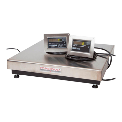
Pennsylvania Scale Company
Pennsylvania Scale Company 7800 User manual

Pennsylvania Scale Company
Pennsylvania Scale Company SS6600 MAX-LT User manual

Pennsylvania Scale Company
Pennsylvania Scale Company 7500 Series User manual

Pennsylvania Scale Company
Pennsylvania Scale Company 7600 User manual

Pennsylvania Scale Company
Pennsylvania Scale Company 7600 Manual

Pennsylvania Scale Company
Pennsylvania Scale Company MDL64 ABS User manual

Pennsylvania Scale Company
Pennsylvania Scale Company 7600 User manual

Pennsylvania Scale Company
Pennsylvania Scale Company 7700 Use and care manual

Pennsylvania Scale Company
Pennsylvania Scale Company 6500 Series User manual