Printed in U.S.A.
Page 19
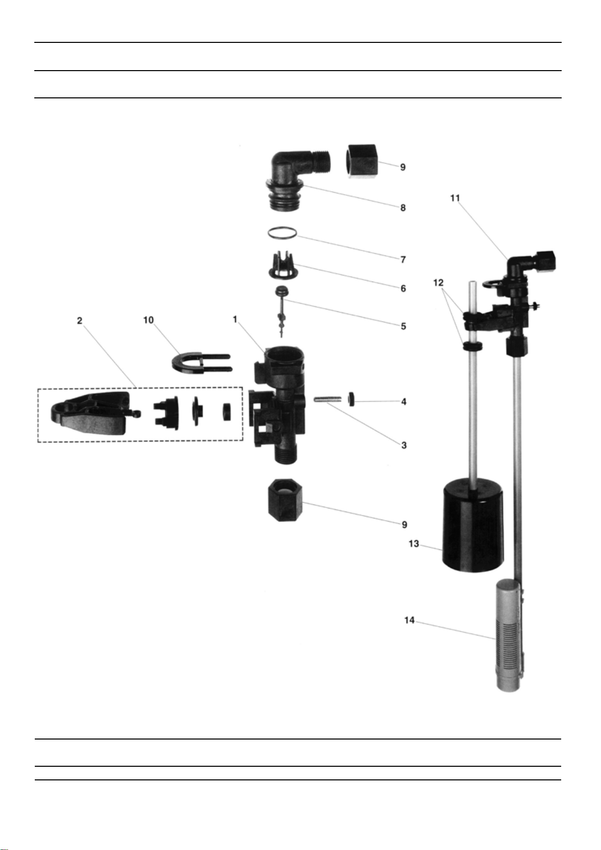
MODEL 5000SE Upflow
Control Valve Assembly
Parts List
Item No. Quantity Part No. Description
1. . . . . . . . . . . . 1 . . . . . . . . . . . . .18815. . . . . . . . . . . . . . . . . . Valve Body, 5000, 1″, Dist.
18815-20 . . . . . . . . . . . . . . . Valve Body, 5000, w/ mixing
2. . . . . . . . . . . . 1 . . . . . . . . . . . . .18264. . . . . . . . . . . . . . . . . . Spacer, End
3. . . . . . . . . . . . 4 . . . . . . . . . . . . .14241. . . . . . . . . . . . . . . . . . Spacer
4. . . . . . . . . . . . 5 . . . . . . . . . . . . .13242. . . . . . . . . . . . . . . . . . Seal
5. . . . . . . . . . . . 1 . . . . . . . . . . . . .18266. . . . . . . . . . . . . . . . . . Piston, Up-flow
6. . . . . . . . . . . . 1 . . . . . . . . . . . . .14309. . . . . . . . . . . . . . . . . . Retainer, Piston Rod
7. . . . . . . . . . . . 1 . . . . . . . . . . . . .18268. . . . . . . . . . . . . . . . . . End Plug Assembly
8. . . . . . . . . . . . 3 . . . . . . . . . . . . .18261. . . . . . . . . . . . . . . . . . Screw, Hex Washer Head, 10-24 x 13/16
9. . . . . . . . . . . . 1 . . . . . . . . . . . . .18267. . . . . . . . . . . . . . . . . . Piston Rod
10. . . . . . . . . . . . 1 . . . . . . . . . . . . .17978. . . . . . . . . . . . . . . . . . Brine Valve Stem
11. . . . . . . . . . . . 1 . . . . . . . . . . . . .18755. . . . . . . . . . . . . . . . . . O-Ring, -201
12. . . . . . . . . . . . 1 . . . . . . . . . . . . .13167. . . . . . . . . . . . . . . . . . Spacer, Brine Valve
13. . . . . . . . . . . . 1 . . . . . . . . . . . . .12550. . . . . . . . . . . . . . . . . . Quad Ring, -009
14. . . . . . . . . . . . 2 . . . . . . . . . . . . .13302. . . . . . . . . . . . . . . . . . O-Ring, -014
15. . . . . . . . . . . . 1 . . . . . . . . . . . . .13165. . . . . . . . . . . . . . . . . . Cap, Brine Valve
16. . . . . . . . . . . . 1 . . . . . . . . . . . . .11973. . . . . . . . . . . . . . . . . . Spring, Brine Valve
17. . . . . . . . . . . . 1 . . . . . . . . . . . . .16098. . . . . . . . . . . . . . . . . . Washer, Plain, Nylon
18. . . . . . . . . . . . 1 . . . . . . . . . . . . .11981-01 . . . . . . . . . . . . . . . Retaining Ring
19. . . . . . . . . . . . 1 . . . . . . . . . . . . .11183. . . . . . . . . . . . . . . . . . O-Ring, -017
20. . . . . . . . . . . . 1 . . . . . . . . . . . . . . . . . . . . . . . . . . . . . . . . . . . . Flow Washer (specify size)
21. . . . . . . . . . . . 1 . . . . . . . . . . . . .11385-01 . . . . . . . . . . . . . . . Flow Control Housing, Plastic
22. . . . . . . . . . . . 1 . . . . . . . . . . . . .18312. . . . . . . . . . . . . . . . . . Retainer, Drain
23. . . . . . . . . . . . 1 . . . . . . . . . . . . .13304. . . . . . . . . . . . . . . . . . O-Ring, -121
24. . . . . . . . . . . . 1 . . . . . . . . . . . . .18303. . . . . . . . . . . . . . . . . . O-Ring, -336
25. . . . . . . . . . . . 2 . . . . . . . . . . . . .10141. . . . . . . . . . . . . . . . . . O-Ring, -010
26. . . . . . . . . . . . 1 . . . . . . . . . . . . .18276. . . . . . . . . . . . . . . . . . Plug, Injector, Softener
27. . . . . . . . . . . . 2 . . . . . . . . . . . . .13771. . . . . . . . . . . . . . . . . . O-Ring, -012
28. . . . . . . . . . . . 1 . . . . . . . . . . . . .18275-X . . . . . . . . . . . . . . . . Injector Throat (specify size) 0000, 000, 00, 0, 1, 2
29. . . . . . . . . . . . 1 . . . . . . . . . . . . .18274-X . . . . . . . . . . . . . . . . Injector Nozzle (specify size) 0000, 000, 00, 0, 1, 2
30. . . . . . . . . . . . 1 . . . . . . . . . . . . .18273. . . . . . . . . . . . . . . . . . Vortex Generator
31. . . . . . . . . . . . 1 . . . . . . . . . . . . .18271. . . . . . . . . . . . . . . . . . Screen Injector
32. . . . . . . . . . . . 1 . . . . . . . . . . . . .18279. . . . . . . . . . . . . . . . . . Seal, Injector
33. . . . . . . . . . . . 1 . . . . . . . . . . . . .18278-20 . . . . . . . . . . . . . . . Cap, Regulated Injector, 20 PSI, Black
1 . . . . . . . . . . . . .18278-30 . . . . . . . . . . . . . . . Cap, Regulated Injector, 30 PSI, Gray
34. . . . . . . . . . . . 2 . . . . . . . . . . . . .18262. . . . . . . . . . . . . . . . . . Screw, Hex Washer Head, 10-24 x 1
35. . . . . . . . . . . . 1 . . . . . . . . . . . . .12977. . . . . . . . . . . . . . . . . . O-Ring, -015
36. . . . . . . . . . . . 1 . . . . . . . . . . . . .13245. . . . . . . . . . . . . . . . . . Retainer, BLFC Button
37. . . . . . . . . . . . 1 . . . . . . . . . . . . . . . . . . . . . . . . . . . . . . . . . . . . Flow Washer (specify size)
38. . . . . . . . . . . . 1 . . . . . . . . . . . . .13244. . . . . . . . . . . . . . . . . . Adapter, BLFC
39. . . . . . . . . . . . 1 . . . . . . . . . . . . .13308. . . . . . . . . . . . . . . . . . Hose Barb, Black, 1/2 x 1/2 Straight
1 . . . . . . . . . . . . .12338. . . . . . . . . . . . . . . . . . Hose Barb, Black, 1/2 x 1/2 90°Elbow
40. . . . . . . . . . . . 1 . . . . . . . . . . . . .18280. . . . . . . . . . . . . . . . . . Top Collector, 1″, X .011, Gray
1 . . . . . . . . . . . . .18280-01 . . . . . . . . . . . . . . . Top Collector, 1″, X .020 White, Wide Slot
1 . . . . . . . . . . . . .18280-02 . . . . . . . . . . . . . . . Top Collector, 1″, X .008 Red, Narrow Slot
41. . . . . . . . . . . . 1 . . . . . . . . . . . . .14613. . . . . . . . . . . . . . . . . . Flow Straightener
OPTION
Adapter Coupling Day Clock Only
45. . . . . . . . . . . . 2 . . . . . . . . . . . . .19228. . . . . . . . . . . . . . . . . . Adapter Coupling
46. . . . . . . . . . . . 4 . . . . . . . . . . . . .13305. . . . . . . . . . . . . . . . . . O-Ring, -119
47. . . . . . . . . . . . 2 . . . . . . . . . . . . .13255. . . . . . . . . . . . . . . . . . Clip, Mounting
48. . . . . . . . . . . . 2 . . . . . . . . . . . . .13314. . . . . . . . . . . . . . . . . . Screw, Hex Washer Head 8-18 x 5/8