manuals.online logo
Brands
  1. Home
  2. •
  3. Brands
  4. •
  5. Pentair
  6. •
  7. Control System
  8. •
  9. Pentair IntelliCenter 522039Z User manual

Pentair IntelliCenter 522039Z User manual

1
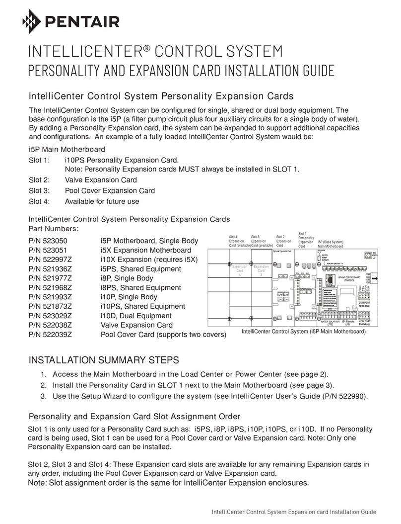
IntelliCenter Control System Expansion Card and Pool Cover Installation Guide IntelliCenter Control System Expansion Card and Pool Cover Installation Guide
INTELLICENTER™CONTROL SYSTEM
POOL COVER EXPANSION CARD AND POOL COVER INSTALLATION GUIDE
Slot 1 is only used for a Personality card such as: i5PS, i8P, i8PS, i10P, i10PS, or i10D. If no Personality
card is being used, Slot 1 can be used for a Pool Cover Expansion Card or Valve Expansion Card.
Note: Only one Personality Expansion Card can be installed in one enclosure. Note: For more information,
please refer to the IntelliCenter Control System Installation Guide (P/N 522989).
Slot 2, Slot 3 and Slot 4: These Expansion card slots are available for any remaining Expansion cards in
any order, including the Pool Cover Expansion card or Valve Expansion card. See figure 1.
Note: Slot assignment order is the same for IntelliCenter Expansion enclosures.
IntelliCenter Control System Pool Cover Expansion Card (P/N 522039Z)
The IntelliCenter Control System Pool Cover Expansion card can support two pool covers. Refer to
your pool cover manufacturer’s owner’s manual for wiring instructions. Note: For pool cover installation
instructions, see page 4.
INSTALLATION SUMMARY STEPS
1. Access the Main Motherboard in the Load Center or Power Center (see page 2).
2. Install the Pool Cover Expansion Card SLOT 1 (if available) next to the Main Motherboard or
in SLOT 2, SLOT 3, or SLOT 4 (see page 3).
3. Wiring the Pool Cover Expansion Card.
4. Use the Setup Wizard to configure the system (see IntelliCenter User’s Guide (P/N 522990)
i5P Main Motherboard
Slot 1: Personality Expansion Card.
Note: Personality Expansion cards MUST always be installed in SLOT 1.
Slot 2: Valve Expansion Card or Pool cover Expansion Card
Slot 3: Valve Expansion Card or Pool cover Expansion Card
Slot 4: Available for future use
Expansion Card Slot Assignment Order
(*) Slot 1:
Pool Cover
Expansion
Card
Slot 2:
Expansion
Card
Slot 3:
Expansion
Card (available)
Slot 4:
Expansion
Card (available) i5P (Base System)
Main Motherboard
Expansion
Card
3
Expansion
Card
4
Pool Cover Expansion Card
(P/N 522975)
1 2 3 4
ON C&K SDA 04
Pool Cover 2
Pool Cover 1
5V Power
Source
Figure 1: IntelliCenter Control System with Pool Cover Expansion Card Installed (i5P Main Motherboard)
Note: Use SLOT 1 for Pool Cover Expansion Card if no Personality Card is being used,
otherwise use SLOT 2, 3, or 4.
P/N 523457 Rev. C 8/2020
2
IntelliCenter Control System Expansion Card and Pool Cover Installation Guide IntelliCenter Control System Expansion Card and Pool Cover Installation Guide
Access the Outdoor Control Panel in the Load Center or Power Center
The IntelliCenter®Control System Main Motherboard Outdoor Control Panel is located in the top part of
the Load Center or Power Center enclosure. See Figure 2.
To access the Main Control Panel Motherboard:
1. Unlatch the front door spring latch and open the front door of the Load Center enclosure.
2. Loosen the two (2) retaining screws securing the high voltage cover-panel. Remove the HIGH
VOLTAGE COVER PANEL from the enclosure (as shown below).
BEFORE INSTALLING AN INTELLICENTER™ CONTROL SYSTEM EXPANSION OR
PERSONALITY CARD ALWAYS SWITCH OFF AC POWER TO THE LOAD AND/OR
POWER CENTER AT THE MAIN HOUSE CIRCUIT BREAKERS.
Figure 2: IntelliCenter Load Center Control System Load Center (front view)
(High Voltage Cover Panel removed)
High Voltage Cover Panel Tabs (3)
Remove two (2) retaining screws
securing High Voltage Cover Panel
Front door
High Voltage Cover Panel slots (3)
Flip down the Outdoor Control Panel to
access the Main Motherboard circuit board
Loosen Outdoor Control Panel
retaining screws
3. Install the Pool Cover Expansion Card onto the Main Motherboard (See Figure 3, page 3):
4. Carefully align the Pool Cover card edge connector (component side facing up) with the card edge
pins on the Main Motherboard (if using Slot 1) or other card. Slide the Pool Cover Expansion card
onto the card edge connector.
5. Secure the Pool Cover Expansion card in place with the two retaining screws (provided in kit).
3
IntelliCenter Control System Expansion Card and Pool Cover Installation Guide IntelliCenter Control System Expansion Card and Pool Cover Installation Guide
(*) Slot 1:
Pool Cover
Expansion
Card
Slot 2:
Expansion
Card
Slot 3:
Expansion
Card (available)
Slot 4:
Expansion
Card (available) i5P (Base System)
Main Motherboard
Expansion
Card
3
Expansion
Card
4
Pool Cover Expansion Card
(P/N 522975)
1 2 3 4
ON C&K SDA 04
Pool Cover 2
Pool Cover 1
5V Power
Source
Retaining
Screws
Figure 3. (*) Use SLOT 1 for Pool Cover Expansion Card if no Personality Card is
being used, otherwise use SLOT 2, 3, or 4.
7. When the wiring connections to the Pool Cover Expansion card are finished, close the hinged
control panel and secure it with the two retaining screws. Reinstall the High Voltage Panel and
insert the panel’s three tabs into the lower slots on the enclosure. Secure the panel with the two (2)
retaining screws. Close the front door and secure with the latch. See page 2 for illustration.
Access the Outdoor Control Panel in the Load Center or Power Center (Continued)
Wiring to the Pool Cover Expansion Card Digital Inputs
Pool Cover Expansion Card
(P/N 522975)
1 2 3 4
ON C&K SDA 04
DIGITAL INPUTS ANALOG INPUTS
Not Used
Pool Cover 2
Pool Cover 1
Not Used
Not Used
5VDC Power
Source
Figure 3. IntelliCenter™ Pool Cover Expansion Card Digital Inputs
6. For pool cover wiring instructions to the digital inputs, please refer to “Connecting the Rotary
Encoder to the IntelliCenter Control System Pool Cover Expansion Card” on the next page.
4
IntelliCenter Control System Expansion Card and Pool Cover Installation Guide IntelliCenter Control System Expansion Card and Pool Cover Installation Guide
Pool Cover Installation
The IntelliCenter Control System Pool Cover Expansion card can support two pool covers.
For more information, refer to your pool cover manufacturers owner’s manual for wiring instructions.
The pool cover controller provides the interface to the IntelliCenter Control System. The pool cover
controller is self powered and mounts to the non-motor end of an automatic safety cover mechanism.
Connecting the Rotary Encoder to the IntelliCenter Control System Pool Cover
Expansion Card
1. Connect the pool cover controller 2-wire (Black and White) to the Pool Cover 1, 2-pin digital input
screw terminals on the IntelliCenter Control System Pool Cover Expansion card.
See Figure 2.
2. Connect the black and white wires from the pool cover controller into one of the two Pool Cover
digital inputs. See Figure 1.
Pool Cover Expansion Card
(P/N 522975)
1 2 3 4
ON C&K SDA 04
DIGITAL INPUTS ANALOG INPUTS
Figure 1. Rotary Encoder 2-wire connector
Not Used
Figure 2. Pool Cover Expansion Card
Connect pool cover
controller Black and
White wires to
Pool Cover 1
(Digital Inputs)
Note: The following pool cover installation instructions described below may not be
the same for your pool cover equipment. Please refer to your pool cover
manufactures documentation for specific details.
Connecting the Pool Cover Controller to IntelliCenter™Control System
Expansion Card
Black
White
Pool Cover 1
5
IntelliCenter Control System Expansion Card and Pool Cover Installation Guide IntelliCenter Control System Expansion Card and Pool Cover Installation Guide
Pool Cover Installation (Continued)
Pool Cover Setup
Set Pool Cover Home Position
1. Operate the pool cover about 2 ft. (61 cm) from the fully open position. This will be the home
position for the pool controller. See Figure 3.
2. To zero the controller at the home position, press the button on top of the controller. The button
should blink three (3) times to verify it has been set. See Figure 4.
Figure 3. Pool Cover Home Position
Figure 4. Controller Button
Home Position
2 ft (61 cm)
6
IntelliCenter Control System Expansion Card and Pool Cover Installation Guide IntelliCenter Control System Expansion Card and Pool Cover Installation Guide
Pool Cover Installation (Continued)
Set Pool Cover Close Position
• After zeroing the controller, press the controller button to move the cover in the close direction,
approximately 10 ft. (305 cm). Then the pool controller will move the cover to the close position. The
controller now has a set home position and a close direction. See Figure 5.
10 ft (305 cm)
Figure 5. Pool Cover Set Position
7
IntelliCenter Control System Expansion Card and Pool Cover Installation Guide IntelliCenter Control System Expansion Card and Pool Cover Installation Guide
Pool Cover Installation (Continued)
Pool Cover Operating Positions
• The pool cover has two operating mode, OPEN and COVERED which are displayed on the
IntelliCenter Control System display. See Figure 6.
Figure 6. Pool Cover Before and After
Operating Modes
Home Position
Before Home Position
After Home Position
When the pool cover is located
at the “after” home position,
“open” is displayed on the
IntelliCenter Control System
display.
When the pool cover is located
at the “before” home position,
“covered” is displayed on the
IntelliCenter Control System
display.
Configuring IntelliCenter™ Control System for your pool cover
• For IntelliCenter pool cover operation and setup instructions please refer to page 8.
8
IntelliCenter Control System Expansion Card and Pool Cover Installation Guide IntelliCenter Control System Expansion Card and Pool Cover Installation Guide
Pool Cover Configuration from the IntelliCenter™ Control System Outdoor
Control Panel Display
From the IntelliCenter Control System Outdoor Control Panel Home screen
Pool Spa Features Lights
Air Temp 65° F
Schedule Usage Chemistry Status
3 3
10:10 am
6.50
0
4
84°
78°
1. From the Home screen, tap Settings >
Select Advanced System > Configurations >
Installation Setup > Pool/Spa Cover
2. Cover Enabled: Select Enable. Select either
Enabled or Disabled. Select Pool Cover 1.
3. Cover State Normally: Select either Closed
or Open for the state that the pool or spa
cover is usually in. Note: The pool cover
controller is set up as a normally open
configuration. Select Open.
4. Affected Circuits: Select Configure. Select
the features you want to turn off when the
pool cover is operating.
Select the circuits that you want to switch
OFF/ON when the pool or spa cover is closed
or open. Tap Check to save and return to the
Settings screen.
5. IntelliChlor Active (0-40): Select ON to switch
the IntelliChlor SCG circuit OFF when the
pool or spa cover is closed.
6. IntelliChlor Output: While the pool or spa
cover is closed, select the IntelliChlor SCG
chlorine output from 0 to 50 %.
7. Tap Return (multiple times) until you return to
the Home screen.
8. Tap Features.
Note: With the auto cover not in operation and
pool cover in the open position you have the
ability to turn on the features.
Note: When the auto cover is in operation or
the cover is closed the feature is no longer
available for selection.
The pool cover configuration is now complete
and ready for operation.
Note: For more information, please refer to
the IntelliCenter Control System User’s Guide
(P/N 522990)
Pool or Spa Cover Position: “OPEN” and “COVERED” is displayed on the Home screen to indicate the
current position of the cover.
Valve Type
Pool Cover 1 Sengs
Cover Enabled
20
IntelliChlor Output
Disabled
IntelliChlor Acve OFF
Configure...
Affected Circuits
Valve Type
Cover State Normally Open
Select Pool Cover
Cover 1
Cover 2
9
IntelliCenter Control System Expansion Card and Pool Cover Installation Guide IntelliCenter Control System Expansion Card and Pool Cover Installation Guide
NOTES
10
IntelliCenter Control System Expansion Card and Pool Cover Installation Guide IntelliCenter Control System Expansion Card and Pool Cover Installation Guide
NOTES
11
IntelliCenter Control System Expansion Card and Pool Cover Installation Guide IntelliCenter Control System Expansion Card and Pool Cover Installation Guide
NOTES
1620 HAWKINS AVE., SANFORD, NC 27330 • (919) 566-8000
10951 WEST LOS ANGELES AVE., MOORPARK, CA 93021 • (805) 553-5000
www.pentair.com
All indicated Pentair trademarks and logos are property of Pentair Inc. or its global affiliates in the U.S.A. and/or other countries. Third party
registered and unregistered trademarks and logos are the property of their respective owners
© 2020 Pentair. All rights reserved. This document is subject to change without notice.
P/N 523457 Rev. C 8/2020

Other Pentair Control System manuals

Pentair PENTEK DEFENDER CSC-LINK User manual

Pentair

Pentair PENTEK DEFENDER CSC-LINK User manual

Pentair ProValve User manual

Pentair

Pentair ProValve User manual

Pentair EasyTouch 8 User manual

Pentair

Pentair EasyTouch 8 User manual

Pentair EASYTOUCH PL4 User manual

Pentair

Pentair EASYTOUCH PL4 User manual

Pentair Hypro ProStop-E Quad 4216N-3404VPSQ User manual

Pentair

Pentair Hypro ProStop-E Quad 4216N-3404VPSQ User manual

Pentair INTELLICENTER User manual

Pentair

Pentair INTELLICENTER User manual

Pentair SunTouch User manual

Pentair

Pentair SunTouch User manual

Pentair SunTouch User manual

Pentair

Pentair SunTouch User manual

Pentair INTELLICENTER User manual

Pentair

Pentair INTELLICENTER User manual

Pentair AUTOTROL 460i User manual

Pentair

Pentair AUTOTROL 460i User manual

Pentair EasyTouch 8 and 4 User manual

Pentair

Pentair EasyTouch 8 and 4 User manual

Pentair EASYTOUCH PL4 User manual

Pentair

Pentair EASYTOUCH PL4 User manual

Pentair EasyTouch Installation and operation manual

Pentair

Pentair EasyTouch Installation and operation manual

Pentair EasyTouch Pool/Spa Control System LX-100EZ Installation instructions

Pentair

Pentair EasyTouch Pool/Spa Control System LX-100EZ Installation instructions

Pentair IntelliSync 523404 User manual

Pentair

Pentair IntelliSync 523404 User manual

Pentair INTELLICENTER User manual

Pentair

Pentair INTELLICENTER User manual

Pentair EASYTOUCH PL4 User manual

Pentair

Pentair EASYTOUCH PL4 User manual

Pentair IntelliSync 523404 User manual

Pentair

Pentair IntelliSync 523404 User manual

Pentair INTELLICONNECT User manual

Pentair

Pentair INTELLICONNECT User manual
Pentair Intellitouch ScreenLogic User manual

Pentair

Pentair Intellitouch ScreenLogic User manual

Pentair EasyTouch User manual

Pentair

Pentair EasyTouch User manual

Pentair Pool and Spa Control System SunTouch User manual
Pentair

Pentair Pool and Spa Control System SunTouch User manual

Pentair INTELLITOUCH User manual

Pentair

Pentair INTELLITOUCH User manual
Pentair SCREENLOGIC INTERFACE User manual
Pentair

Pentair SCREENLOGIC INTERFACE User manual

Popular Control System manuals by other brands

Kaba Saflok SYSTEM 6000 Reference manual

Kaba

Kaba Saflok SYSTEM 6000 Reference manual

Klimor EVO-T Operation and maintenance manual

Klimor

Klimor EVO-T Operation and maintenance manual

Siemens SIMATIC PCS 7 Getting started

Siemens

Siemens SIMATIC PCS 7 Getting started

Lutron Electronics Energi Savr Node QS DALI installation guide

Lutron Electronics

Lutron Electronics Energi Savr Node QS DALI installation guide

Crestron 4 Series product manual

Crestron

Crestron 4 Series product manual

Huawei IDS1000 user manual

Huawei

Huawei IDS1000 user manual

SIMDID DH728 Product instruction manual

SIMDID

SIMDID DH728 Product instruction manual

Kugelmann K-BASIC 2 Original operating instructions

Kugelmann

Kugelmann K-BASIC 2 Original operating instructions

JETI model duplex DC -24 II user manual

JETI model

JETI model duplex DC -24 II user manual

Belimo AFRB24-SR-S Technical data

Belimo

Belimo AFRB24-SR-S Technical data

Veeder-Root TLS-IB manual

Veeder-Root

Veeder-Root TLS-IB manual

BRAHMA EUROBOX Series manual

BRAHMA

BRAHMA EUROBOX Series manual

Rockwell Automation Allen-Bradley CENTERLINE 2100 installation instructions

Rockwell Automation

Rockwell Automation Allen-Bradley CENTERLINE 2100 installation instructions

Gamma Vacuum DIGITEL MPCe user manual

Gamma Vacuum

Gamma Vacuum DIGITEL MPCe user manual

iO HVAC Controls ZP3-HCMS Installation and operation instructions

iO HVAC Controls

iO HVAC Controls ZP3-HCMS Installation and operation instructions

Heras 411 Series installation manual

Heras

Heras 411 Series installation manual

Naish Fusion ATB Control System 2016 manual

Naish

Naish Fusion ATB Control System 2016 manual

RDM PR0029L-ACF user guide

RDM

RDM PR0029L-ACF user guide

manuals.online logo
manuals.online logoBrands
  • About & Mission
  • Contact us
  • Privacy Policy
  • Terms and Conditions

Copyright 2025 Manuals.Online. All Rights Reserved.