4
Ground motor before con-
necting to electrical power
supply.
Failure to ground motor
can cause severe or fatal
electrical shock hazard.
Do not ground to a gas
supply line.
To avoid dangerous or
fatal electrical shock, turn
OFF power to motor before
working on electrical connec-
tions.
Supply voltage must be
within ±10% of nameplate
voltage. Incorrect voltage can
cause fire or seriously damage
motor and voids warranty. If in
doubt consult a licensed electri-
cian.
Use wire size specified in
Wiring Chart (below). If
possible, connect pump to a separate branch circuit with no
other appliances on it.
Wire motor according to diagram on motor nameplate. If
nameplate diagram differs from diagrams below, follow
nameplate diagram.
WIRING
1. Install, ground, wire and maintain this pump in accordance
with your local electrical code and all other codes and ordi-
nances that apply. Consult your local building inspector for
local code information.
2. Ground the pump permanently using a wire of size and
type specified by local or National Electrical Code.
Do not ground to gas supply line.
3. Connect ground wire first. Connect to ground first, then to
green grounding terminal provided under motor canopy
(see Figure 3) identified as GRD. Make ground connection
to this terminal. Do not connect motor to electrical power
supply until unit is permanently grounded; otherwise seri-
ous or fatal electrical shock hazard may be caused.
4. For best ground connection, connect to a grounded lead in
the service panel or to a metal underground water pipe or
well casing at least 10 ft. long. If plastic pipe or insulated
fittings are used, run ground wire directly to the metal well
casing or use ground electrode furnished by the power
company.
WARNING
Hazardous voltage.
Can shock, burn, or
cause death.
Ground pump before
connecting to power
supply.
TABLE II - RECOMMENDED FUSING AND WIRING DATA - 60 CYCLE MOTORS
DIAMETER IN FEET FROM MOTOR TO METER
BRANCH 0’ 51’ 101’ 201’ 301’ 401’
MOTOR MAX. LOAD FUSE* TO TO TO TO TO TO
HP AMPERES RATING 50’ 100’ 200’ 300’ 400’ 500’
AMPS WIRE SIZE
SINGLE PHASE - 115 VOLT
1/3 9.4 15 14 14 12 10 8 8
1/2 9.4 15 14 14 12 10 8 8
3/4 12.2 20 12 12 10 8 6 4
1 14.8 20 12 12 8 6 6 4
1-1/2 19.2 30 10 10 8 6 4 2
SINGLE PHASE - 230 VOLT
1/3 4.7 15 14 14 14 14 14 12
1/2 4.7 15 14 14 14 14 14 12
3/4 6.1 15 14 14 14 14 12 10
1 7.4 15 14 14 14 12 12 10
1-1/2 9.6 15 14 14 14 12 10 10
*A Fusetron is recommended instead of a fuse in any motor circuit
3914 0301
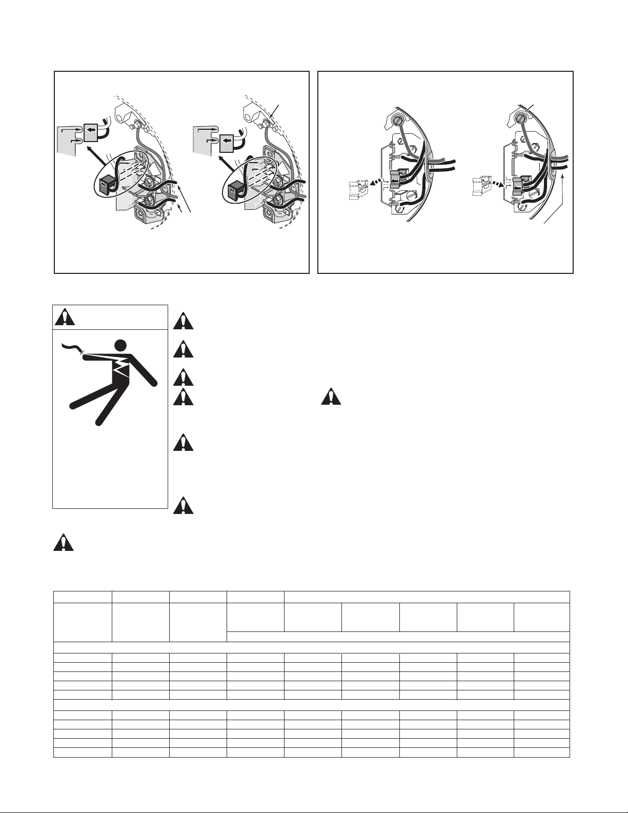
115 V
230 V
230 Volt to 115 Volt Conversion. Move plug to change voltage.
A
L1
230
Volts
115
Volts
230 Volt to 115 Volt Conversion. Move plug to change voltage.
Pull plug
straight
out from
terminal
board;
1.
1.
2.
2.
Plug in again
with arrow
on plug
pointing to
'115 Volts'.
Ground
Screw
A
L1
230
Volts
115
Volts
Clamp the power cable to prevent
strain on the terminals.
Ground
Screw
Clamp the power cable to prevent
strain on the terminals.
Connect the green (or bare copper)
ground wire to the grounding screw.
Connect the green (or bare copper) ground
wire to the green ground screw.
230V
115V
230V
115V
A
A
L2
L2
L1
L1
230V
115V
A
A
L2
L2
L1
L1
230V
115V
Power Supply
Wires
Figure 3 – Wiring Connection Diagram.
ELECTRICAL
Motor Terminal Block Wiring (as viewed from rear of motor, canopy removed)