IUH-F117-V1-*
Contents
2012-09
3
1 Introduction......................................................................... 5
2 Declaration of Conformity ................................................. 6
3 Safety................................................................................... 7
3.1 Symbols relevant to safety ............................................................................7
3.2 Intended Use ................................................................................................7
3.3 General notes on safety.................................................................................8
4 Product Description ........................................................... 9
4.1 UHF general .................................................................................................9
4.1.1 Advantages of UHF ..................................................................................9
4.1.2 Permissible Operating Capacity of UHF ...................................................9
4.1.3 Permissible Frequency Range of UHF......................................................9
4.1.4 Applications for UHF systems...................................................................9
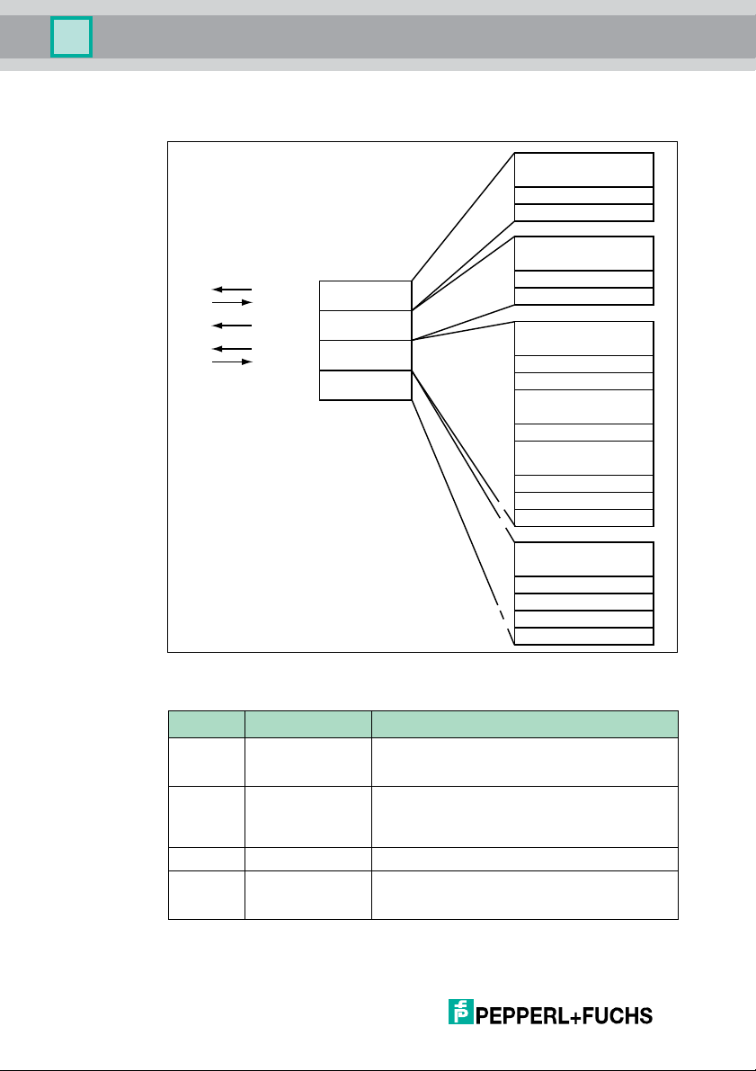
4.1.5 Memory Structure of a Tag in Accordance with ISO 18000-6C/
EPC Class 1 Gen 2 .................................................................................10
4.1.6 Electronic product code EPC .................................................................11
4.1.7 Unique numbering as per ISO ................................................................12
4.1.8 Influence of various materials on the sensing range ...............................13
4.1.9 Countries of Use.....................................................................................14
4.1.10 Dense Reader Mode DRM .....................................................................14
4.1.11 Europe....................................................................................................15
4.1.12 China......................................................................................................15
4.1.13 USA........................................................................................................16
4.1.14 RFID Frequency Bands ..........................................................................16
4.1.15 Relevant UHF standards ........................................................................16
4.2 General Functions and Features..................................................................17
4.3 Indicators and Controls ...............................................................................17
4.4 Connection .................................................................................................18
4.5 Scope of Delivery........................................................................................18
4.6 Accessories ................................................................................................18
4.6.1 IDENTControl .........................................................................................18
4.6.2 Read/Write Tags .....................................................................................19
4.6.3 Connection cable for R/W heads and trigger sensors ............................19
4.6.4 Cable connectors for the power supply ..................................................20
4.6.5 Installation accessories ..........................................................................20