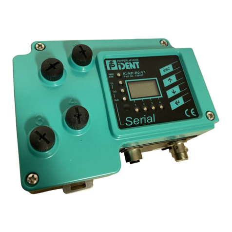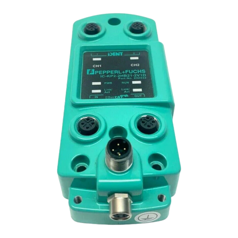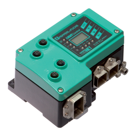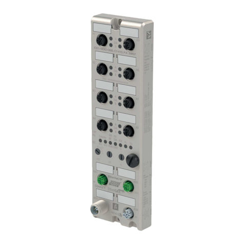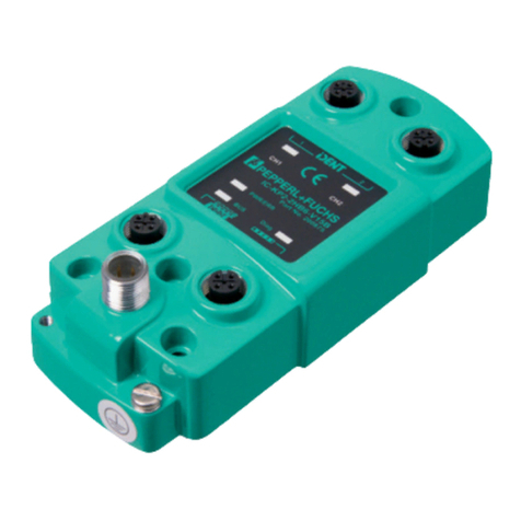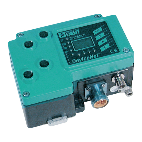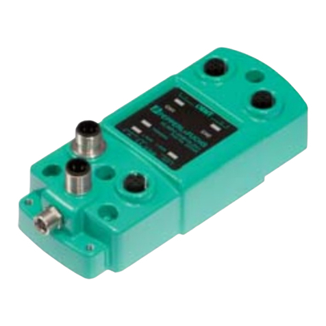
IC-KP-B6-V15B
Contents
2012-03
3
1 Introduction......................................................................... 5
2 Declaration of conformity .................................................. 6
2.1 Declaration of conformity ..............................................................................6
3 Safety................................................................................... 7
3.1 Symbols relevant to safety ............................................................................7
3.2 Intended use .................................................................................................7
3.3 General notes on safety.................................................................................7
3.4 Contact protection.........................................................................................8
4 Product Description ........................................................... 9
4.1 Range of application .....................................................................................9
4.2 Device characteristics ...................................................................................9
4.3 Product family ...............................................................................................9
4.3.1 R/W heads ...............................................................................................9
4.3.2 Code / Data carrier .................................................................................10
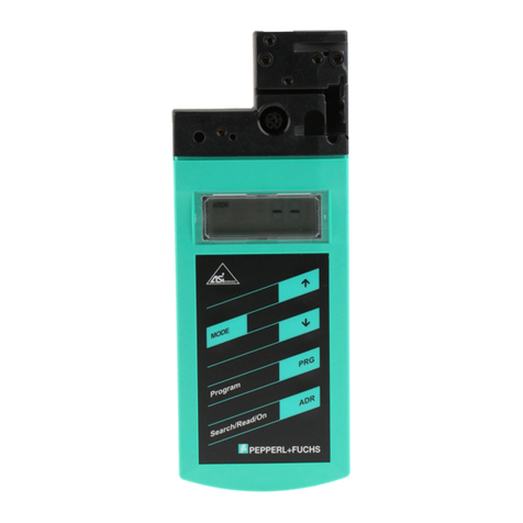
4.3.3 Handhelds ..............................................................................................10
4.4 Displays and controls..................................................................................11
4.5 Interfaces and connections .........................................................................12
4.6 Delivery package ........................................................................................12
4.7 Connection accessories..............................................................................13
4.7.1 Connection cable for R/W heads and trigger sensors ............................13
4.7.2 Cable connectors for the power supply ..................................................14
4.7.3 Connection cable to the PROFIBUS DP interface ..................................14
5 Installation......................................................................... 16
5.1 Storage and transport .................................................................................16
5.2 Unpacking...................................................................................................16
5.3 EMC concept ..............................................................................................16
5.4 Device connection ......................................................................................17
5.4.1 Power supply ..........................................................................................17
5.4.2 Read/Write Head and Trigger Sensors ...................................................17
5.4.3 Cable length between control interface and R/W heads .........................18
5.4.4 Ground connection.................................................................................18
5.4.5 PROFIBUS connection guide .................................................................18
5.4.6 Cables ....................................................................................................19
5.4.7 Transfer rates and line lengths ................................................................20
5.4.8 Terminator ..............................................................................................20
