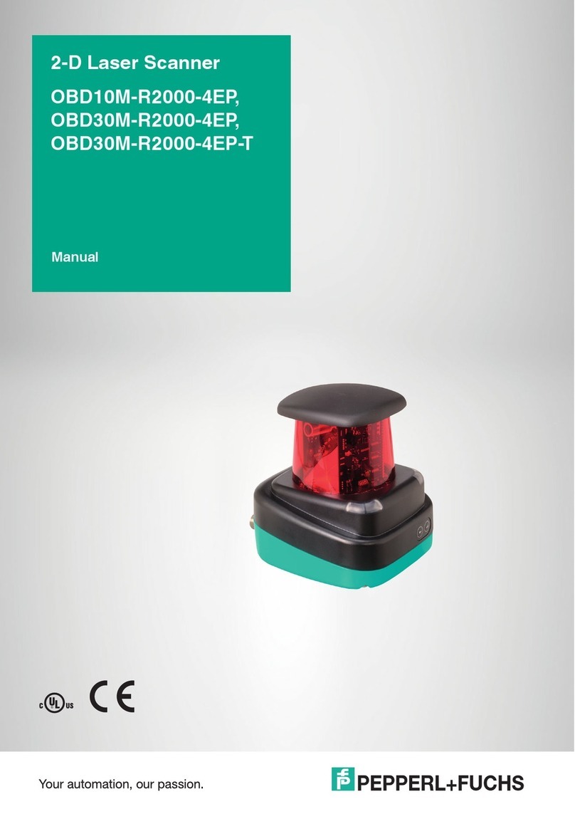
Pepperl+Fuchs OBD10M-R2000-4EP User manual

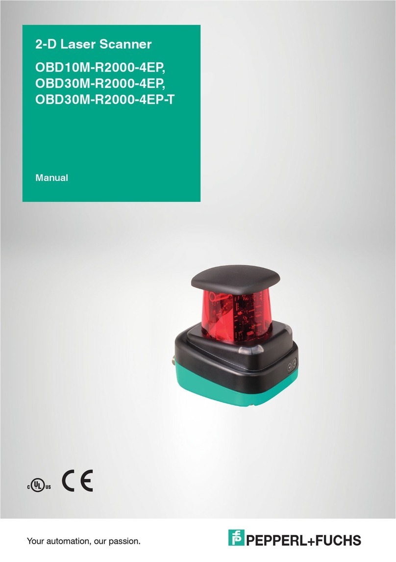
2-D Laser Scanner
OBD10M-R2000-4EP
OBD30M-R2000-4EP
OBD30M-R2000-4EP-T
OBD10M-R2000-4EP
OBD30M-R2000-4EP
OBD30M-R2000-4EP-T
EN
DE
FACTORY AUTOMATION
MANUAL

With regard to the supply of products, the current issue of the following document
is applicable: The General Terms of Delivery for Products and Services of the Elec-
trical Industry, published by the Central Association of the Electrical Industry (Zen-
tralverband Elektrotechnik und Elektroindustrie (ZVEI) e.V.) in its most recent
version as well as the supplementary clause: "Expanded reservation of proprietor-
ship"
Es gelten die Allgemeinen Lieferbedingungen für Erzeugnisse und Leistungen der
Elektroindustrie, herausgegeben vom Zentralverband Elektroindustrie (ZVEI) e.V.
in ihrer neusten Fassung sowie die Ergänzungsklausel: "Erweiterter Eigentumsvor-
behalt".
EN
DE
2-D Laser Scanner

2-D Laser Scanner
Contents
2016-03
1
EN
1 Introduction......................................................................... 2
1.1 Purpose of this quick start guide ...................................................................2
1.2 Product documentation on the internet..........................................................2
1.3 Intended Use ................................................................................................2
1.4 Validity ..........................................................................................................2
2 Safety................................................................................... 3
2.1 Laser Class 1 ................................................................................................3
3 Product Description ........................................................... 4
3.1 Indicators and Operating Controls ................................................................4
3.2 Interfaces and Connections ..........................................................................4
3.3 Included in Delivery.......................................................................................5
3.4 Accessories ..................................................................................................6
3.5 Further Information........................................................................................6
4 Installation........................................................................... 7
4.1 Mounting.......................................................................................................7
4.2 Device Connection........................................................................................8
5 Commissioning................................................................... 9
5.1 Ethernet Configuration ..................................................................................9

2016-03
2 - EN
2-D Laser Scanner
Introduction
EN
1Introduction
1.1 Purpose of this quick start guide
This quick start guide contains basic instructions for operating the device.
However, the manual takes priority over the quick start guide.
1.2 Product documentation on the internet
You can view all the relevant documentation and additional information on your
product at http://www.pepperl-fuchs.com. Simply enter the product name or
model number in the Product/Key word search box and click Search.
Select your product from the list of search results. Click on the information you
require in the product information list, e.g., Technical documents.
A list of all available documents is displayed.
1.3 Intended Use
The R2000 laser scanners are measuring devices that are used on automated
transport systems or other movable machinery in intralogistics. They are also
used on stationary equipment in the area of factory and building automation.
Make sure that the devices are used only for their intended purpose.
1.4 Validity
This manual applies to devices from firmware 1.20 and hardware 1.00 onward.
The versions can be found in the device menu; .
For devices with older versions, documentation is available on request.

2-D Laser Scanner
Safety
2016-03
EN - 3
EN
2Safety
2.1 Laser Class 1
Class 1 Laser Product
This sensor is certified according to laser protection class 1.
Warning!
Class 1 laser light
The laser light can be an irritant, especially in a dark environment. Do not point
lasers at people!
Maintenance and repairs should only be carried out by authorized service
personnel!
Install the device so that the warning is clearly visible and readable.
Caution: Use of controls, adjustments, or performance of procedures other than
those specified herein may result in harmful laser beam exposure.

2016-03
4 - EN
2-D Laser Scanner
Product Description
EN
3 Product Description
3.1 Indicators and Operating Controls
Figure 3.1 Indicators and Controls
3.2 Interfaces and Connections
The following connections are found on all devices:
Power Supply
There is a 4-pin M12 connector on the rear of the housing to connect the power
supply. The following diagram shows the pinning:
Figure 3.2 Power supply connection layout
No. Designation Color
1Operating status indicator Green
2Error indicator Red
3"Next" menu button
4"Return" menu button
5Q2—input/output 2 Ye l l o w
6Q1—input/output 1 Ye l l o w
7Laser face
8Ethernet link indicator Green
9Ethernet activity indicator Ye l l o w
Table 3.1 Indicators and Operating Controls
2
6
1
4
3
5
7
9
8
124 V power supply
2I/Q2
3Ground (GND)
4I/Q1
1
3
4
2

2-D Laser Scanner
Product Description
2016-03
EN - 5
EN
MultiPort
An 8-pin M12 connector is located on the rear of the housing. Inputs/outputs 3
and 4 are located here
All pins with "DNC (Do not connect)" must not be connected!
Interface:
There is a 4-pin M12 socket on the back of the housing to connect the Ethernet
interface. The following diagram shows the pinning:
Figure 3.3 Ethernet connection layout
The connector housing is located on the shield.
3.3 Included in Delivery
The delivery package contains:
■R2000 2D laser scanner
■Quick start guide
■Protective cover for MultiPort and Ethernet
■3 x socket cap screws, M5 x 10
■3 x washers, size 5
1DNC (Do not connect)
2DNC (Do not connect)
3DNC (Do not connect)
4I/Q3
5I/Q4
6DNC (Do not connect)
7DNC (Do not connect)
8DNC (Do not connect)
1TD+
2RD+
3TD-
4RD-
1
4
6
7
8
53
2
1
3
42

2016-03
6 - EN
2-D Laser Scanner
Product Description
EN
3.4 Accessories
The following products are available as accessories.
3.5 Further Information
Further product information and technical data are available at www.pepperl-
fuchs.com.
Designation Description
V1SD-G-2M-PUR-ABG-V45-G Patch cable M12 to RJ45, length 2 m
V1SD-G-5M-PUR-ABG-V45-G Patch cable M12 to RJ45, length 5 m
V1SD-G-ABG-PG9 Single-ended male cordset, M12 D-coded, 4-pin for bus cable
V1-G-2M-PUR Single-ended female cordset, straight, M12, 4-pin, PUR cable,
length 2 m
V1-G-5M-PUR Single-ended female cordset, straight, M12, 4-pin, PUR cable,
length 5 m
V1-W-2M-PUR Single-ended female cordset, angled, M12, 4-pin, PUR cable,
length 2 m
V17-G-2M-PUR Single-ended female cordset, straight, M12, 8-pin, shielded,
PUR cable, length 2 m
V17-G-5M-PUR Single-ended female cordset, straight, M12, 8-pin, shielded,
PUR cable, length 5 m
V1S-B Blind plugs
Note!
Installation Information for North America
If a connection is made with the M12 multi-pin connector, then in the final
installation of the power supply, the product must be used with a UL-listed
cable/connector assembly (CYJV) that is designed for at least 30 VDC and at least
1.0 A.
Designation Description
V1-G-BK-2M-PUR-U Single-ended female cordset, straight, M12, 4-pin, PUR cable, length 2 m,
"UL recognized"
V1-G-BK-5M-PUR-U Single-ended female cordset, straight, M12, 4-pin, PUR cable, length 5 m,
"UL recognized"
V1-G-BK-10M-PUR-U Single-ended female cordset, straight, M12, 4-pin, PUR cable, length 10 m,
"UL recognized"
2-D Laser Scanner
Installation
2016-03
EN - 7
EN
4 Installation
4.1 Mounting
The device can be fitted with the supplied socket head screws with washers on
the underside of the device.
Figure 4.1 Dimensional drawing R2000
Caution!
Safety information
Do not point the sensor into the sun.
Protect the sensor against direct and prolonged sunlight.
Prevent condensation from forming by ensuring that the sensor is not subjected to
any major temperature fluctuations.
Do not subject the sensor to aggressive chemicals.
Keep the glass on the device clean.
For cleaning, use only water (if necessary with a little detergent) and a soft
microfiber cloth! The use of other detergents is not permitted! The glass must
never be cleaned when dry!
Caution!
Screw-in depth
The maximum screw-in depth in the base must not exceed 8 mm, otherwise the
device will be mechanically destroyed! The minimum screw-in depth is 5 mm.
70
(40)20
60
20
53
106
117.5
4658
116.5
106
16
97.1
3 x M5
20
45
Emitter range and receiver range
Complieswith 21 CFR
1040.10and 1040.11except
for deviation spurs uantto
Laser Noti ce No. 50,
dated Jun e 24, 2007
CLASS 1
LASER PRODUCT
IEC60825-1:2007 certified.

2016-03
8 - EN
2-D Laser Scanner
Installation
EN
4.2 Device Connection
Electrical connection in line with IP65
Put protective covers on unused M12 connectors.
The IP65 protection class is achieved. The protective covers can be ordered
as accessories .
The device conforms to protection class III. This means that the power has to be
supplied as a low protective voltage (PELV).
The power supply of the device is 10 VDC ... 30 VDC. On account of the
integrated motor, an increased level of startup current is required compared with
normal operation. It is recommended that power supplies with 1 A (at 24 V) or with
2 A (at 12 V) are used.
The maximum cable length is 30 m.
The pin assignment is as follows:
Figure 4.2 R2000 pin assignment
Note!
Keep the emitting/receiving area clear
During assembly, make sure that the emitting/receiving area is kept clear. If the
emitting/receiving area is covered, this reduces the performance of the 2D laser
scanner.
PowerMultiportEthernet
4
1
2
3
TD+
TD-
RD-
Shield
4
1
2
3
24 V DC
0 V DC
RD+ I/Q2
I/Q1
4
1
2
3
DNC
DNC
DNC
I/Q3
7
5
6DNC
I/Q4
DNC
8DNC
DNC = Do not connect
1
3
4
2
1
3
42
1
4
6
7
8
53
2

2-D Laser Scanner
Commissioning
2016-03
EN - 9
EN
5 Commissioning
1. Connect the device to the power supply.
The initialization phase lasts approx. 10 seconds. This phase is indicated
by an illuminated Power LED. The display is still disabled in this phase.
2. There is another initialization phase that lasts approx. 10 seconds.
The display turns on and shows circles moving downward.
3. After the initialization phase, the Pepperl+Fuchs logo will appear.
The device is ready for operation.
To achieve the best measurement accuracy, allow the device to warm up for 30
minutes. The sensor has been tested and calibrated before delivery. It can be put
into operation immediately. It is generally recommended to use a dedicated
network card for the connection to the device. For parameterization, connect the
device to an Ethernet interface on a computer. Install the PACTware software and
the appropriate DTM.
5.1 Ethernet Configuration
The device has three different address modes. Select your preferred mode from
the modes described below. The setting is configured directly on the device using
the menu interface.
Auto IP
In this mode, the device independently selects a "Link-Local" IP address in the
169.254.0.0/16 range. During this process, measures are taken to ensure that the
selected address is not already being used by another device.
The device is configured to Auto IP by default. The Auto IP setting is the ideal way
to establish a direct connection to a PC. Set the DHCP mode (Dynamic Host
Configuration Protocol) on the PC. To do this, select the TCP/IP protocol in the
network card properties and select the "Obtain an IP address automatically"
setting there. After approx. 30 seconds, Windows assigns an Auto IP for the PC.

2016-03
10 - EN
2-D Laser Scanner
Commissioning
EN
DHCP
Set the device to DHCP under the "Address mode" menu item. The DHCP
configuration requires a DHCP server in the local network, e.g., a router. See the
"Auto IP" item for information on this.
Manual IP
Set the device to manual under the "Address mode" menu item. The IP address is
set to 10.0.10.9 and the subnet mask to 255.0.0.0 by default. To connect the
device to the PC, the network card must be configured as follows.
Set the required IP address in the network card menu. Select the TCP/IP protocol
in the network card properties and select the "Use the following IP address"
setting there. Enter the required IP address and subnet mask.
Note!
Device restart
You must restart the device after changing the Ethernet configuration.

Subject to modifications
Copyright PEPPERL+FUCHS • Printed in Germany
www.pepperl-fuchs.com
FACTORY AUTOMATION –
SENSING YOUR NEEDS
Worldwide Headquarters
Pepperl+Fuchs GmbH
68307 Mannheim · Germany
Tel. +49 621 776-0
E-mail: [email protected]
USA Headquarters
Pepperl+Fuchs Inc.
Twinsburg, Ohio 44087 · USA
Tel. +1 330 4253555
E-mail: [email protected]
Asia Pacific Headquarters
Pepperl+Fuchs Pte Ltd.
Company Registration No. 199003130E
Singapore 139942
Tel. +65 67799091
E-mail: [email protected]
DOCT-3777C
03/2016
Other manuals for OBD10M-R2000-4EP
1
This manual suits for next models
2
Table of contents
Other Pepperl+Fuchs Scanner manuals

Pepperl+Fuchs
Pepperl+Fuchs EX-DRAGON-M101 User manual

Pepperl+Fuchs
Pepperl+Fuchs IDM-Z2-160-D-1D-J2-SU-N-N0 User manual

Pepperl+Fuchs
Pepperl+Fuchs IDM-Z2-164-D-1D-J2-SU-P-N0 User manual

Pepperl+Fuchs
Pepperl+Fuchs OBD30M-R2000-4EP User manual

Pepperl+Fuchs
Pepperl+Fuchs IDM161-M-1D-J1-BT-N-N0 User manual

Pepperl+Fuchs
Pepperl+Fuchs IDM-Z1-161-M-1D-J1-BT-N-N0 User manual

Pepperl+Fuchs
Pepperl+Fuchs IDENTControl IQH3-FP-V1 User manual

Pepperl+Fuchs
Pepperl+Fuchs OMD10M-R2000-B23 User manual

Pepperl+Fuchs
Pepperl+Fuchs OMD10M-R2000-B23 User manual

Pepperl+Fuchs
Pepperl+Fuchs OBD10M-R2000-4EP User manual