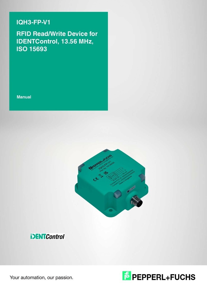
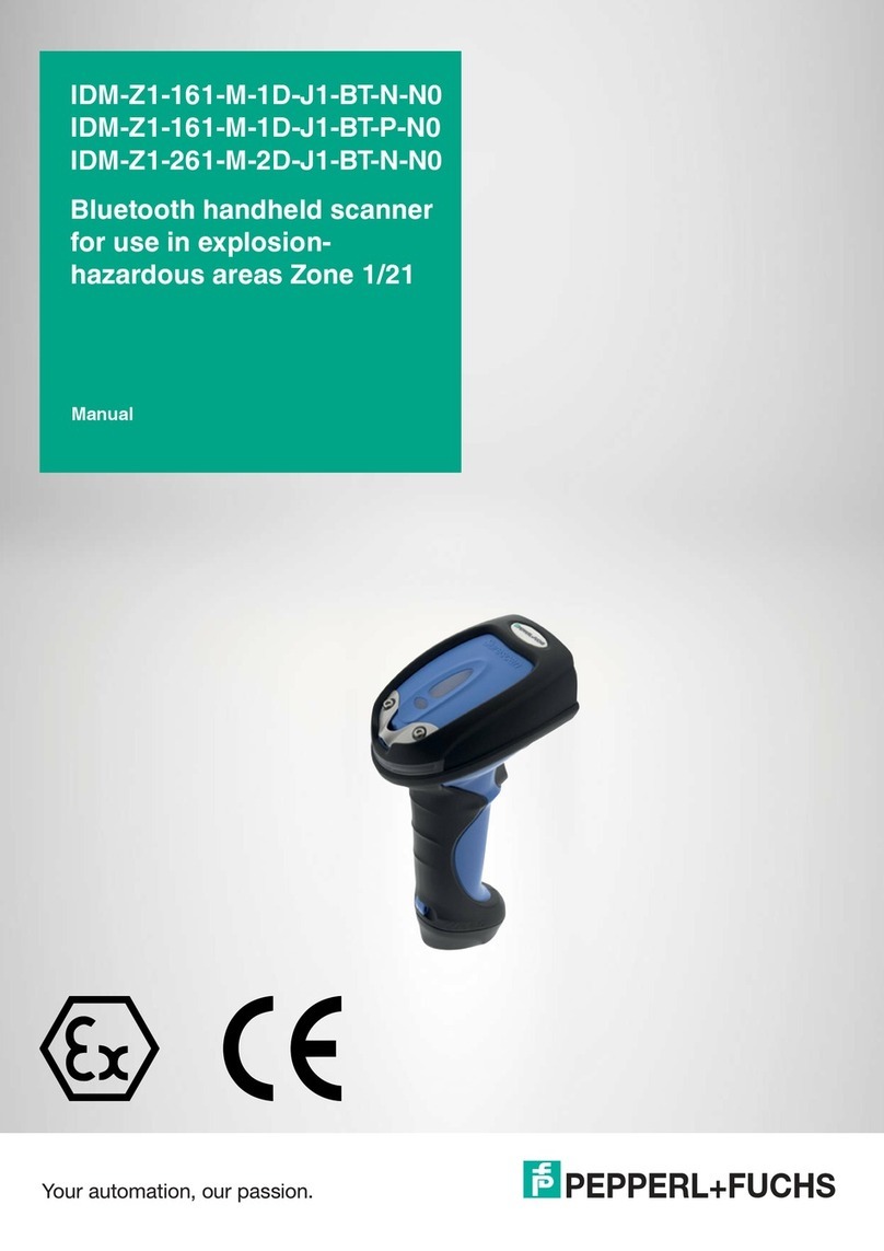
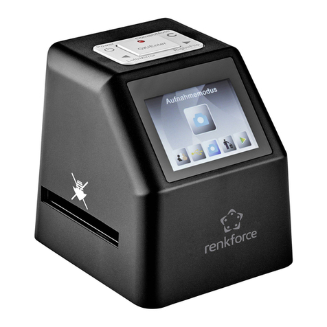
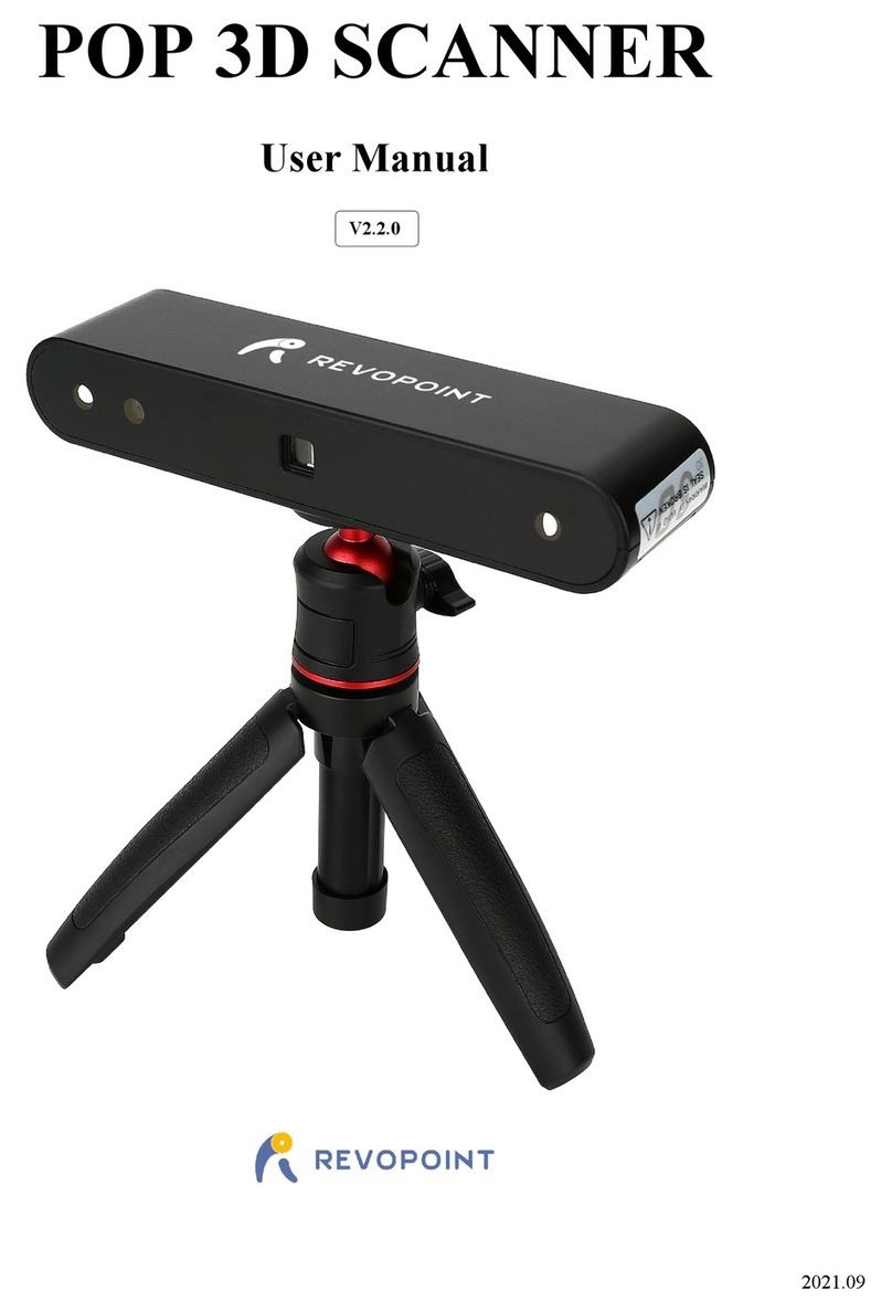
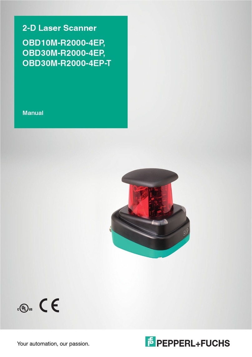
Pepperl+Fuchs IDM161-M-1D-J1-BT-N-N0 User manual

Manual
IDM161-M-1D-J1-BT-N-N0
IDM261-M-2D-J1-BT-N-N0
Bluetooth handheld scanner for use in explosion-
hazardous areas Zone 1/21


The latest version of the General Terms of Supply for Products
and Services in the Electronics Industry set out by the German
Electrical and Electronic Manufacturers’ Association (ZVEI) and
the "Extended Reservation of Proprietorship" supplementary
clause apply to this document.

Table of Contents
1. Important Notes About The Instruction Manual..................................6
1.1. Safety Information.......................................................................................... 6
1.2. Notes About The Manual ............................................................................... 7
1.3. General Warning Messages...........................................................................9
2. Technical Data.......................................................................................12
2.1. Explosion Protection....................................................................................12
2.2. Technical Data for Bluetooth Scanner .........................................................12
2.3. Use ..............................................................................................................13
3. System Structure..................................................................................14
3.1. Overview......................................................................................................14
3.2. System Structure 1 ...................................................................................... 15
3.3. System Structure 2 ...................................................................................... 16
3.4. System Structure 3 ...................................................................................... 17
4. Commissioning.....................................................................................18
4.1. Preparing Bluetooth Handheld Scanners.....................................................18
4.2. Pinout of Power Module with RS232 ...........................................................22
4.3. Pinout of power module with USB................................................................ 25
5. Accessories ..........................................................................................28
4
Table of ConTenTs
2018-06


1. Important Notes About The
Instruction Manual
1.1.Safety Information
This document contains symbols to identify warning messages and information mes-
sages.
Warning messages
You always nd warning messages whenever hazards could result from your actions.
It is essential that you observe these warning messages to ensure your personal safe-
ty and to prevent property damage.
Warning messages are shown in descending order according to the risk level, as
follows:
DANGER!
This symbol warns you of an immediate and present danger.
If you do not observe this warning message, there is a risk of personal injury and
even death.
WARNING!
This symbol warns you of a potential fault or hazard.
If you do not observe this warning message, there is a risk of personal injury or
severe property damage.
CAUTION!
This symbol warns you of a potential fault.
Failure to observe this warning message may result in the product or any systems
and plants connected to it malfunctioning or suering a complete failure.
6
ImporTanT noTes abouT The InsTruCTIon manual
2018-06

Information messages
Note
This symbol draws your attention to important information.
Example
This symbol indicates an example.
Tip
This symbol indicates a tip is provided.
Action
This symbol highlights an action.You are prompted to perform an action or sequence
of actions.
1.2.Notes About The Manual
Please read the manual carefully before initial commissioning.
The instruction manual contains important information on the function and safety
regulations. If you do not observe this information, the intended use in explosion-haz-
ardous areas cannot be guaranteed.
Observe the information given in this manual during commissioning and use of the
product.
There is no responsibility for actuality. Pepperl+Fuchs GmbH reserves the right to
make changes to this document.
Prior to use, make sure that you have the latest version of the user manual. Check the
homepage www.pepperl-fuchs.com or contact your contact person at Pepperl+Fuchs
for clarication.
The gures in this manual are for illustration purposes only, and may dier from the
actual design in its appearance.
7
ImporTanT noTes abouT The InsTruCTIon manual
2018-06

DANGER!
Do not make any changes to the device that are not intended or been approved by
Pepperl+Fuchs.
Improper handling of the handheld scanner can void the type approval to operate in
explosion-hazardous areas.
Non-compliance excludes warranty claims.
Note
Information regarding programming from the SICK AG manual (www.SICK.com) is
required for the full commissioning of the handheld scanner.
8
ImporTanT noTes abouT The InsTruCTIon manual
2018-06

1.3.General Warning Messages
WARNING!
Only operate the devices when assembled.
Do not clean the device in explosion-hazardous areas. Do not wipe it dry.
Switch o the device immediately if you believe that the device can no longer be
operated safely after damaging eects or abnormalities in general (ingress of
water, uids, exposure to temperatures outside the specied range etc.).
Note general statutory regulations or directives on occupational safety, accident
prevention regulations and environmental protection laws, e.g., Ordinance on
Industrial Safety and Health (BetrSichV).
Do not open the device.
You may not make any changes to the device.You may not exchange or replace
any components. Explosion protection is no longer guaranteed for non-speci-
ed components.
Ensure safe handling during use through adequate stability and freedom of
movement.
Immediately remove the device from the explosion-hazardous area in the event
of damage to the housing.
IEC 60079-19 and IEC 60079-17 stipulate that you as the operator of electrical
plants in explosion-hazardous areas are obligated to appoint an electrician to
check that these plants are in perfect condition.
Do not insert any objects into the housing or other openings of the handheld
scanner. Openings on the device must not be obstructed, blocked, or covered.
Dispose of the device and the associated components correctly, as required by
law, by an approved company.
Note
Note the relevant deployment and operational regulations for electrical plants
(e.g., Directive 99/92/EC, Directive 2014/34/EU or the applicable national regula-
tions, IEC 60 079-14, and the series DIN VDE 0100).
As the operator, perform maintenance and repair work for the device properly in
explosion-hazardous areas.
9
ImporTanT noTes abouT The InsTruCTIon manual
2018-06

WARNING!
Devices equipped with lasers comply with the standards US 21 CFR 1040.10 and
EN 60825-1. The classication of the laser device is specied on a plate attached
to the device. Class 1 laser devices are not considered to be hazardous under the
intended use.
Nevertheless, do not look directly into the light source.
The following statement is required by American and international laws:
The use of control elements, adjustments, or the use of procedures that do not
follow the instruction described here, may lead to hazardous radiation exposure.
Class 2 laser devices work with a visible low-voltage LED. As with any bright light
source, such as the sun, the operator should not look directly into the light beam. A
class 2 laser is considered harmless for short-term exposure.
Maintenance
No ongoing maintenance is required when the mounting instructions, the ambient
conditions and proper operation are observed.
Inspection
The operator must appoint an electrician to check an electrically powered device in
explosion-hazardous areas, to ensure it is in correct condition (IEC 60079-19 and IEC
60079-17).
Repairs
Repairs may only be performed by the manufacturer or persons commissioned and
trained for this purpose.
WARNING!
The device is factory-sealed. It may be opened only by trained and qualied per-
sonnel at the factory.
Software installation
Instructions relating to software installation on the PC can be found in the SICK AG
manual.
Commissioning
Before you put the device into operation, check whether all the necessary compo-
nents are available.
10
ImporTanT noTes abouT The InsTruCTIon manual
2018-06
2. Technical Data
2.1.Explosion Protection
II 2G Ex ib IIB T4
II 2G Ex ib IIB T4 Gb
II 2D Ex ib IIIC T135°C
II 2D Ex ib IIIC T135°C Db
Test certicate
IBExU18ATEX1050
IECEx IBE 18.0009
Manufacturer
Pepperl+Fuchs GmbH
Lilienthalstraße 200
68307 Mannheim, Germany
info@de.pepperl-fuchs.com
2.2. Technical Data for Bluetooth Scanner
IDM161-M-1D-J1-BT-
N-N0
IDM161-M-1D-J1-BT-
P-N0
IDM261-M-2D-J1-BT-
N-N0
Description Linear imager 2-D imager
Barcode One-dimensional 1-D
(barcode) One-dimensional 1-D
(Barcode and stacked
code incl. PDF417)
One-dimensional 1-D &
2-D
(Barcode and stacked
code incl. PDF417)
Barcode types Code 39, Code 39 Trioptic, Code 32, Code 93, Code 11, Codabar, Code 128,
GS1-128 / EAN 128, UPC / EAN / JAN (with addition), MSI/Plessey, UK/Plessey,
IATA, Interleaved 2 of 5, Standard and Industrial 2 of 5, Matrix 2 of 5, Telepen, GS1
DataBar, Australian Post, China Post, German Post, US Planet, US Postnet, British
Post, Intelligent Mail, Japan Post, Korean Post, Dutch KIX Post
Stacked codes - PDF417, MicroPDF417, Code 49, Code 16K, Com-
posite, Codablock F
2-D code types - Data Matrix, QR code,
MicroQR-Code, Aztec,
MaxiCode
Light source LED, visible red light (630 nm)
11
TeChnICal DaTa
2018-06
TeChnICal DaTa

IDM161-M-1D-J1-BT-
N-N0
IDM161-M-1D-J1-BT-
P-N0
IDM261-M-2D-J1-BT-
N-N0
Scan frequency 500 Hz 60 Hz
Reading dis-
tance 20 mm ... 850 mm 30 mm ... 160 mm
Code resolution Approx. ≥ 0.076 mm Approx. ≥ 0.13 mm
Immunity to
extraneous
light
100,000 lx
Electrical data
Current con-
sumption 330 mA (Standby 80/130 mA; Peak 500 mA)
Battery Lithium ion battery 3.6 V; 1500 mAh
Battery power Up to 60,000 scans at full battery charge
Feedback
Visual 2 x LED (operating state/read conrmation)
Acoustic Buzzer (can be switched o)
Ambient conditions
Shock resis-
tance 50 drop tests on concrete from a height of 2 m
Operating tem-
perature -20 °C to +50 °C
Storage tem-
perature -30 °C to +70 °C -40 °C to +70 °C
Relative humid-
ity 95 % non-condensing
Mechanical data
Degree of pro-
tection IP65
Dimensions [W
x H x D] 104 mm x 176 mm x 76 mm
Weight Approx. 260 g
2.3.Use
The handheld scanner is a piece of handheld apparatus.
It enables portable recording and direct data transfer of barcodes and 2-D codes
in explosion-hazardous areas. The device is specically modied for use in explo-
sion-hazardous areas of zone 1 and zone 21.
12
TeChnICal DaTa
2018-06
TeChnICal DaTa

3. SyStem Structure
3.1.Overview
The Bluetooth handheld scanners and their accessories are presented in the fol-
lowing overview. Charging the handheld scanner batteries can take place within the
hazardous area using the zone 1/21 certied base station/charging cradle and the
associated power module. Furthermore, the scanner can be charged in the safe area
using a base station/charging cradle.
Figure 1. Handheld scanner and accessories
In the following two chapters, the typical usage cases are described in more detail.
Non-Ex
Safe Area
Bluetooth
Scanner Connection cable Supply / Barrier VisuNet Device
1D Scanners
IDM161-M-1D-J1*
2D Scanner
IDM261-M-2D-J1*
USB
CBL-IDMx61-B-J1-U-*
RS232
CBL-IDMx61-B-J1-S-*
24 V DC, USB version
PSU-IDM160-BD-1D-J1-DC-U-N0
110/230 V AC, USB version
PSU-IDM160-BD-1D-J1-AC-U-N0
24 V DC, RS232/RS422 version
PSU-IDM160-BD-1D-J1-DC-S-N0
110/230 V AC, RS232/422
PSU-IDM160-BD-1D-J1-AC-S-N0
110/230 V AC, non-ex
PSU-IDMx61-BC-N0-N0
Base station &
Charger
Base Station &
Charger
IDMx61-B-J1-BT-N0
Base Station &
Charger
IDMx61-B-N0-BT-N0
Charger
IDMx61-C-N0-BT-N0
RM/PC-GXP1*00
via USB Ex e interface
RM/PC-GXP1*00
w/ RS232 Ex e option
RM/PC9xx series
via USB Ex e interface
RM/PC37xx series
via USB Ex e interface
RM/PC37xx series
via RS232 Ex e interface
RM/PC-GXP1*00
w/ BT interface option
Up to 5m cable
Up to 20m cable
RS232
CBL-IDMx61-B-N0-S-*
USB
CBL-IDMx61-B-N0-U-*
Bluetooth Scanners
Cable & Socket for AG* housing
DATL-IDM-DB-S-XX00-N0
RM/PC-GXP1*00
w/ RS232 Ex ioption
Preferred solution
Preferred solution
Host PC
13
sysTem sTruCTure
2018-06
sysTem sTruCTure

3.2.System Structure 1
Overview of the complete system structure 1: Bluetooth handheld scanners IDM161-
M1D-J1-BT-N-N0, IDM261-M-2D-J1-BT-N-N0, and base station connected to intrinsi-
cally safe RS232 Ex i interface VisuNet GXP.
RS232 Ex i
max. length 6m
RM-/PC-GXP1100*3*
RS232 Ex i interface option„3“ required!
CBL-IDMx61-D-J1-S*
RS232 cable
straight/coiled, different lengths
IDMx61-B-J1-BT-N0
Base Station & Charge
r
IDMx61-M*
2D or 1D Scanner,
Bluetooth
DATL-IDM-DB-S-XX00-N0
Cable & Socket for AG* housing
Figure 2. System structure 1—base station connected to RS232 Ex i interface GXP
Description:
The Bluetooth handheld scanner has been designed with the battery for explo-
sion-hazardous areas. For proper operation in explosion-hazardous areas, a ID-
Mx61-B-J1-BT-N0 base station, a CBL-IDMx61-B-J1* cordset, the DATL-IDM-DB-S-
XX00-N0 connection cable, and the RS232 Ex i interface option of the VisuNet GXP
are required.
Data is transferred this structure directly via the base station, which transfers the data
to the GXP via the intrinsically safe Ex i RS232 interface. Furthermore, communica-
tion in this structure can be realized via the Bluetooth interface option of the VisuNet
GXP.
The IDMx61-B-J1-BT-N0 base station can be used in both cases as a charging cradle
to charge the scanner in explosion-hazardous areas.
14
sysTem sTruCTure
2018-06
sysTem sTruCTure

3.3.System Structure 2
Overview of the complete system structure 2: Bluetooth handheld scanners IDM161-
M1D-J1-BT-N-N0, IDM261-M-2D-J1-BT-N-N0, and base station and power module in
explosion-hazardous areas.
AC/DC
Power supply
24 V DC
24 V DC or
110/230 V AC
PSU-IDM160-BD-1D-J1*
1D supply, USB/RS232,
AC or DC
CBL-IDMx61-B-J1*
USB/RS232 cable
straight/coiled, different lengths
RM-/PC-GXP1100*2*
Bluetooth Option in DPU IDMx61-M*
2D or 1D Scanner,
Bluetooth
IDMx61-B-J1-BT-N0
Basestation & Charger
Host PC
Option 1:
Connection to
HMI Sytem
Option 2:
Connection to
Base Station
Data (in case of option2)
USB / RS232
Figure 3. System structure 2–scanner with base station to barriers/Bluetooth option VisuNet GXP
Description:
The Bluetooth handheld scanner has been designed with the battery for explo-
sion-hazardous areas. For proper operation in explosion-hazardous areas a IDMx61-
B-J1-BT-N0 base station, a CBL-IDMx61-B-J1* cordset between the base station and
the PSU-IDM160-BD-1D-J1* power module, and a connection cable to the power
module are required.
Data can be transferred directly using a HMI system with Bluetooth interface (e.g.,
VisuNet GXP) (option 1) or using the base station, which can be connected to a host
PC via the power supply module and a data line (option 2).
In the case of option 1, the IDMx61-B-J1-BT-N0 base station can be used purely as a
charging cradle. A data line to a host PC is not needed in this case.
External connection lines:
Data lines USB: 0.2 – 2.5 mm2, 4-core or
RS232: 0.2 – 2.5 mm2 3-core
Supply line 0.2 – 2.5 mm2 3-wire
(see accessories in the appendix)
The Bluetooth handheld scanner, the base station, and the power module may be
connected and used in explosion-hazardous areas.The current rating of the connec-
tion line must be observed.
15
sysTem sTruCTure
2018-06

3.4.System Structure 3
Overview of the complete system structure 3: Bluetooth handheld scanner and
charging cradle in non-explosion-hazardous areas
IDMx61-M*
2D or 1D Scanner, Bluetooth
RM-/PC-GXP1100*2*
Bluetooth Option in DPU
IDMx61-B-N0-BT-N0
(IDMx61-C-N0-BT-N0)
Non-Ex Base Station
Or Charger
PSU-IDMx61-BC-N0-N0
Non-Ex AC/DC
Power supply
Host PC
Data (in case of option 2)
USB / RS232
Option 1:
Connection to
HMI Sytem
Option 2:
Connection to
Base Station
CBL-IDMx61-B-N0*
Non-Ex Data cable
RS232 / USB
Figure 4. System structure 3—scanner with a base station in the safe area/Bluetooth option VisuNet GXP
Description:
The Bluetooth handheld scanners can be used alone in explosion-hazardous areas;
the base station and charging cradle can be installed in the safe area.
Depending on the application, communication with a Bluetooth-enabled operator
workstation (e.g., VisuNet GXP) can be realized (option 1). In this case, it is possible
to use the IDMx61-C-N0-BT-N0 charging cradle in the safe area to charge the scan-
ner.
Instead of just the charging cradle, the non-explosion hazardous area base station ID-
Mx61-B-N0-BT-N0 can be used (option 2).This can be connected directly to a power
supply and a computer can be connected in the non-explosion hazardous area using
a RS232 or USB cable.
16
sysTem sTruCTure
2018-06

4. Commissioning
4.1. Preparing Bluetooth Handheld Scanners
DANGER!
The battery must not be changed or inserted in explosion-hazardous areas.
Improper handling can void the type approval.
Preparation of Bluetooth handheld scanners
1. The battery compartment is located on the underside of the Bluetooth handheld
scanner. Loosen the screw with a suitable tool to remove the cover. After loosening
the screw, some force is required to remove the cover
Figure 5. Removing the battery compartment lid
2. The battery is required to commission the Bluetooth handheld scanner. The protec-
tive cap must be removed before inserting the battery into the handheld scanner.
Figure 6. Removing the protective battery cap
17
CommIssIonIng
2018-06
CommIssIonIng

DANGER!
The designated battery may only be used!
3. The battery is inserted into the compartment on the handheld scanner. The end of
the pull tab must be seen protruding out of the opening of the handheld scanner. If
the battery is inserted correctly and connected to the contacts, there is an audible
and visual signal. The opening must be completely sealed again. Before commissi-
oning, check whether the screw cap has been properly sealed.
Figure 7. Inserting the battery and closing the protective cap
Using the base station in explosion-hazardous areas—system
structure 1
1. The cordset from the base station to the power module is plugged into the opening
at the bottom of the base station is plugged in. An audible click can be heard when
the cable is fully inserted. It must be veried that the cable is rmly anchored.
Figure 8. Connecting the RJ45 cable to the base station
18
CommIssIonIng
2018-06
CommIssIonIng

2. The plug of the cordset is connected to the power module plug coupling. Ensure
that the connection is fully secured to the screw cap after plugging together.
Figure 9. Connecting the plug coupling to the power module basic connection line
3. The handheld scanner is placed in the charger. The underside of the handle is used
rst to ensure that the charging contacts are properly connected. The LED light on
the scanner head indicates successful charging.
Figure 10. Inserting the scanner into the base station
19
CommIssIonIng
2018-06

Using the base station in non-explosion hazardous areas - sys-
tem structure 2
1. With a non-explosion-protected base station, charging in non-explosion hazardous
areas can be performed using the PSU-IDMx61-BC-N0-N0 power supply. The ca-
ble is plugged into the opening for this at the bottom of the base station. For a base
station for explosion-hazardous areas, this connection is sealed at the factory.
Figure 11. Connecting the power supply for the non-explosion-hazardous base station
2. To connect in the non-explosion-protected area, the cable to connect to the power
supply and to the PC is inserted into the opening for this at the bottom of the base
station. An audible click can be heard when the cable is fully inserted. It must be
veried that the cable is rmly anchored.
Figure 12. Connecting the RJ45 cable to the base station
20
CommIssIonIng
2018-06
This manual suits for next models
1
Table of contents
Other Pepperl+Fuchs Scanner manuals

Pepperl+Fuchs
Pepperl+Fuchs OMD10M-R2000-B23 User manual

Pepperl+Fuchs
Pepperl+Fuchs ODT-HH-MAH300 User manual

Pepperl+Fuchs
Pepperl+Fuchs IDENTControl IQH3-FP-V1 User manual

Pepperl+Fuchs
Pepperl+Fuchs IDM-Z2-160-D-1D-J2-SU-N-N0 User manual

Pepperl+Fuchs
Pepperl+Fuchs PROSCAN/38a User manual

Pepperl+Fuchs
Pepperl+Fuchs IDM-Z2-164-D-1D-J2-SU-P-N0 User manual

Pepperl+Fuchs
Pepperl+Fuchs OBD30M-R2000-4EP User manual

Pepperl+Fuchs
Pepperl+Fuchs OMD10M-R2000-B23 User manual

Pepperl+Fuchs
Pepperl+Fuchs OBD10M-R2000-4EP User manual

Pepperl+Fuchs
Pepperl+Fuchs IDM-Z1-161-M-1D-J1-BT-N-N0 User manual