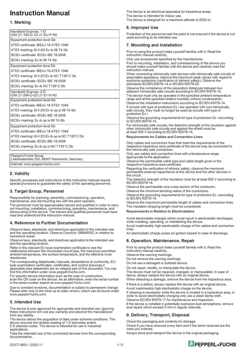
Pepperl+Fuchs EX-DRAGON-M101 User manual

EXDragM101_V114_TH_E.doc / 30.09.09
Technical Manual
Ex Scanner EX-DRAGON-M101
EXOM-DRAGON

ExDragM101_V114_TH_E.doc/ 05/10/2009/ - 1 -
Inhaltsverzeichnis
1Important information......................................................................................................4
1.1 General instructions ..................................................................................................................................4
1.2 Safety instructions.....................................................................................................................................5
1.3 Symbols used in this manual ....................................................................................................................6
2Laser Safety Conditions:.................................................................................................7
3System Display in Hazardous Area................................................................................8
4Operation........................................................................................................................10
4.1 Preparing the Hardware..........................................................................................................................10
4.2 Special conditions for apparatus, category 3D (in zone 22) ...................................................................11
5EX-DRAGON-M101 Radio Scanner...............................................................................12
6Introduction....................................................................................................................13
6.1 EX-DRAGON-M101 Laser Scanners.....................................................................................................13
6.1.1 Description And Use ........................................................................................................................13
6.1.2 Reading Diagram.............................................................................................................................14
6.1.3 EX-DRAGON-M101 Indicators ........................................................................................................14
6.1.4 Housing............................................................................................................................................15
6.1.5 EX-DRAGON-M101-10....................................................................................................................16
6.2 EXOM-DRAGON Cradle.........................................................................................................................17
6.2.1 Technical Data EXOM-DRAGON ...................................................................................................17
6.3 LD DRAGON Charger.............................................................................................................................18
6.3.1 LD DRAGON Indicators...................................................................................................................18
6.4 PG12-10 Mains adapter* ......................................................................................................................19
6.4.1 PG12-10 Technical data ..................................................................................................................19
7System Configuration....................................................................................................20
7.1 System Start-Up......................................................................................................................................20
7.1.1 Connecting the Cradle to a Host (PC) system by ENT-DC .............................................................20
7.1.2 Connecting the Cradle to a Host (PC) system by TERMEX 2xx / 3xx ............................................21
7.1.3 Connecting the cradle to a Host (PC) system by iPC-EX................................................................21
7.1.4 Schematic for scanner and cradle identification ..............................................................................22
7.1.5 Configuring the Cradle EXOM Dragon / Ex-Dragon-M101..............................................................23
7.1.6 Configuring the Cradle EXOM-DRAGON by the gun .....................................................................25
7.1.7 Compatibility ....................................................................................................................................26
7.1.8 Configuring the Cradle EXOM 6110 / Ex-Dragon-M101 .................................................................27
7.1.9 Configuring the Cradle EXOM-6110, EXOM-DRAGON by the gun ...............................................29
7.1.10 Using multiple Guns with same Cradle............................................................................................30
7.1.11 Gun Default Configuration (P+F initial state) ...................................................................................30
7.1.12 Cradle Default Settings....................................................................................................................31
7.2 Changing System Configuration .............................................................................................................32
7.2.1 Cradle Parameters EXOM-DRAGON and OM-DRAGON...............................................................33
7.2.2 Data Format .....................................................................................................................................36
7.2.3 Power Save......................................................................................................................................44
7.2.4 Reading Parameters........................................................................................................................46
7.2.5 Radio Parameter..............................................................................................................................48
7.2.6 Decoding Parameter........................................................................................................................51
7.2.7 Display Parameters..........................................................................................................................53
7.2.8 Code selection .................................................................................................................................55
7.2.9 Special settings "2/5 Interleaved" ....................................................................................................67
7.2.10 Advanced Formatting.......................................................................................................................69
8References .....................................................................................................................88
8.1 RS232 Parameters..................................................................................................................................88
8.1.1 Handshaking ....................................................................................................................................88
8.1.2 ACK/NACK-Protocol ........................................................................................................................88
8.1.3 FIFO .................................................................................................................................................89

8.2 Data Format ............................................................................................................................................89
8.2.1 Gun/Cradle Address Stamping ........................................................................................................89
8.2.2 Gun/Cradle Address Delimiter .........................................................................................................89

ExDragM101_V114_TH_E.doc 05/10/2009/ - 2 -
8.2.3 Time Stamping Format ....................................................................................................................89
8.2.4 Time Stamping Delimiter..................................................................................................................89
8.3 POWER SAVE ........................................................................................................................................90
8.3.1 Sleep State.......................................................................................................................................90
8.3.2 Enter Sleep Timeout ........................................................................................................................90
8.4 Reading Parameter .................................................................................................................................90
8.4.1 Trigger Signal...................................................................................................................................90
8.4.2 Trigger- Timeout...............................................................................................................................90
8.4.3 Reads per Cycle ..............................................................................................................................91
8.4.4 Safety Time ......................................................................................................................................91
8.5 Decoding Parameters .............................................................................................................................91
8.5.1 Ink-Spread........................................................................................................................................91
8.5.2 Overflow Control ..............................................................................................................................91
8.5.3 Interdigit Control...............................................................................................................................91
8.6 Radio Parameters ...................................................................................................................................92
8.6.1 Radio Protocol Timeout ...................................................................................................................92
8.6.2 Power-Off Timeout...........................................................................................................................92
8.6.3 Transmission Mode..........................................................................................................................92
8.6.4 Beeper Control for Radio Response................................................................................................93
8.6.5 Single Store......................................................................................................................................93
8.6.6 Batch Mode ......................................................................................................................................93
8.7 Display Parameters .................................................................................................................................94
8.7.1 Display Mode ...................................................................................................................................94
8.8 Configuration and Editing commands .....................................................................................................95
9Communication and Message Formatting...................................................................96
9.1 Messages from Host to Gun ...................................................................................................................96
9.1.1 Cursor Control..................................................................................................................................97
9.1.2 Font Selection ..................................................................................................................................97
9.1.3 Clearing Display...............................................................................................................................97
9.1.4 LED and Beeper Control..................................................................................................................98
9.1.5 Setting RTC......................................................................................................................................98
9.2 Messages from gun command keys .......................................................................................................98
9.3 EX-DRAGON-M101: Messages from the host to the scanner................................................................99
10 Technical Features....................................................................................................101
10.1 EX-DRAGON-M101 Technical Features..........................................................................................101
10.1.1 Resistance of the housing against chemicals................................................................................101
10.2 EXOM DRAGON Technical Features ...............................................................................................102
10.3 OM-Dragon Technical Features ........................................................................................................102
10.4 LD DRAGON Technical Features .....................................................................................................103
10.5 System Features................................................................................................................................103
11 Connecting Cable......................................................................................................104
11.1 S-ENT/PC-9.......................................................................................................................................104
11.2 S-TERM/RS232-PC-M25-F9 .............................................................................................................104
11.3 DATL A4-3 .........................................................................................................................................104
11.4 S-OM/PCS .........................................................................................................................................105
11.5 S-OM/PC-9F ......................................................................................................................................105
11.6 S-OM/PC-25F ....................................................................................................................................106

ExDragM101_V114_TH_E.doc/ 05/10/2009/ - 3 -
12 Order designations...................................................................................................107
13 Rating plates (examples depending upon variant)................................................109
14 Single codes..............................................................................................................110
15 Code Identifier Table ................................................................................................111
16 Configuration Codes ................................................................................................114
17 Scannerconfiguration IPC4 on keyboard interface................................................115
18 Scannerconfiguration IPC4 on Serial Port..............................................................116
19 Character Sets / Character Codes...........................................................................117
20 Applied harmonized standards of the applicable directives.................................119
21 Index ..........................................................................................................................120
22 Appendix ...................................................................................................................121
22.1 EEx Certifications ..............................................................................................................................121
22.2 Form for reshipment (in case of reparation)......................................................................................121

ExDragM101_V114_TH_E.doc 05/10/2009/ - 4 -
1 Important information
1.1 General instructions
Copyright ©2007 by Pepperl+Fuchs GmbH
All rights reserved
The publisher reserves the right to alter the information and data contained in this manual without prior notice.
Unless otherwise indicated, the company names as well as other names and data used in the examples are
purely fictitious.
The publisher may have registered patents or pending patent applications for subject matter covered in the
manual. This manual does not give you license to these patents.
Limited warranty:
No warranty is provided for the accuracy of the information contained in this manual. As mistakes cannot be
entirely avoided despite taking the greatest of care, we would be grateful to receive information about any errors
you may discover. The publisher disclaims all legal responsibility or liability for errors as well as for subsequent
damages and claims.
Microsoft, MS, MS-DOS, Windows 2000, Windows XP Professional and Windows XP embedded are registered
trademarks of the Microsoft Corporation.
Manufacturer:
Pepperl-Fuchs GmbH
Lilienthalstr. 200
68307 Mannheim
Germany
www.pepperl-fuchs.com
Tel. 0621-776-0
Fax 0621-776-1000

ExDragM101_V114_TH_E.doc/ 05/10/2009/ - 5 -
1.2 Safety instructions
⇒These devices are only allowed to be installed and operated by trained and qualified
personnel who have received suitable instruction in their use.
⇒These devices represent state-of-art technology. They are only allowed to be connected to
systems that have been approved by Pepperl+Fuchs GmbH.
⇒Never open the devices yourself. They are only allowed to be opened by authorized
Pepper+Fuchs GmbH personnel.
Pepperl+Fuchs GmbH is not liable for any resulting damages.
⇒The devices are not allowed to be modified or otherwise altered in any way.
Pepperl+Fuchs GmbH is not liable for any resulting damages.
⇒Please study the “Technical Manual ” carefully prior to starting up the devices.
⇒The most recent version of the “Technical Manual” is always valid. It is available on the
Support page of our web site (Internet address: http://www.extec.de).
⇒The operating voltage of the devices must not exceed the limits indicated in the
"Technical Manual" under Technical data.
In the event of failure to comply, Pepperl+Fuchs GmbH is not liable for any resulting
damages.
⇒The relevant specifications for hazardous areas (e.g. EN 60079, EN 50281
EN 50014 - 50039) and accident prevention regulations (e.g. UVV) must be observed.
The technical data specified for the hazardous area corresponds to the certified values for
the European EEx approval. The user is responsible for ensuring that the devices are
suitable for their intended application and for the prevailing ambient conditions. No warranty
can be given by Pepperl+Fuchs GmbH in this connection.
Data subject to change without notice

ExDragM101_V114_TH_E.doc 05/10/2009/ - 6 -
1.3 Symbols used in this manual
Warning:
Caution:
Danger:
The indicated specifications may not be modified.
Non-compliance may result in dangerous situations
and damages.
Careful installation: do not replace electrical fuses
with fuses from different manufacturers. Non-
compliance may result in dangerous situations and
damages.
The product may possibly be negatively impacted or
damaged by foreign influences.
f
Non-hazardous
area:
Assembly and installation only in non-hazardous
areas.
Power supply cables for the hazardous areas zone 1
and zone 2 only with cable type DATL-A.
Danger:
Hazardous area
All safety regulations as well as compliance
certificates for hazardous areas must be observed.
In addition, all regulations (VDE) published by the
respective authorities for the application of the
devices in hazardous areas must be complied with
at all times.
Additional Info:
Information and notices that must be observed
additionally.
Pressure load:
Significant mechanical pressure or impact loads
may result in damages.

ExDragM101_V114_TH_E.doc/ 05/10/2009/ - 7 -
2 Laser Safety Conditions:
Users of EX-Dragon-M101 handscanners must follow the respective safety regulations in conjunction with local
specific regulations. General safety regulations are listed in the following paragraphs:
even though the level of energy is very low, the laser used in the EX-Dragon-M101 can damage the human eye
provided it is exposed to the laser beam over a longer period of time.
Warning
Never directly look into the reading window (laser
beam) of a handscanner while the device is active.
A laser diode is used in the handscanner. Even though no biological effects are known that may be caused
while looking into the laser beam for less than one minute, do not look into the laser beam directly. Also do not
look into the reflection of the laser beam (mirror).
The laser beam can be viewed by the human eye and exits the reading window of the handscanner.
A warning label is attached to the handscanner describing the laser and laser category. The EX-Dragon-M101
device is a class 2 laser (according to IEC 825).
It is not necessary to open the handscanner for installation, application or maintenance. In addition only settings
or actions described in this handbook may be carried out on the scanner.
When optical parts of the laser have been damaged rays of a higher intensity than class 3B may exit the device.
The laser diode of the EX-Dragon-M101 is classified as 3B.
Labels cannot be attached to a laser diode. Hence the respective values are listed below:
Laser diode:
Maximum output 1,4 mW
Wave length 630 - 680 nm
according to IEC 825 (1990)

ExDragM101_V114_TH_E.doc 05/10/2009/ - 8 -
3 System Display in Hazardous Area
System with one receiver and multible scanners connected via RS 232
ENT
DATL A4-3
Ex-area
Safe area
PC / SPS
1 current
circuit
EXOM-DRAGON
S-ENT/PC9
EX-Dragon-M101
EX-Dragon-M101
50m
max
24V DC
LD DRAGON
charging station
230V AC
PG220
Mains
adapter
System with one receiver OM-DRAGON (IP 65 housing) in safe area and multiple scanner,
connected via RS 232 interface.
ENT
DATL A4-3
Ex-area
Safe area
PC / SPS
TERM
1 current
circuit
S-ENT/PC9
EX-DRAGON-M101
EX-DRAGON-M101
50 m
max.
24V DC
230V AC
LD DRAGON
charging station
PG220
Mains
adapter
OM-DRAGON
Variante 1 Variante 2
Mains-
adapter
PC / SPS
TERM
S-OM/PC25
OM-DRAGON
OM-DRAGON
20 mA interface RS 232 interface

ExDragM101_V114_TH_E.doc/ 05/10/2009/ - 9 -
System with one receiver OM-DRAGON (IP 40 housing) in safe area and multiple scanner,
connected via RS 232 interface.
Ex-area
Safe area
EX-DRAGON-M101
EX-DRAGON-M101
50 m
max.
230V AC
PG220
Mains-
adapter
OM Dragon
Housing plastic
PC / SPS
TERM
S-OM/PCxxx
System with multible receivers and multible scanners connected via Modbus
ENT
DATL A4-3
Ex-Area
Save Area
EXOM 6110
S-ENT/PC9
EX-Dragon-M101
50m
max
SK-
PW
24V DC
ENT
S-ENT/PC9
SK-
PW
24V DC
ENT
S-ENT/PC9
SK-
PW
24V DC
Modbus
EXOM-DRAGON
EX-Dragon-M101
50m
max
EXOM-DRAGON
EX-Dragon-M101
50m
max
DATL A4-3
DATL A4-3
LD Dragon
charging station
230V AC
PG220
Mains
adapter

ExDragM101_V114_TH_E.doc 05/10/2009/ - 10 -
4 Operation
4.1 Preparing the Hardware
This description for initial operation refers to those issues that must be considered with respect to the EX-
DRAGON-M101. Information with respect to operation of the ENT-DC and the Host system can be found in the
appropriate handbook.
For operation proceed as follows:
•Switch off system or machine.
•Make sure that the assembly area is non-hazardous during the initial operation in case voltages are wired or
devices will be opened that are not intrinsically safe.
•Place the charging station LD DRAGON only in the save area.
•Connect the radio receiver EXOM-DRAGON to the ENT or the terminal TERMEX.
•Connect a protective ground wire to the radio receiver EXOM-DRAGON.
Warning
The protective ground wire connects to the housing.
The housing must be grounded. The wire for
connecting to ground must have a cross section of at
least 4 mm² and should be as short as possible.
•Configure the radio scanner EX-DRAGON-M101 .
•Supply the system with 24 VDC.
•Switch on system or machine.
•Check functions of the entire system or machine respectively.
Warning
In case the EXOM-DRAGON has not been connected
or configured correctly, malfunctioning of your
system/machine is possible.

ExDragM101_V114_TH_E.doc/ 05/10/2009/ - 11 -
4.2 Special conditions for apparatus, category 3D (in zone 22)
The housing is a direct component of the explosion protection. A visible damage of the housing waives the
explosion prevention.
The maintenance plan of the plant should supervise that the housings of the products are not damaged.
The housing fulfills the requirements of the standard with low impact energy.
The plug connector to EXOM-Dragon-10 must be provided with a sign:
„Do not seperate under voltage !“
Ex-Bereich
Warning
In ex-area (zone 22) plug the connerctor with
disconnected power!

ExDragM101_V114_TH_E.doc 05/10/2009/ - 12 -
5 EX-DRAGON-M101 Radio Scanner
The Ex radio scanner EX-DRAGON-M101 can be used in hazardous areas zone 1, zone 2 and type -3D in
zone 22. The scanner is able to read all standard code families. After a successful read a beep to indicate a
good read is send out for easy working. It is also possible to send back data to the scanner, where it can be
shown on the integrated LCD display.
The most important data in brief:
Protection type EEx ib IIC T4 or EEx ib IIB T4
BVS 03 ATEX E282
Classification in II 2G EEx ib IIC T4
accordance with ATEX II 2G EEx ib IIB T4
Declaration of conformity Ex-Dragon-M101-10-3D
use in zone 22 II 3D X T 80 °C IP 53
Display LCD display
4 lines / 12 characters per line
Keyboard Membrane keyboard type:
3keys:
"<"(arrowleft)
">" (arrow right)
"="(enter)
Data transfer radio transmission
Connection to PC by ENT-DC via COM-port (DSub 9 pin), serial
Connection to PCEX via EXOM 20 mA interface
Connection to iPC via EXOM 20 mA interface
Connection to TERMEX via EXOM 5 mA interface
Connection to VisuNet via EXOM 20 mA interface
Voltage supply Scanner accumulator (up to 30000 scans)
Charging station LD DRAGON: 8...12V DC
(supplied by mains adapter)
Receiver EXOM DRAGON: by ENT-DC
Degree of protection IP 53

ExDragM101_V114_TH_E.doc/ 05/10/2009/ - 13 -
6 Introduction
The Cordless Reading System is composed of one or more EX-DRAGON-M101 laser scanners, one or more
EXOM-DRAGON cradles and one or more ENT-DC as barriers in the save area. The EX-DRAGON-M101
communicates with the EXOM-DRAGON cradle through low power radio. The cradle communicates by the ENT-
DC with a serial port with the host system.
Optional element is the LD DRAGON battery charger.
Thank to its robustness, durability and reliability, the Cordless Reading System is the ideal solution in all
industrial applications where large quantities of information need to be collected rapidly, easily and reliably in
relatively harsh or dirty environments.
6.1 EX-DRAGON-M101 Laser Scanners
EX-DRAGON-M101 LASER SCANNERS are hand-held barcode readers with built-in decoder and radio.
The scanning system of the reader uses visible laser diode (VLD) technology and the high quality of internal parts
guarantees constant reliability and superior performance.
6.1.1 Description And Use
EX-DRAGON-M101 laser scanners automatically scan barcodes at a distance; simply aim and pull the trigger.
Code scanning is performed along the scan line which must pass through the entire code.
OK NO
Figure 6.1 - Code reading example
Successful scanning is obtained by tilting the scanner with respect to the barcode to avoid direct reflections which
impair the reading performance, see Figure 1.2.
OK Not Advised
Figure 6.2 - Code reading position
Adapt the reading distance to the code features and operating needs.
Note
During configuration keep the scanner close enough to
the codes to assure the selection of the correct code.

ExDragM101_V114_TH_E.doc 05/10/2009/ - 14 -
6.1.2 Reading Diagram
10 20 30 40 50 80 cm
30
20
10
0
10
20
30
cm
0.12
mm 0.19
mm 0.25
mm 0.38
mm 0.50
mm 1.00
mm 1.38
mm
0.19
0.25
0.38
mm
0.12
mm
60 70
6.1.3 EX-DRAGON-M101 Indicators
EX-Dragon-M101 readers have two LEDs and a beeper. They signal several operating conditions which are
described in the tables below.
Power UP
Beeper Meaning
LLLL Parameters loading correctly
HHHH
Long tones
Parameters loading error, reading or writing error in the non-volatile
memory
H L H L Hardware error in EEPROM
CONFIGURATION
Beeper Meaning
H H H H Correct entry or exit from configuration mode
L° Good read of a command
L L L Command read error
DATA ENTRY
Red LED Green LED Beeper Meaning
ON Laser active
Flashing HHHH…. Low battery
Pulse L° Good read
Pulse L°* Good transmission
H L Long tones TX failure
BIND AND JOIN COMMANDS
Green LED Beeper
Meaning
ON
Command accepted;
Gun ready to be inserte in cardle
L° Success
H L long tones Failure
° tone and intensity are user-configurable H = high tone
* the good transmission beeper can be disabled. L= low tone
Barcode
form factor

ExDragM101_V114_TH_E.doc/ 05/10/2009/ - 15 -
6.1.4 Housing
LEDs
Trigger
Laser Output
Window
LEDs
Display
Command Buttons
Laser Output
Window

ExDragM101_V114_TH_E.doc 05/10/2009/ - 16 -
6.1.5 EX-DRAGON-M101-10

ExDragM101_V114_TH_E.doc/ 05/10/2009/ - 17 -
6.2 EXOM-DRAGON Cradle
The EXOM Dragon is a cradle with radio which allows wireless communication between one or more EX-
Dragon-M101 series scanners and a Host computer.
6.2.1 Technical Data
EXOM-DRAGON
Protection:
IP 65
EEx ib IIC T4
Classification in accrodance with ATEX
II 2G EEx ib IIC T4
II 2G EEx ib IIB T4
Declaration of conformity
II 3D IP65 T 80°C
Material / Dimensions:
W x D x H 128 x 230 x 82 mm
(without antenna)
Height antenna app. 130 mm
app. 1,2 kg
stainless steel
Fixing:
4 drills with 5 mm
PA Connector:
threated bolt M4
Data and Power Connector (Supplied by ENT-DC):
X1.A Tx
X1.B Rx
X1.C Us
X1.D GND
max distance to ENT-DC 150m
max. distance to iPC-EX 50m
max. distance to PCEX 4xx 50m
Radio Frequency:
433,92 MHz < 10 mW
max Radio area 50 m
Antenna
PA
Connector Data and Powe
r
Connector X1
108
128
215
230
4x drilling 5mm

ExDragM101_V114_TH_E.doc 05/10/2009/ - 18 -
6.3 LD DRAGON Charger
LD DRAGON Technical data
Protection:
IP 40
Power supply (supplied by mains adapter):
10 – 28 V DC max 8 Watt (while charging)
Material / Dimensions:
L x W x H app. 190 x 115 x 100 mm
(without scanner)
app. 0,6 kg
Polyester
*Do not use in the hazardous area !
6.3.1 LD DRAGON Indicators
The LD DRAGON are equipped with three LEDs which signal the
operating conditions described in the tables below.
CHARGE STATUS
Red LED Green LED Meaning
ON OFF Charging
OFF ON End of charge
OFF OFF No battery inserted
Flashing OFF Discharging
Flashing Flashing Shorted or open battery
POWER
Yellow LED Meaning
ON Power applied, no communication
OFF Error in reading EEPROM parameters
Charging the EX-Scanner EX-DRAGON-M101 on the
Non EX-Cradle the Host symbolise a defect accu.
Recovery:
Switch off the autodetect of the Host and configure NiMh.
Battery reconditioning
button
LEDs
Power
Connector

ExDragM101_V114_TH_E.doc/ 05/10/2009/ - 19 -
Configuration of the Host on NiMh
By transmission of the following codes via terminal programm.
Convert of the NiMh on EXDLL-6110
$+HT3$-CR
Convert of the NiMh on EX-DRAGON-M101
$+RB1$-CR
6.4 PG12-10 Mains adapter*
Mains adapter for Charger. For every charcher one adapter is necessary.
6.4.1 PG12-10 Technical data
Protection:
IP 40
Power supply:
100 - 240V AC
50/60 Hz 280 mA
Ouput:
12V DC 280mA
9,60VA max.
Housing:
Desktop L x W x H app. 95 x 50 x 30 mm
*Do not use in the hazardous area !
This manual suits for next models
1
Table of contents
Other Pepperl+Fuchs Scanner manuals

Pepperl+Fuchs
Pepperl+Fuchs IDM161-M-1D-J1-BT-N-N0 User manual

Pepperl+Fuchs
Pepperl+Fuchs IDM-Z1-164-D-1D-J1-SU-P-N0 User manual

Pepperl+Fuchs
Pepperl+Fuchs OBD10M-R2000-4EP User manual

Pepperl+Fuchs
Pepperl+Fuchs OBD30M-R2000-4EP User manual

Pepperl+Fuchs
Pepperl+Fuchs IDM-Z1-161-M-1D-J1-BT-N-N0 User manual

Pepperl+Fuchs
Pepperl+Fuchs PROSCAN/38a User manual

Pepperl+Fuchs
Pepperl+Fuchs IDENTControl IQH3-FP-V1 User manual

Pepperl+Fuchs
Pepperl+Fuchs ODT-HH-MAH300 User manual

Pepperl+Fuchs
Pepperl+Fuchs OMD10M-R2000-B23 User manual

Pepperl+Fuchs
Pepperl+Fuchs OBD10M-R2000-4EPV1V17 Reference guide