3
Introduction
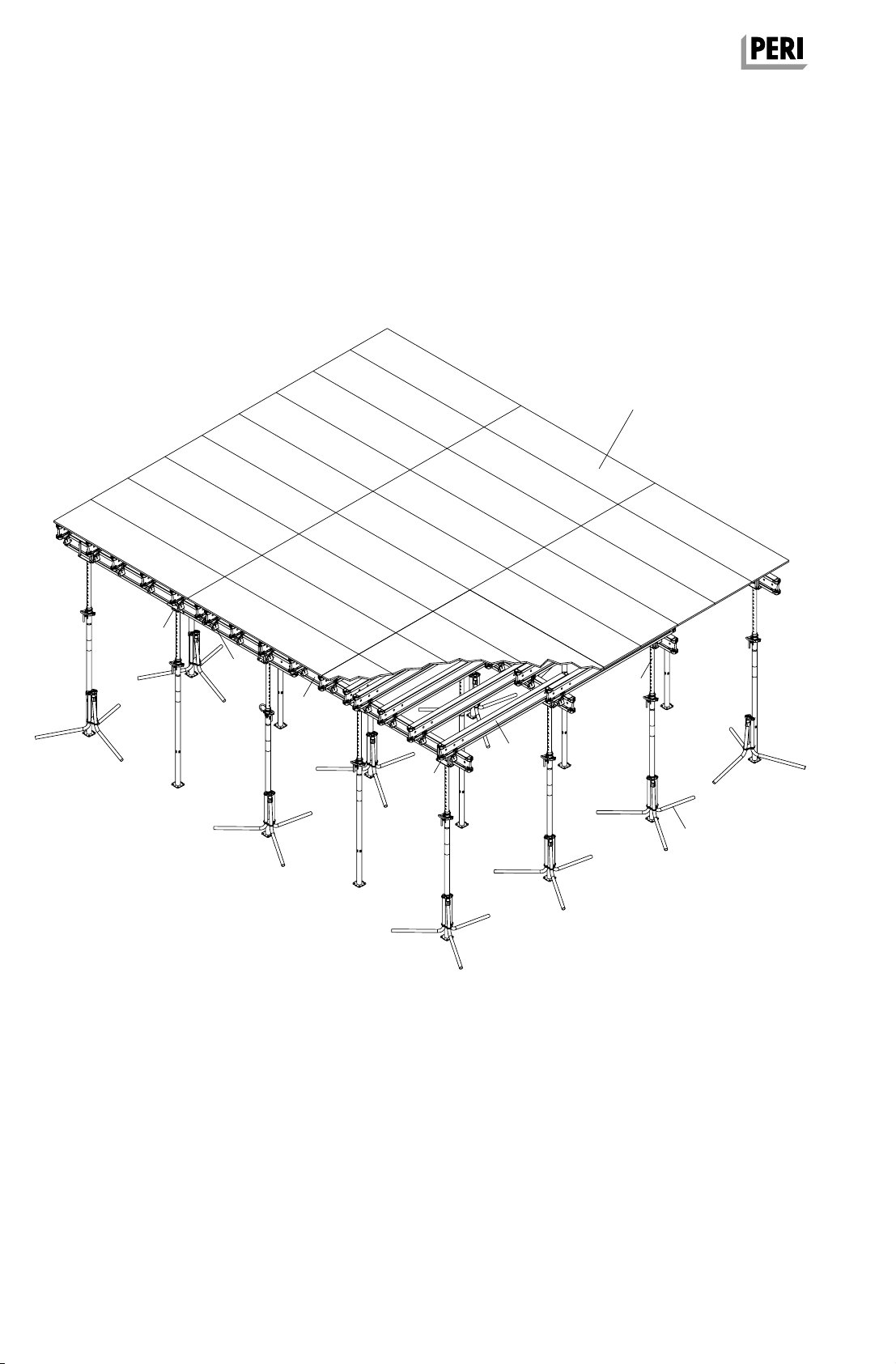
MULTIFLEX Girder Slab Formwork
Assembly Instructions for Standard Configuration
General
PERI products have been designed for
exclusive use in the industrial and com-
mercial sectors only by suitably trained
personnel.
These assembly instructions serve as
basis for the project-related risk assess-
ment and the instructions for the
provision and use of the system by the
contractor (user). However, they are
not intended to replace them.
Materials and working areas are to be
inspected on a regular basis especially
before each use and assembly, and
checked for signs of damage as well
as stability and functionality. Damaged
components must be exchanged
immediately on site and may no longer
be used.
Safety instructions and permissible
loads must be observed at all times.
Remove safety components only when
they are no longer required or if the
official representative of the contractor
gives instructions for this to take place.
For the application, inspection and repair
of our products, all current safety regula-
tions and guidelines must be observed
in the respective countries where they
are being used.
Storage and Transportation
Do not drop the components.
Store and transport components ensur-
ing that no unintentional change in their
position is possible. Detach lifting gears
from the lowered units only if they are in
a stable position and no unintentional
change is possible.
During the moving procedure, ensure
that components are picked up and set
down so that unintentional falling over,
falling apart, sliding or rolling is avoided.
Use only suitable load-carrying equip-
ment to move the components as well
as the designated load-bearing points.
During the moving procedure, always
use a guide rope.
Move components on clean, flat and
sufficiently load-bearing surfaces only.
Use original PERI storage and transport
systems, e.g. crate pallets, pallets or
stacking devices.
Safety Instructions
Components provided by the contractor
must conform with the characteristics
required in these assembly instructions
as well as with all valid construction
guidelines and standards. In particular,
the following applies if nothing else is
specified:
– timber components: Strength Class
C24 for Solid Wood according to
EN 338.
– scaffold tubes: galvanised steel
tubing with minimum dimensions
Ø 48.3 x 3.2 mm according to
EN 12811-1:2003 4.2.1.2.
– scaffold tube couplings according
to EN 74.
Deviations from the standard configura-
tion may only be carried out after a
separate risk assessment has been
completed by the contractor (user).
On this basis, appropriate measures for
the working safety and stability are to
be implemented.
The contractor must ensure that the
assembly instructions provided by PERI
are available at all times for the users
and must ensure they are also fully
understood.
During unfavourable weather conditions,
suitable precautions and measures are
to be implemented in order to guarantee
working safety and stability.
After exceptional events or long periods
of downtime whereby the formwork or
sub-structure was not used, the unit and
its components must be checked for
signs of damage as well as stability and
functionality.
The contractor (user) must ensure the
stability throughout all phases of con-
struction. He must ensure and verify
that all loads which occur are safely
transferred.
The contractor (user) has to provide safe
working areas for site personnel which
are to be reached through the provision
of safe access ways. Areas of risk must
be cordoned off and clearly marked.
Hatches and openings on accessible
working areas must be kept closed
during working operations.
The contractor must ensure that the
user fulfils the minimum requirements
for personal protective equipment, e.g.:
– Safety gloves,
– Safety helmet,
– Safety shoes,
– Safety goggles,
– PSAgA.
Residual Risks
The materials and components fully
complied with all valid safety regulations
at the time when they were first availa-
ble on the market. Nevertheless, a resid-
ual risk cannot be excluded even when
used as intended.
Possible residual risks and the resulting
dangers are described in the respective
chapter.