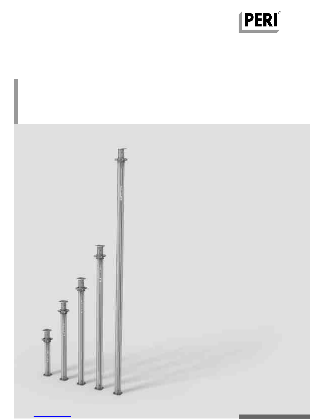
3Instructions for Assembly and Use – Standard Configuration
MULTIPROP Slab Props
Introduction
Safety instructions
Brochure:
– MULTIPROP Aluminium Slab Props
Type tests for:
– MULTIPROP Props
– MULTIPROP System
– MULTIPROP Props with Base MP 50
– MULTIPROP System with Base MP 50
General
1. Deviations from the standard configu-
ration and/or intended use present a
potential safety risk.
2. All country-specific laws, standards
and other safety regulations are to be
taken into account whenever our prod-
ucts are used.
3. During unfavourable weather condi-
tions, suitable precautions and meas-
ures are to be taken in order to ensure
both working safety and stability.
4. The contractor (user) must ensure
the stability throughout all phases of
construction. He must ensure and veri-
fy that all occuring loads are safely
transferred.
5. The contractor (user) has to provide
safe working areas for site personnel
which can be reached through the pro-
vision of safe access means. Areas of
risk must be cordoned off and marked.
Hatches and openings on accessible
working areas must be kept closed dur-
ing working operations.
6. For better comprehensibility, detailed
drawings are partly incomplete. The
safety installations which have possibly
not been included in these detailed
drawings must nevertheless still be
available.
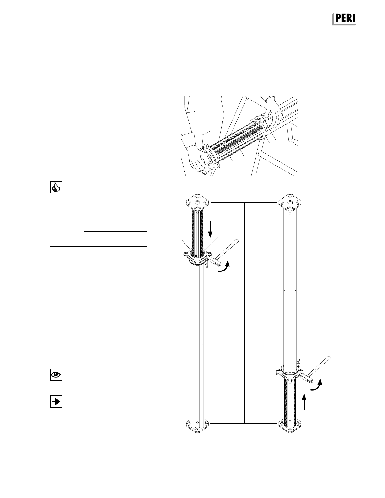
System-specific
1. Retract components only when the
concrete has sufficiently hardened and
the person in charge has given the
approval for striking to take place.
2. Anchoring is to take place only if the
anchorage has sufficient concrete
strength.
3. After exceptional occurrences or long
periods of downtime at the location
where the formwork or shoring is used,
the unit and its components must be
checked for stability and functionality.
Care and maintenance
1. MULTIPROP Slab Props have been
designed for long-term use on the con-
struction site.
2. In order to maintain the value and
operational readiness of the MULTIPROP
Slab Props over a long period of time,
the props should be carefully handled at
all times.
3. Occasionally grease the rubbing plate
to ensure easier handling.
4. Only PERI qualified personnel are
allowed to carry out repairs on the
MULTIPROP Slab Props.
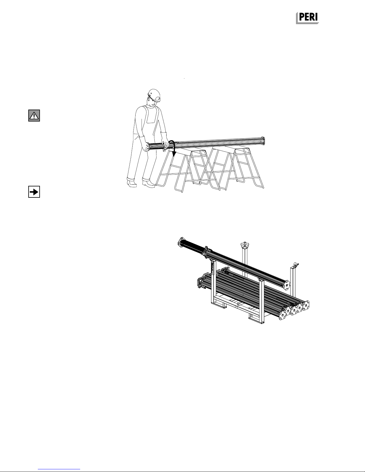
Storage and transportation
1. Do not drop the components.
2. Store and transport components
ensuring that no unintentional change
in their position is possible. Detach lift-
ing gear from the lowered units only if
these are in a stable position and no
unintentional change is possible.
3. When moving the components,
make sure they are lifted and set down
in a way that any unintentional tilting
over, falling apart, sliding or rolling away
is prevented.
4. Use only suitable load-carrying
equipment to move the components as
well as the designated load-bearing
points.
5. During the lifting and moving proce-
dure, ensure that all loose parts are
removed or secured.
6. Assemble and move components on
clean, flat and sufficiently load-bearing
surfaces only.
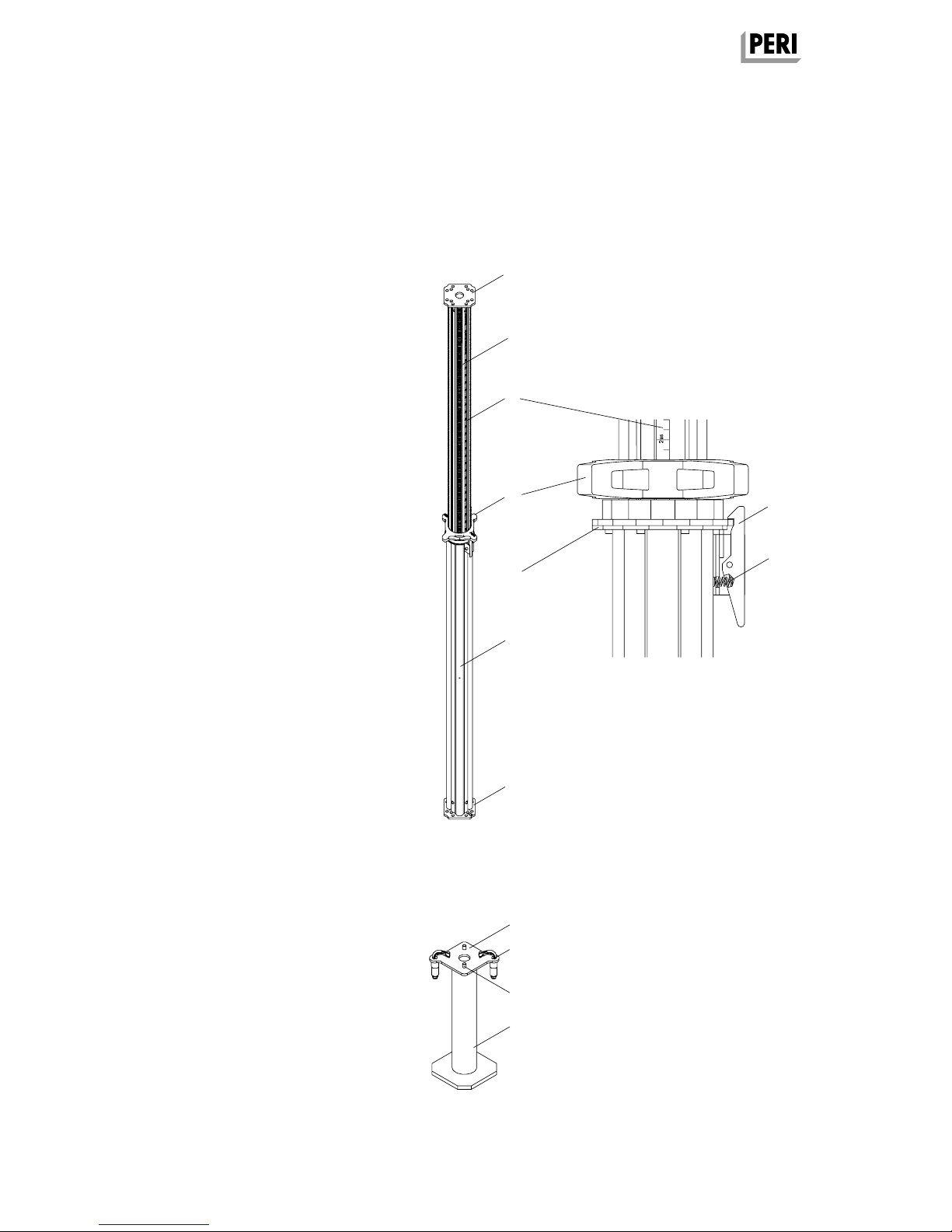
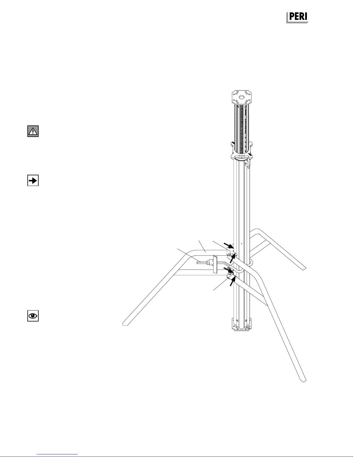
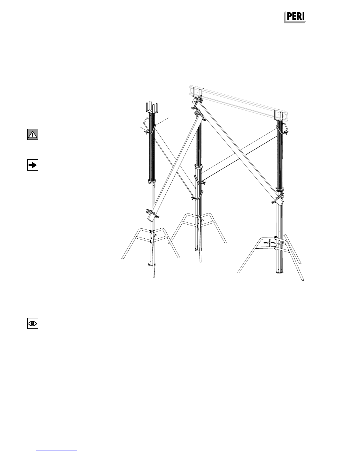
General
The structures shown in these Instruc-
tions for Assembly and Use are exam-
ples and feature only one component
size.They are valid accordingly for all
component sizes contained in the
standard configuration.
Instructions for Use:
– Pallets and Stacking Devices
Instructions for Assembly and Use:
– MULTIFLEX
– SKYDECK
– TABLE MODULES / SLAB TABLES
– SKYTABLE
– VARIODECK
Additional PERI product information
PERI design tables
EX_AuV_MULTIPROP_MP_Deckenstutzen.indb 3 24.03.16 15:10