Perlick HP15 User manual

Luxury
Operation &
Installation Manual
Signature Series (HP15-, HP24- and HP48-inch models)
Form No. Z2259
Rev. 06/07/2012
HP15TS
HP24TS
HP48RT
Beer Dispenser Models Only


3
Operation & Installation Manual
Signature Series Beer Dispensers (HP15, HP24 and HP48 models)
INTRODUCTION
Congratulations on your purchase of a Perlick residential
refrigeration product. Perlick has taken its expertise and experience
into creating the highest quality and most innovative residential
products on the market. Perlick’s product oering gives you the
opportunity to enjoy the functionality and user friendliness in
just about any room of your home, including kitchens, bedrooms,
entertainment rooms, basements and even bathrooms. All Perlick
products are built with commercial-grade stainless steel – providing
you with the beauty and durability for a lifetime of use.
This Installation and Operation Manual will answer your questions
about the features, operation and maintenance of your Refrigerated
Cabinet model. If you have questions that are not addressed here,
call 800 558-5592.
IMPORTANT : PLEASE READ all instructions completely before
attempting to install or operate the unit. First, as you follow these
Installation and Operation instructions, take particular note of the
DANGER!, CAUTION! and WARNING! symbols when they appear.
This information is important for the safe and ecient installation,
operation and care of your Perlick unit.
DANGER
Indicates a hazard that will result in serious injury or death if
precautions are not followed.
WARNING
Indicates a hazard may cause serious injury or death if
precautions are not followed.
CAUTION
Indicates a hazard where minor injury or product damage may
occur if you do not follow instructions.
Once the unit is completely installed, we suggest you keep this
manual and purchasing documentation in a safe place for future
reference. Should problems occur: refer to the troubleshooting
section of this manual. The information will help you quickly identify
a problem and get it remedied. In the event you require assistance,
please contact the dealer where you purchased your unit.
WARRANTY REGISTRATION CARD
To request information or service, the model number and serial
number must be provided. This information is located on the inside
ceiling of the unit and on the warranty registration card included
with information packet shipped with the unit.
IMPORTANT : Read through the included warranty statement
then complete and mail the Warranty Registration Card as
soon as possible to validate the registration date. Warranty
registration can also be done online at www.perlick.com. If
warranty registration is not completed, Perlick will use the date
of sale as the rst date of warranty for the unit. Please record the
purchase date of the unit and the dealer’s name, address and
telephone number below.
MODEL NUMBER: ____________________________________
SERIAL NUMBER: ____________________________________
PURCHASE DATE: ___________________________________
DEALER NAME & ADDRESS:
__________________________________________________
__________________________________________________
__________________________________________________
DEALER PHONE: ____________________________________
Table of Contents
Introduction ..........................................................................................................3
Warranty Registration ..................................................................................... 3
General Precautions .........................................................................................4
Installation Specications .............................................................................4
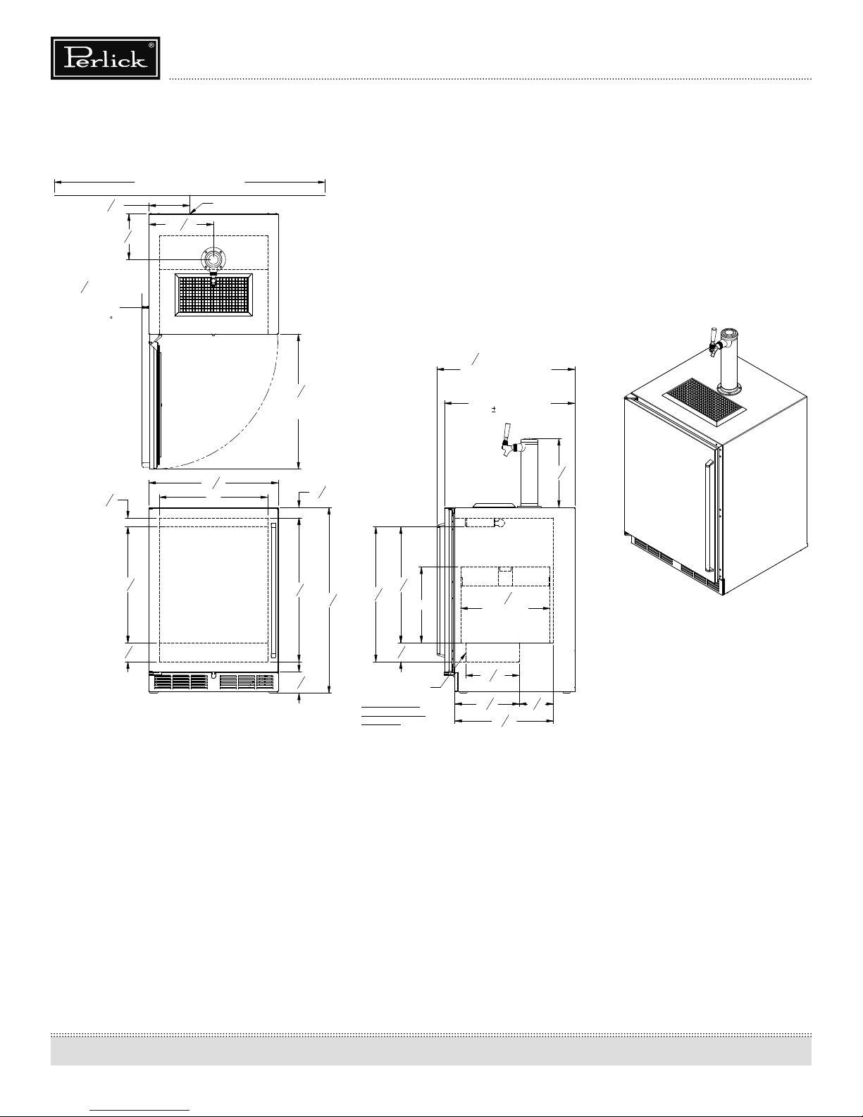
Overall Dimensions and Drawings ......................................................... 5
Preparing the Space ........................................................................................8
Preparing the Electrical Connections ...................................................8
Unpacking and Moving .................................................................................8
Anti-tip Brackets ................................................................................................. 9
Installation .............................................................................................................10
Shelving ................................................................................................................... 11
Toe Plate Wood Overlay Drawings..........................................................12
Shelf and Drawer Removal ..........................................................................14
Door Options and Wood Overlay Installation ..................................15
Operation ............................................................................................................... 24
General .................................................................................................................24
Temperature Controller ..............................................................................25
Unit Temperatures/Product Temperature ......................................26
Cleaning and Maintenance ......................................................................... 26
Installing Tapping Equipment ...................................................................27
Mounting Hole Template for Draft Arms ............................................30
CO2 Connections .............................................................................................. 31
Tapping a Keg ......................................................................................................32
Cleaning the Beer System ............................................................................33
Pouring the Perfect Glass of Beer ............................................................34
Troubleshooting .................................................................................................35
Warranty ..................................................................................................................37

4
Operation & Installation Manual
Signature Series Beer Dispensers (HP15, HP24 and HP48 models)
GENERAL PRECAUTIONS
DANGER
Risk of child entrapment, before you throw away your old
refrigerator or freezer, take o the doors and leave shelves in
place so that children may not easily climb inside.
DANGER
Altering, cutting of the power cord, or removal of the power
cord, removal of power plug, or direct wiring can cause serious
injury, re and/or loss of property and/or life and will void the
warranty.
WARNING
• Never attempt to repair or perform maintenance on the unit
until the electricity has been disconnected.
• The anti-tip kit must be installed on this unit before it is used.
Never use the drawers, shelves or door as steps or to support
more than they were designed to support.
CAUTION
• Do not lift unit by drawer or door handles.
• Failure to clean the condenser every three (3) months can
cause the unit to malfunction. This could void the warranty.
• Never install the unit behind closed doors. Be sure front
louvered toe plate is free of obstruction. Obstructing the
airow can cause unit to malfunction, and may void the
warranty.
CAUTION
Use only genuine Perlick replacement parts. Imitation parts can
damage the unit, and may void the warranty.
INSTALLATION INSTRUCTIONS
GENERAL
• All electrical instructions assume that outlet is located 4 to 10
inches from oor.
• Floor must be level in area of installation. Leg levelers are used
for ne-tune adjustment only and should not be used to com-
pensate for oor dierences exceeding 1/2-inch.
• When moving unit into position, take care to protect oor sur-
face with cardboard, rugs, etc.
• Never attempt to move unit without the aid of at least one
other person.
• Always secure door shut prior to moving the unit.
FINISHED OPENING REQUIREMENTS
24” Signature Series
Height Depth Width
34-3/8” minimum,
35-1/2” maximum
24” 24”
48” Signature Series
Height Depth Width
34-3/8” minimum,
35-1/2” maximum
24” 48”
15” Signature Series
Height Depth Width
34-3/8” minimum,
35-1/2” maximum
24” 15”

5
Operation & Installation Manual
Signature Series Beer Dispensers (HP15, HP24 and HP48 models)
HP15TS Model
(Figure 1)
"
Min. clearance
for door swing.
15
15
16
50" Area in which
electrical outlet must be located
5
1
16
"
12
3
4
"
11
7
8
" 6
1
4
"
3
1
2
"
23
1
16
"
9
sixth
barrel.
"
4
3
18
3
16
"
"
2
1
23 Typical
7
8
" 24
3
1
2
"
21
3
8
"
1
5
8
" 1
15
16
"
26
9
16
"
11"
Power cord 65/8" off floor.*
16
"7
7
8
7
16
"
(with
24"
1/16" toleramce)
25
7
16
" Values may change
due to custom pull
with a wood overlay door.
SCALE: 1:10
DATE:
MILWAUKEE, WI 53223
PERLICK CORPORATION
NOT TO BE COPIED OR USED DETRIMENTAL TO OUR INTERESTS
DR.:
PRINTED
J:\Dwg\95000\95004.slddrw
4/12/2012
95004
9/30/09
DAS
PROPERTY OF THE PERLICK CORP.
SHEET 2 OF 3
Signature Series HP15 Models
Tapping
* Leg leveler can add
3/4" to these dimensions
when fully extended.
14
7
"
8
"*34
1
4
*3 7/8"
4/12/2012 1:32 PM

6
Operation & Installation Manual
Signature Series Beer Dispensers (HP15, HP24 and HP48 models)
HP24TS Model
(Figure 2)
20"
1
5
8
"
21
3
8
"
3
1
2
"
26
9
16
"
1
15
16
"
50" Area in which
electrical outlet must be located
7
9
16
"
1
1
4
" Min.
clearance from
a corner to
acheive 90
door swing.
24
15
16
"
Min. clearance
for door swing.
12
3
4
"
16
1
2
"
Typical
quarter barrel.
14"
3
1
2
"
21
3
8
"
9
15
16
"
11
7
8
" 6
1
4
"
18
3
16
"
24
7
8
"
Tapping
Leg levelers can add
*
Signature Series HP24 Models
when fully extended.
3/4" to these dimensions
Also fits two sixth
barrels when shelf
is removed.
J:\Dwg\95000\95005.slddrw
SCALE: 1:10
MILWAUKEE, WI 53223
PERLICK CORPORATION
NOT TO BE COPIED OR USED DETRIMENTAL TO OUR INTERESTS
DR.:
PRINTED
DATE:
4/12/2012
95005
9/30/09
DAS
PROPERTY OF THE PERLICK CORP.
SHEET 2 OF 3
34
1
4
*
"
8
"
7
23
*3
7
8
"
Power cord 65/8" off floor. *
16
7
"8
11
15
16
"
Shelf included with
dispensing cabinets.
1/16" tolerance)
24"
(with
25
7
16
" Value may change
due to custom pull
with a wood overlay door.
4/12/2012 1:39 PM

7
Operation & Installation Manual
Signature Series Beer Dispensers (HP15, HP24 and HP48 models)
HP48RT Models
door swing.
1 1/4" Min.
clearance from
a corner to
acheive 90
12 1/4"
50" Area in which
electrical outlet must be located.
12 3/4"
3 3/16"
5 6/16" Max.
product ht.
6 3/4" 10 1/2"
17 1/4" product ht.
9 3/16"" Max.
product ht.
10 13/16" Max.
8 3/8"
6 3/16"
24 7/8"
26 9/16"
20 11/16"
12 3/4"
26 9/16" 19 7/8"
* Leg leveler can add
3/4" to these dimensions
when fully extended.
J:\Dwg\95000\95006.slddrw
SCALE: 1:12
MILWAUKEE, WI 53223
PERLICK CORPORATION
NOT TO BE COPIED OR USED DETRIMENTAL TO OUR INTERESTS
DR.:
PRINTED
DATE:
5/29/2012
95006
5/29/2012JMP
PROPERTY OF THE PERLICK CORP.
SHEET 4 OF 4
Power cord 81/4" off floor.*
11 15/16" 8 7/16"
17 11/16" 90°
for door swing.
Min. clearance
24 15/16"
1 3/8"
17 13/16"
Inside Drawer
(Top & Bottom)
(with 1/16" tolerance)
24"
25 7/16" Values may change
due to custom pull
with a wood overlay door.
(with 1/16" tolerance)
24"
25 7/16" Values may change
due to custom pull
with a wood overlay door.
Signature Series HP48 Models
*34 5/16"
*4"
47 7/8"
5 1/4"
19 5/8" 26 9/16"
19 7/8"
19 7/8" 24 7/8"
26 9/16"
20 11/16"
12 3/4"
26 9/16"
6 3/8" 11 3/4"
18 1/8"
19 5/8"
5 1/4"
12 3/4"
1 1/4" Min.
clearance from
a corner to
acheive 90
door swing.
24 15/16"
Min. clearance
for door swing.
12 1/4"
50" Area in which
electrical outlet must be located.
* Leg leveler can add
3/4" to these dimensions
when fully extended.
J:\Dwg\95000\95006.slddrw
SCALE: 1:12
MILWAUKEE, WI 53223
PERLICK CORPORATION
NOT TO BE COPIED OR USED DETRIMENTAL TO OUR INTERESTS
DR.:
PRINTED
DATE:
5/29/2012
95006
4/24/2012JMP
PROPERTY OF THE PERLICK CORP.
SHEET 3 OF 4
Signature Series HP48 Models
*34 5/16"
*4"
47 7/8"
(with 1/16" tolerance)
24"
25 7/16" Values may change
due to custom pull
with a wood overlay door.
Shelf included with
dispensing cabinets.
(with 1/16" tolerance)
24"
25 7/16" Values may change
due to custom pull
with a wood overlay door.
Power cord 81/4" off floor.*
required for
clearance.
11 15/16"
pullout shelf
90° Swing
8 7/16"
Door (Figure 3)/Drawer
Models (Figure 4)

8
Operation & Installation Manual
Signature Series Beer Dispensers (HP15, HP24 and HP48 models)
PREPARING THE SPACE
Make sure that the space that the opening where the Perlick
cabinet(s) is/are to be installed is properly prepared. Refer to Figure
1 (page 5), Figure 2 (page 6) and Figure 3 (page 7) to ensure proper
space dimensions and electrical service are correct for the model
to be installed.
CAUTION
If cabinet is being installed under a countertop it is recommended
that the countertop be supported by structure other than the
refrigerated cabinet to prevent damage to the counter top.
IMPORTANT NOTE: For a cabinet door to operate properly, the
door must open a minimum of 90°. Use a minimum 3-inch ller in
corner installations to assure a 90° door opening. For HP15 models,
allow 16” clearance in front of the unit. For HP24 and HP48 units,
allow 24” clearance in front of the unit for full door swing, shelf pull-
out or drawer pull-out.
IMPORTANT NOTE: Make sure the oor under the unit is level
with the surrounding nished oor. Protect a nished oor with
plywood, cardboard or some other suitable material before moving
the unit into place. Failure to do this may result in damage to the
oor.
PREPARING ELECTRICAL CONNECTIONS
A 115 volt, 60Hz, 15 amp circuit breaker and electrical supply are
required. A separate circuit is required for each Perlick unit installed.
Follow the National Electrical Code and local codes and ordinances
when installing the receptacle.
All Perlick units come equipped with a NEMA 5-15P 90° plug with
a minimum of 5-feet of cord extending beyond the rear of the
cabinet. The electrical outlet must be ush with or recessed into
the back wall.
IMPORTANT NOTE: Never use an extension cord to extend the
power cord to the electrical receptacle.
DANGER
ELECTROCUTION HAZARD
Electrical grounding is required. This appliance is equipped with
a three prong (grounding) polarized plug for your protection
against possible shock hazards.
• Never remove the round grounding prong from the plug.
• Never use a two-prong grounding adapter.
• Never use extension cords to connect power to the unit.
Where a two-prong wall receptacle is encountered or a longer
power cord is required, contact a qualied electrician to have it
replaced in accordance with applicable electrical cords.
DANGER
Failure to comply with the above electrical guidelines may result
in possible injury, death, re or loss of property.
UNPACKING AND MOVING
CAUTION
Do not cut cardboard sleeve covering the unit. Cutting may
result in damage to the exterior of the cabinet.
1. Uncrate the unit outside on a at surface. Remove the card-
board sleeve by removing the banding holding the sleeve
to the shipping base. Carefully lift the cardboard sleeve up
over the top of the unit.
2. Carefully lift unit o base and onto a hand truck or dolly (this
should be done with a minimum of two people; larger units
may require additional helpers!). Make sure the unit is bal-
anced on transporting device using soft, exible strapping.
Protect unit surfaces with cloth material where strapping
contacts unit.
3. Before moving unit, secure door to unit with tape to the
door closed.
4. Carefully move unit to installation site and place in front of
opening.
WARNING
A minimum of two people should lift the cabinet o the base to
prevent possible personal injury.

9
Operation & Installation Manual
Signature Series Beer Dispensers (HP15, HP24 and HP48 models)
ANTI-TIP BRACKETS
WARNING
Unit may tip forward if loaded racks/shelves are all pulled
out at the same time. To prevent tipping and provide a stable
installation, the unit must be secured in place with the anti-tip
brackets provided with the unit.
A set of metal anti-tip brackets and necessary hardware is supplied
with the unit. The anti-tip brackets, when properly installed, should
secure the rear legs and prevent the unit from tipping forward.
Some installation sites may require modication to provide a secure
surface for attaching brackets. Refer to Figures 5 and 6 (right) and
Figure 7 (below) for mounting bracket locations for 15”, 24” and 48”
Signature Series models.
IMPORTANT NOTE: If installing on a concrete oor, concrete
fasteners are required and are not included in the Anti-Tip Kit.
Figure 7 - 48” Anti-Tip Kit Drawing
Figure 6 - 24” Anti-Tip Kit Drawing
15
16
"
13 1
32
"
3
16
"
FRONT OF UNIT
3
8
"
ANTI-TIP BRACKET
PART #63740
Figure 5 - 24” Anti-Tip Kit Drawing

10
Operation & Installation Manual
Signature Series Beer Dispensers (HP15, HP24 and HP48 models)
INSTALLATION
CAUTION
Finished ooring should be protected with the appropriate
material to avoid damage from moving the unit.
If unit has been laid on its back or sides, place unit upright and
allow minimum of 24 hours before connecting power.
1. Plug in the unit into the 15 amp grounded outlet located
in the installation opening. With power applied to the unit,
check that the lighting and cooling function operate proper-
ly, then turn o power to the wall outlet at the circuit breaker.
WARNING
Shut o power to the wall outlet before installing unit into the
opening.
2. Check that the following are level and square:
• front face and interior opening
• installation opening and oor surface
• countertop bottom front edge
IMPORTANT NOTE: The oor under the unit must be at the same
level as the surrounding nished oor.
3. If all surfaces are level, refer to Figure 8 (right) and perform
the following:
a. Measure from the oor to the bottom of the front edge of
the countertop.
b. Mesure the rear of the unit cabinet from oor to top of
cabinet, at back corners.
c. Adjust rear legs so B measurement equals A measurement.
Usingt an adjustable wrench of pliers, turn legs counter-
clockwise to raise the unit or clockwise to lower the unit.
IMPORTANT NOTE: Leveling legs should not extend more than
3/4” from bottom of the unit.
4. Slide cabinet into position. Make sure the rear levelling legs
slide under the anti-tip brackets. Push the unit into the open-
ing until the bottom front edge of the unit is ush with the
surrounding cabinetry, or until the rear legs are tight against
the anti-tip brackets.
5. Shim the front of the unit so the front face is ush with the
surrounding cabinetry. Adjust the front legs to support the
countertop at the shimmed height. Using an adjustable
wrench or pliers, turn the legs counterclockwise to raise the
unit or clockwise to lower the unit. Countertop should be
resting on top of the unit.
IMPORTANT NOTE: If countertop is not resting entirely on unit top,
shim the countertop to prevent damage to the countertop.
CAUTION
To prevent damage to the countertop and unit underneath, do
not place heavy objects on countertop directly above the unit.
6. Check interior door openings inside the cabinet to ensure
the cabinet is level. Reinstall all shelving and sliding drawers
squarely into slide brackets and proper slide bracket grooves.
When sliding shelving and drawers are installed properly
a click should be heard from both slide bracket retaining
clips and should slide smoothly in the tracks. When sliding
shelving or drawers are pulled out to full extension a stop is
activated to prevent additional pull-out.
CAUTION
Improper shelving or drawer installation may not actuate slide
top mechanism.
Figure 8 - Leveling

11
Operation & Installation Manual
Signature Series Beer Dispensers (HP15, HP24 and HP48 models)
TOE PLATE INSTALLATION
When the unit is secured in place, install the louvered toe plate.
Secure louvered toe plate by snapping the latch into the latch
catch on the unit. Refer to Figure 9 (below) for Toe Plate Installation
Illustration and Figures 10 (page 12) and 11 (page 13) for Toe Plate
Wood Overlay template.
CAUTION
The louvered toe plate must be removed to service the unit. The
oor cannot interfere with removal. The louvered sections must
not be covered or obstructed to prevent proper air circulation.
IMPORTANT NOTE: To achieve maximum performance, interior
louver openings and fan guard openings should never be
obstructed.
SHELVING
HP15TS Single Door Beer Dispenser
Shelving not available
HP24TS Single Door Beer Dispenser
Shelving not available
HP48RT Two Door Refrigerator/Beer Dispenser
The two door refrigerator/beer dispenser (HP48RT) comes standard
with two full-extension black vinyl-coated pullout shelves on the
refrigerator side. Shelving not available on beer dispenser side.
HP48RT Drawer/Door Refrigerator/Beer Dispenser
Shelving not available
Figure 9- Toe Plate Installation

12
Operation & Installation Manual
Signature Series Beer Dispensers (HP15, HP24 and HP48 models)
Figure 10- Toe Plate Wood Overlay Template for HP15TS
7 1/16"
3/4"
1"
4 1/8"
C
FRONT VIEW
11/16"
17/64"
R
1/4"
1 29/32"
B
B
D
REAR VIEW
NOTE: ALL INTERNAL RADII ARE 1/8IN UNLESS OTHERWISE SPECIFIED
1/32"
9/32"
SECTION B-B
SCALE 1 : 2
1"
5/16"
TYPICAL
1/4"
TYPICAL
3"
TYPICAL
3/16"
TYPICAL
29/32"
DETAIL C
SCALE 1 : 2
3/8"
3/8"
11/16"
1"
3/32"
5/32"
43/64"
29/64"
7/64"
DETAIL D
SCALE 1 : 1
3/8"
1/2"
7/8"
1/8"
3/32"
9/32"
9/32"
7/64" 7/64"
1/4"
METAL CLIP REQUIRED FOR SNAP IN RETAINER THAT
ASSEMBLES GRILL TO THE UNIT. THIS CLIP MUST BE
SCREWED TO THE GRILL USING THE FEATURES SHOWN
IN DETAIL VIEW "D"
1/32"
THICK (20GA)
GALVANIZED OR
STAINLESS STEEL
RECOMMENDED
2
2
B
A
3
C
B
A
1
C
1
3
SW
THIS DOCUMENT / PUBLICATION / SOFTWARE / DRAWING CONTAINS PROPRIETARY INFORMATION WHICH IS THE PROPERTY OF THE PERLICK CORPORATION. IT MAY NOT BE REPRODUCED OR TRANSMITTED IN ANY FORM, ELECTRONIC OR MECHANICAL,
INCLUDING PHOTOCOPYING, RECORDING, OR USED IN ANYINFORMATION STORAGE, TRANSMISSION, OR RETRIEVAL SYSTEM, WITHOUT WRITTEN PERMISSION FROM THE PERLICK CORPORATION. COPYRIGHT 2001 PERLICK CORPORATION. ALL RIGHTS RESERVED.
SHEET 3 OF 4
SCALE =
TITLE:
Perlick Corporation
MATERIAL:
DATE
SIGNATURES
DESIGNED
DRAWN
CHECKED
Milwaukee, Wisconsin
PURCHASE REC.:
REFERENCE:
UNLESS OTHERWISE SPECIFIED:
PART NO.
DWG NO.
REVISIONS
GRILL, WOOD
15IN
WOOD GRILL
WOOD GRILL, 15IN
NAH
4/23/2008
NAH
4/23/2008
4/23/2008
1:3
WOOD
QTY.:
FINISH:
4/23/2008
BREAK SHARP EDGES - 015 X 45°.
RADIUS SHARP FILLETS - .015 TO .031
DIMENSIONS ARE IN INCHES
TOLERANCES:
.X= ,
.XX = ,
.XXX = ,
ANGULAR: ±1.0°, FRACTIONS: ±1/16
J:\Dwg\_ Assembly\HHC GEN2\HHC GEN2 24IN RESIDENTIAL\Wood Grill.slddrw

13
Operation & Installation Manual
Signature Series Beer Dispensers (HP15, HP24 and HP48 models)
11 9/16"
3/4"
R
1/4"
1"
23 7/8"
3 27/64"
1"
C
FRONT VIEW
11/16"
17/64"
1 13/64" 1 13/64"
B
B
D
REAR VIEW
NOTE: ALL INTERNAL RADII ARE 1/8IN UNLESS OTHERWISE SPECIFIED
1/32"
9/32"
SECTION B-B
SCALE 1 : 2
1"
5/16"
TYPICAL
3/8"
TYPICAL
3"
TYPICAL
3/16"
TYPICAL
7/32"
DETAIL C
SCALE 1 : 2
3/8"
3/8"
11/16"
1"
3/32"
5/32"
43/64"
29/64"
DETAIL D
SCALE 1 : 1
3/8"
1/2"
7/8"
1/8"
3/32"
9/32"
9/32"
7/64" 7/64"
1/4"
METAL CLIP REQUIRED FOR SNAP IN RETAINER THAT
ASSEMBLES GRILL TO THE UNIT. THIS CLIP MUST BE
SCREWED TO THE GRILL USING THE FEATURES SHOWN
IN DETAIL VIEW "D"
1/32"
THICK (20GA)
GALVANIZED OR
STAINLESS STEEL
RECOMMENDED
NOTE: GRILL SHOWN ON THIS PAGE IS FOR EITHER A SINGLE STAND ALONE UNIT OR
THE BOTTOM UNIT OF A STACKED CONFIGURATION
2
2
B
A
3
C
B
A
1
C
1
3
SW
THIS DOCUMENT / PUBLICATION / SOFTWARE / DRAWING CONTAINS PROPRIETARY INFORMATION WHICH IS THE PROPERTY OF THE PERLICK CORPORATION. IT MAY NOT BE REPRODUCED OR TRANSMITTED IN ANY FORM, ELECTRONIC OR MECHANICAL,
INCLUDING PHOTOCOPYING, RECORDING, OR USED IN ANYINFORMATION STORAGE, TRANSMISSION, OR RETRIEVAL SYSTEM, WITHOUT WRITTEN PERMISSION FROM THE PERLICK CORPORATION. COPYRIGHT 2001 PERLICK CORPORATION. ALL RIGHTS RESERVED.
SHEET 1 OF 4
SCALE =
TITLE:
Perlick Corporation
MATERIAL:
DATE
SIGNATURES
DESIGNED
DRAWN
CHECKED
Milwaukee, Wisconsin
PURCHASE REC.:
REFERENCE:
UNLESS OTHERWISE SPECIFIED:
PART NO.
DWG NO.
REVISIONS
GRILL, WOOD
STAND ALONE
WOOD GRILL
WOOD GRILL, STACKING
NAH
4/23/2008
NAH
4/23/2008
4/23/2008
1:3
WOOD
QTY.:
FINISH:
4/23/2008
BREAK SHARP EDGES - 015 X 45°.
RADIUS SHARP FILLETS - .015 TO .031
DIMENSIONS ARE IN INCHES
TOLERANCES:
.X= ,
.XX = ,
.XXX = ,
ANGULAR: ±1.0°, FRACTIONS: ±1/16
J:\Dwg\_ Assembly\HHC GEN2\HHC GEN2 24IN RESIDENTIAL\Wood Grill.slddrw
Figure 11- Toe Plate Wood Overlay Template for HP24TS and HP48RT

14
Operation & Installation Manual
Signature Series Beer Dispensers (HP15, HP24 and HP48 models)
Adjusting Full-extension Shelving (HP48RT only)
1. Pull the shelf out to its farthest position. Locate the tabs in the
middle of both extenders (Figure 12). Lift one tab up while
pushing the opposite tab down and pull shelf out.
2. Reposition each bracket separately. Grasp the middle of
the bracket, pull the front end up and out, then forward to
remove (Figure 13).
3. Place bracket at the desired position. Push the rear hook into
the rear key slot. Set front of the bracket on the wall hook.
4. Repeat for other bracket(s).
5. Push extenders completely into the unit. Align the shelf
grooves with the extenders and slide completely into the
unit.
Drawers
Drawer units (available on HP48RT model only) come standard
with two drawers. Like shelving, drawers are full-extension.
To remove drawers:
1. Pull the drawer out to its farthest point.
2. Locate the tabs in the middle on both sides of the extenders.
Press left tab up and right tab down; pull shelf out.
3. Move each extender separately. Hold the middle of one ex-
tender, pull the front up then move extender 1/2-inch to the
inside of unit. Pull up, then out.
4. Place extender at desired height, place rear stando screw
into rear pilaster, slide back. Place front stand-o screw into
front pilaster, slide down.
5. To return drawer, rst push both extenders completely in
then line up the shelf grooves and slide easily into the unit.
CAUTION
Completely empty the drawer before removing.
Figure 12- Tab location
Figure 13 - Bracket and extender location
Lift one tab up while pushing the
opposite tab down and pull shelf out
To remove brackets,
remove shelf, lift front
of bracket to disengage
the front key slot, and
pull forward to disengage
the rear key slot.

15
Operation & Installation Manual
Signature Series Beer Dispensers (HP15, HP24 and HP48 models)
DOOR OPTIONS
Perlick residential units oer a variety of door panel design
alternatives; solid stainless steel, solid wood overlay, glass with
stainless steel trim and glass with wood overlay trim.
Solid stainless steel and stainless steel glass doors are shipped from
the factory with decorative stainless steel panels and handles in
place on the appliance.
Solid wood overlay and glass wood overlay doors are designed to
accept a decorative front panel to match surrounding cabinetry
and door handles. The panel and door handles are supplied by the
customer.
All Perlick units accept any of the above door congurations and
are fully interchangable.
IMPORTANT NOTE: Units with a beer dispenser only can utilize a
solid stainless steel door or solid wood overlay door.
IMPORTANT NOTE: Glass with stainless trim and glass with wood
trim may sweat in conditions with relative humidity over 75%.
WOOD OVERLAY INSTALLATION
Before beginning installation, check all components for proper t
and nish.
WARNING
• All overlay doors require a trim panel of at least 3/4” thick.
• The solid wood overlay panel should not weight more than
20 pounds.
• The glass wood overlay panel should not weight more than
10 pounds.
The following instructions cover installing a solid wood overlay or
glass wood overlay panel and handle to a door or drawer.
IMPORTANT NOTE: Contact the factory or visit www.
bringperlickhome.com for full size wood overlay panel layouts.
Once on the site, select ‘Service and Support’ from the top menu
bar and click on ‘Wood Overlay Templates’. Take care in chosing the
correct template for your specic model.
IMPORTANT NOTE: You must install optional lock and handle
PRIOR to mounting the wood overlay onto the door frame.
Panel drawings:
Refer to Figure 15 for 15” solid wood overlay panel (page 16).
Refer to Figure 17 for 24” solid wood overlay panel (page 18).
Refer to Figure 18 for 24” for glass wood overlay panel (page 19).
Refer to Figure 19 for 24” drawer wood overlay panel (page 20).
Door Lock Installation (optional)
When installing to wood overlay, perform lock installation before
mounting wood overlay to door.
1. See Figure 14 (below), attaching mounting bracket to wood
overlay.
2. Insert lock body and attach with nut.
Lock installation drawings:
Refer to Figure 16 for Lock Installation on 15” solid wood overlay
panel (page 17).
Refer to Figure 20 for Lock Installation on 24” solid wood overlay
panel (page 21).
Refer to Figure 21 for Lock Installation on 24” glass wood overlay
panel (page 22).
Refer to Figure 22 for Lock Installation on 24” drawer wood overlay
panel (page 23).
Mounting bracket
Screw
Lockwasher
Lock strike
Nut
Lock bracket
Lock body
Figure 14 - Lock installation

16
Operation & Installation Manual
Signature Series Beer Dispensers (HP15, HP24 and HP48 models)
Figure 15 - Solid wood overlay panel template for HP15TS

17
Operation & Installation Manual
Signature Series Beer Dispensers (HP15, HP24 and HP48 models)
Figure 16 - Lock installation, solid wood overlay door panel for HP15TS

18
Operation & Installation Manual
Signature Series Beer Dispensers (HP15, HP24 and HP48 models)
Figure 17 - Solid wood overlay panel template for HP24TS and HP48RT

19
Operation & Installation Manual
Signature Series Beer Dispensers (HP15, HP24 and HP48 models)
Figure 18 - Glass wood overlay panel template for HP24TS and HP48RT

20
Operation & Installation Manual
Signature Series Beer Dispensers (HP15, HP24 and HP48 models)
Figure 19 - Wood overlay drawer panel template for HP24TS and HP48RT
Other manuals for HP15
6
This manual suits for next models
5
Table of contents
Other Perlick Kitchen Appliance manuals

Perlick
Perlick DP32B User manual

Perlick
Perlick RS-CDK User manual

Perlick
Perlick Signature Series HP15TS User manual

Perlick
Perlick Shallow Depth HH24WS-1X Owner's manual

Perlick
Perlick 63134-1 User manual

Perlick
Perlick H Series User manual

Perlick
Perlick HC24BB User manual

Perlick
Perlick HP24ZO-4 User manual

Perlick
Perlick HH Series Owner's manual

Perlick
Perlick HP24TS/TO User manual