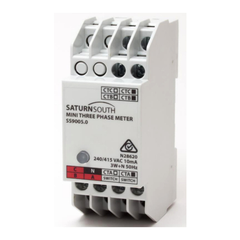
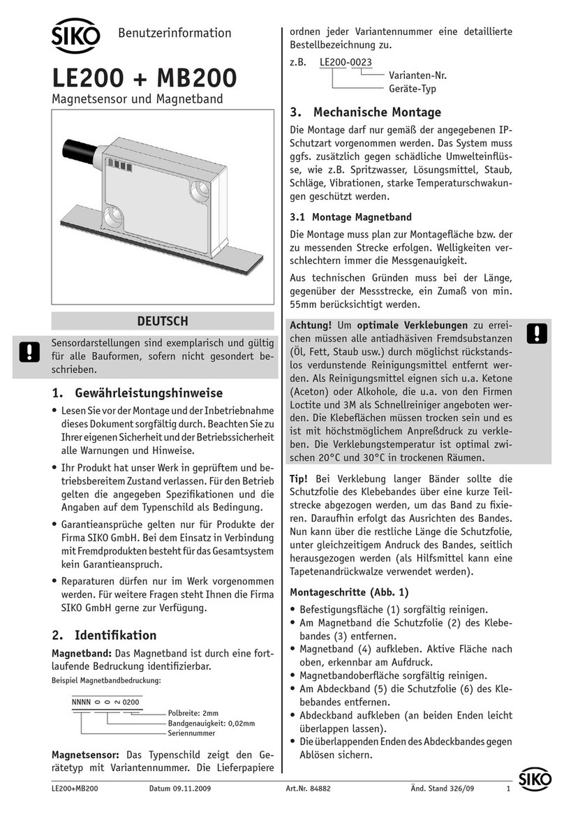
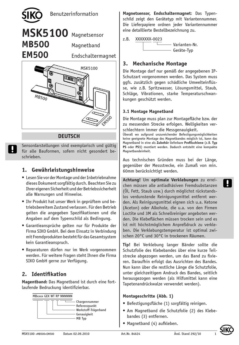
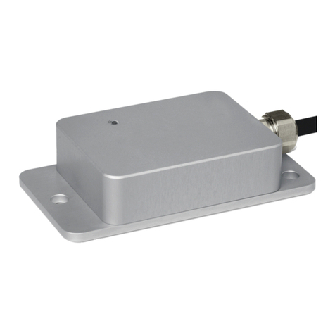
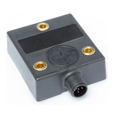
Siko IK360 Operation manual

IK360, IK360L Datum 10.02.2015 Art. Nr. 85814 Änd. Stand 52/15 1
Abb. 1: Anzahl Achsen 1
Ausgangspunkt Mitte Winkelstellung (Werkseinstellung)
Abb. 2: Anzahl Achsen 2
X = Y = 0°
Mitte Winkelstellung
(Werkseinstellung)
X - Achse Y - Achse
DEUTSCH
1. Dokumentation
Zu diesem Produkt gibt es folgende Dokumente:
• Produkt-Datenblatt
• Benutzerinformation (dieses Dokument)
• Benutzerhandbuch RS232 (beiliegende CD)
• Benutzerhandbuch CANopen (beiliegende CD)
Diese Dokumente sind auch unter "http://www.
siko-global.com/p/ik360" oder "http://www.siko-
global.com/p/ik360l" zu finden.
2. Gewährleistungshinweise
• LesenSievorderMontageundderInbetriebnahme
diesesDokumentsorgfältigdurch.BeachtenSiezu
IhrereigenenSicherheitundderBetriebssicherheit
alle Warnungen und Hinweise.
• Ihr Produkt hat unser Werk in geprüftem und be-
triebsbereitemZustandverlassen.FürdenBetrieb
gelten die angegebenen Spezifikationen und die
Angaben auf dem Typenschild als Bedingung.
• Garantieansprüche gelten nur für Produkte der
Firma SIKO GmbH. Bei dem Einsatz in Verbindung
mitFremdproduktenbestehtfürdasGesamtsystem
kein Garantieanspruch.
• Bei Störungen oder Geräteausfällen sollten Sie
niemals versuchen, die Geräte selbst zu önen.
Ansonsten setzen Sie sich der Gefahr aus, mit
Teilen, die unter hoher Spannung stehen, in
Kontakt zu geraten.
• Reparaturen dürfen nur im Werk vorgenommen
werden. Für weitere Fragen steht Ihnen die Firma
SIKO GmbH gerne zur Verfügung.
3. Identifikation
Das Typenschild zeigt den Gerätetyp mit Varianten-
nummer. Die Lieferpapiere ordnen jeder Varianten-
nummer eine detaillierte Bestellbezeichnung zu.
z. B. IK360-0023
Varianten-Nr.
Geräte-Typ
4. Kurzbeschreibung
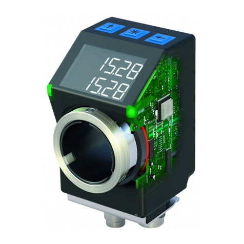
Der IK360, IK360L Inklinometer (Neigungssensor)
ist ein einfaches, hoch integriertes und kompaktes
Messgerät. Er misst den Winkel absolut zum Lot.
Der IK360, IK360L wird in verschiedenen Ausfüh-
rungen ausgeliefert:
• RS232 Schnittstelle + Analog Spannungsausgang
• RS232 Schnittstelle + Analog Stromausgang
• CANopen Schnittstelle
5. Mechanische Montage
Der IK360, IK360L ist ein vorkalibriertes Gerät, das
sofort in Betrieb genommen werden kann. Die Mon-
tagefläche muss plan und frei von Staub und Fett
sein. Verwenden Sie 3 Stück M4 Zylinderschrauben
zur Befestigung. Beachten Sie das gleichmäßige
Anzugsmoment von 1.5 … 2.5 Nm der Schrauben.
Die Seite mit den markierten Achsen und dem Ty-
penschild ist die Oberseite des Inklinometers.
Benutzerinformation
IK360, IK360L
Inklinometer

2 IK360, IK360L Datum 10.02.2015 Art. Nr. 85814 Änd. Stand 52/15
Ansichtsseite = Steckseite
Ansichtsseite
= Steckseite
6. Elektrischer Anschluss
Der Inklinometer wird über einen runden
8-poligen/5-poligen M12 Standardstecker (A-ko-
diert) angeschlossen. Besonders bei erforderlicher
Schutzart IP69K ist auf den geeigneten Steckver-
binder und das Anzugsmoment von 0.4 … 0.6 Nm
zu achten.
Das Anschlusskabel ist mit einer Kabelklemme im
Abstand von 10-12 cm vom Sensor zu fixieren, um
unbeabsichtigtes Verstellen des Inklinometer zu
vermeiden.
• Anschlussverbindungen dürfen nicht unter
Spannung geschlossen oder gelöst werden!
• Verdrahtungsarbeiten dürfen nur spannungslos
erfolgen.
• Litzen sind mit geeigneten Aderendhülsen zu
versehen.
• Vor dem Einschalten sind alle Leitungsanschlüsse
und Steckverbindungen zu überprüfen.
Hinweise zur Störsicherheit
Alle Anschlüsse sind gegen äußere Störeinflüsse
geschützt. Der Einsatzort ist aber so zu wählen, dass
induktive, magnetische oder kapazitive Störungen
nicht auf den Geber oder dessen Anschlussleitungen
einwirken können! Durch geeignete Kabelführung
und Verdrahtung können Störeinflüsse (z. B. von
Schaltnetzteilen, Motoren, getakteten Reglern oder
Schützen) vermindert werden.
Erforderliche Maßnahmen
• Nur geschirmtes Kabel verwenden. Den Kabel-
schirm beidseitig auflegen. Litzenquerschnitt der
Leitungen min. 0.25 mm², max. 0.34 mm².
• Die Masse (GND) muss mit dem Schutzleiter (PE)
verbunden sein.
• Die Verdrahtung von Abschirmung und Masse
(GND)musssternförmigundgroßflächigerfolgen.
Der Anschluss der Abschirmung an den Potenti-
alausgleich muss großflächig (niederimpedant)
erfolgen.
• DasSystemmussinmöglichstgroßemAbstandvon
Leitungen eingebaut werden, die mit Störungen
belastet sind; gegebenenfalls sind zusätzliche
MaßnahmenwieSchirmblecheodermetallisierte
Gehäusevorzusehen.Leitungsführungen parallel
zu Energieleitungen vermeiden.
Spannungsversorgung: 10 ... 30 V DC, RS232
Schnittstelle + Analog Spannungsausgang und
CANopen
Spannungsversorgung: 12 ... 30 V DC, RS232
Schnittstelle + Analog Stromausgang
Leistungsaufnahme: <1 Watt
Hinweis: Garantierter IP69K-Schutz, nur mit pas-
sendem Gegenstecker und dem dazugehörigen An-
zugsmoment.
6.1 Anschlussbelegung
RS232 + Analog, 8-pol. Stiftkontakt
Pin Belegung (1 Achse) Belegung (2 Achsen)
1 +UB +UB
2 RXD RXD
3 TXD TXD
4 GND GND
5 Z-Achse Output U/I X-Achse Output U/I
6 Analog Input
Preset oder SET1
(Teach-In)
Analog Input
Preset oder SET1
(Teach-In)
7N.C. Y-Achse Output U/I
8 Analog Input
Inverse Direction
oder
SET2 (Teach-In)
Analog Input
Inverse Direction
oder
SET2 (Teach-In)
CAN, 5-pol. Stiftkontakt
Pin Belegung
1 CAN_GND
2 +UB
3 GND
4 CAN_H
5 CAN_L
7. Inbetriebnahme
Nach Montage und vollständiger Verdrahtung kann
das System in Betrieb genommen werden. Der Sen-
sor wurde werkseitig vorkalibriert.
Nachfolgende Diagramme gelten bei Werksausfüh-
rung (unskaliert, siehe Benutzerhandbuch).
7.1 Analoger Spannungsausgang und RS232
Verbinden Sie die entsprechenden oenen Enden
des Anschlusskabels mit ihrem Messsystem.

IK360, IK360L Datum 10.02.2015 Art. Nr. 85814 Änd. Stand 52/15 3
Strom (in mA)
Winkel (°)
Folgeelektronik
Ausgang X-Achse
Beispiel für RL = 270 Ω:
Vout = 270 Ω * 4 mA
Vout = 1.08 V
RLast ≤270 Ω
Folgeelektronik
Ausgang Z-Achse
Spannung (V)
Winkel (°)
Folgeelektronik
Ausgang X-Achse
Winkel (°) X-Achse
Spannung (V)
Winkel (°) Y-Achse
Spannung (V)
7.2 Analoger Stromausgang und RS232
Verbinden Sie die entsprechenden oenen Enden
des Anschlusskabels mit ihrem Messsystem:
1 Achse: Pin 5 und 4, siehe Kapitel 6.1.
2 Achsen: für die X-Achse Pin 5 und 4, für die Y-
Achse Pin 7 und 4, siehe Kapitel 6.1.
Der Strom Iout kann direkt oder indirekt als Span-
nung über einen Bürde-Widerstand (Hinweis: RLast
≤270 Ω) gemessen werden.
7.2.1 1 Achse
Umrechnung von Strom (Iout) auf den Winkel:
Positionswinkel (in °) = (Iout - 4 mA) / (0.0444 mA
pro °)
Beispiel: Iout = 8.31 mA
Positionswinkel = (8.31 mA - 4 mA) / (0.0444 mA
pro °) = 97.07°
1 Achse: Pin 5 und 4, siehe Kapitel 6.1.
2 Achsen: für die X-Achse Pin 5 und 4, für die Y-
Achse Pin 7 und 4, siehe Kapitel 6.1.
Hinweis: Der Innenwiderstand der Folgeelektronik
muss >5 kΩ sein.
7.1.1 1 Achse
Umrechnung von Spannung (Uout) auf den Winkel:
Positionswinkel (in °) = (10 V) / (0.02777 Volt pro °)
Beispiel: Uout = 1.6662 V
Positionswinkel = (1.6662 V) / (0.02777 V pro °) = 60°
7.1.2 2 Achsen
Umrechnung von Spannung (Uout) auf den Winkel:
Positionswinkel (in °) = (Uout - 5 V) / (0.0625 V pro °)
Beispiel: Uout = 1 V
Positionswinkel = (1 V - 5 V) / (0.0625 V pro °) = -64°
7.2.2 2 Achsen
Umrechnung von Strom (Iout) auf den Winkel:
Positionswinkel (in °) = (Iout - 12 mA) / (0.1 mA pro °)
Beispiel: Iout = 8.31 mA
Positionswinkel = (8.31 mA - 12 mA) / (0.1 mA pro °)
= -36.9°

4 IK360, IK360L Datum 10.02.2015 Art. Nr. 85814 Änd. Stand 52/15
Abb. 4: Gegenstecker gewinkelt
Abb. 3: Gegenstecker gerade
Strom (in mA)
Winkel (°) X-Achse
Strom (in mA)
Winkel (°) Y-Achse
Vollständige Beschreibung RS232 und CANopen
ist der beigefügten CD zu entnehmen.
8. Zubehör Anschluss-Stecker
Gegenstecker M12 gerade
Bei SIKO als Zubehör unter Art. Nr. 84109 (CAN) er-
hältlich. Litzenquerschnitt der Leitungen max. 0.75
mm². Kabeldurchlass: 6-8 mm. Schutzart: IP67.
Bei SIKO als Zubehör unter Art. Nr. 83525 (RS232)
erhältlich. Litzenquerschnitt der Leitungen max.
0.5 mm². Kabeldurchlass: 6-8 mm. Schutzart: IP67.
Bei der Stecker-Montage gehen Sie bitte schrittwei-
se vor (Abb. 3):
1. Dichtung an Schirmring (4) montieren.
2. Teile 1 ... 6 über Kabelmantel schieben.
3. Kabel abmanteln, Leiter abisolieren.
4. Schirm kürzen und umlegen.
5. Litzen in Einsatz (7) klemmen (entsprechend
Anschlussplan).
6. Teile2...6montieren.SchirmwirdumSchirmring
(4) gelegt.
7. Druckschraube (1) mit Kupplunghülse (5) ver-
schrauben.
Gegenstecker M12 gerade inkl. Kabel
Bei SIKO als Zubehör unter Art. Nr. KV05S0 (CAN)
erhältlich.
Bei SIKO als Zubehör unter Art. Nr. KV08S3
(RS232) erhältlich.
Gegenstecker M12 gewinkelt (5-pol.)
Bei SIKO als Zubehör unter Art. Nr. 83006 (CAN)
erhältlich. Litzenquerschnitt der Leitungen min.
0.14 mm²; max. 0.5 mm². Kabeldurchlass: 4-8 mm.
Schutzart: IP67.
Bei der Stecker-Montage gehen Sie bitte schrittwei-
se vor (Abb. 4):
1. Druckmutter auf das Kabel fädeln.
2. Kabel abmanteln, Schirm kürzen.
3. Adern abisolieren
4. AderndurchdasGehäusefädelnundanschließen.
5. Gehäuse auf Steckerkörper schrauben.
6. Druckmutter anziehen.
Ändern der Winkelstellung (Abb. 4):
1. Buchseneinsatz aufdrehen, leicht herausziehen
und in gewünschte Winkelstellung (45° Schritte)
verdrehen.
2. Buchseneinsatz aufschrauben.
Achtung! Mehrfache Winkelverstellungen in eine
Richtung, führen zu Leitungsverkürzung und Un-
terbrechung.

IK360, IK360L Datum 10.02.2015 Art. Nr. 85814 Änd. Stand 52/15 5
Fig. 1: Number of axis 1
Initial starting point (factory settings)
Fig. 2: Number of axes 2
X = Y = 0°
Mid angle position
(factory settings)
X - axis Y - axis
ENGLISH
1. Documentation
The following documents describe this product:
• Product Data Sheet
• User Information (this document)
• User manual RS232 (enclosed CD)
• User manual CANopen (enclosed CD)
These documents can also be downloaded at
"http://www.siko-global.com/p/ik360" or
"http://www.siko-global.com/p/ik360l".
2. Warranty information
• In order to carry out installation correctly, we
strongly recommend this document is read very
carefully. This will ensure your own safety and the
operating reliability of the device.
• Yourdevicehasbeenqualitycontrolled,testedand
is ready for use. Please observe all warnings and
information which are marked either directly on
the device or specified in this document.
• Warranty canonlybe claimed forcomponentssup-
pliedbySIKOGmbH.If the systemisused together
with other products, there is no warranty for the
complete system.
• In case of a breakdown or failure, please never try
toopenandrepairthedeviceyourself;components
use high voltages.
• Repairs should be carried out only at our works.
If any information is missing or unclear, please
contact the SIKO sales sta.
3. Identification
Please check the particular type of unit and type
number from the identification plate. Type number
and the corresponding version are indicated in the
delivery documentation.
e. g. IK360-0023
version number
type of unit
4. Short Description
The IK360, IK360L inclinometer ist a simple, high-
ly integrated and compact measuring instrument.
It measures the angle in absolute relation to the
plumb-line.
The IK360, IK360L is available in dierent versions:
• RS232 interface + analog voltage output
• RS232 interface + analog current output
• CANopen interface
5. Installation
The IK360, IK360L is a pre-calibrated instrument
that can be put into operation immediately. The
mounting area must be level, free from dust and
grease. Use 3 pieces of M4 cylinder bolts for faste-
ning. Ensure a uniform bolt tightening torque of
1.5 … 2.5 Nm.
The side with the marked axes and the identification
plate is the inclinometer's upper side.
User Information
IK360, IK360L
Inclinometer

6 IK360, IK360L Datum 10.02.2015 Art. Nr. 85814 Änd. Stand 52/15
viewing side =
plug-in side
viewing side = plug-in side
6. Electrical connection
Connect the inclinometer using a round 8-pin/5-
pin M12 standard connector (A-coded). With IP69K
type of protection requirement, take particular care
to use a suitable plug connector and a tightening
torque of 0.4 … 0.6 Nm.
In order to avoid unintentional displacing of the
inclinometer fasten the connection cable at a di-
stance of 10-12 cm from the sensor using a cable
clamp.
• Switch power o before any plug is inserted or
removed!
• Wiring must only be carried out with power o.
• Provide stranded wires with ferrules.
• Check all lines and connections before switching
on the equipment.
Interference and distortion
All connections are protected against the eects of
interference. The location should be selected to
ensure that no inductive, magnetic or capacitive
interferences can aect the encoder or the con-
nection lines! Suitable wiring layout and choice of
cable can minimise the eects of interference (e. g.
interference caused by SMPS, motors, cyclic con-
trols and contactors).
Necessary measures:
• Onlyscreenedcableshouldbe used.Screenshould
be connected to earth at both ends. Wire cross
section is to be at least 0.25 mm², max. 0.34 mm².
• Ground (GND) nust be connected with the protec-
tive earth conductor (PE).
• Wiring to screen and to ground (GND) must be via
a good earth point having a large surface area for
minimum impedance.
• The unit should be positioned well away from
cableswithinterference; ifnecessarya protective
screen or metal housing must be provided. The
running of wiring parallel to the mains supply
should be avoided.
Voltage supply: 10 ... 30 V DC, RS232 interface +
analog voltage output and CANopen
Voltage supply: 12 ... 30 V DC, RS232 interface +
analog current output
Power consumption: <1 Watt
Note: IP69K protection guaranteed, but only with
suitable mating connector and the associated ti-
ghtening torque.
6.1 Terminal assignment
RS232 + analogue, 8 pole plug pin
Pin Designation (1 axis) Designation (2 axes)
1 +UB +UB
2 RXD RXD
3 TXD TXD
4 GND GND
5 Z axis Output U/I X axis Output U/I
6 Analog Input
Preset or SET1
(Teach-In)
Analog Input
Preset or SET1
(Teach-In)
7N.C. Y axis Output U/I
8 Analog Input
Inverse Direction or
SET2 (Teach-In)
Analog Input
Inverse Direction or
SET2 (Teach-In)
CAN, 5 pole plug pin
Pin Designation
1 CAN_GND
2 +UB
3 GND
4 CAN_H
5 CAN_L
7. Commissioning
Following mounting and complete wiring, the sys-
tem can be commissioned. The sensor is factory-
precalibrated.
The following diagrams apply for work execution
(unscaled, see user manual).
7.1 Analog voltage output and RS232
Connect the appropriate open ends of the connec-
tion cable with your measuring system.
1 axis: pins 5 and 4, see chapter 6.1.
2 axes: for X axis pins 5 and 4, for Y axis pins 7 and
4, see chapter 6.1.
Note: The internal resistance of the downstream
electronics unit must be >5 kΩ.

IK360, IK360L Datum 10.02.2015 Art. Nr. 85814 Änd. Stand 52/15 7
follower electronic
Output X-axis
follower electronic
Output Z-axis
Voltage (V)
Angle (°)
Current (in mA)
Angle (°)
follower electronic
Output X-axis
Example of RL = 270 Ω:
Vout = 270 Ω * 4 mA
Vout = 1.08 V
RLoad ≤270 Ω
Winkel (°) X-Achse
Spannung (V)
Winkel (°) Y-Achse
Spannung (V)
Current (in mA)
Angle (°) X axis
You can measure the Iout current directly, or in-
directly as voltage using load- resistance (note:
RLoad ≤270 Ω).
7.1.1 1 axis
Conversion of voltage (Uout) to the angle:
Position angle (in °) = (10 V) / (0.02777 Volt per °)
Example: Uout = 1.6662 V
Position angle = (1.6662 V) / (0.02777 V per °) = 60°
7.1.2 2 axes
Conversion of voltage (Uout) to the angle:
Position angle (in °) = (Uout - 5 V) / (0.0625 V per °)
Example: Uout = 1 V
Position angle = (1 V - 5 V) / (0.0625 V per °) = -64°
7.2.1 1 axis
Conversion of current (Iout) to the angle:
Position angle (in °) = (Iout - 4 mA) / (0.0444 mA per °)
Example: Iout = 8.31 mA
Position angle = (8.31 mA - 4 mA) / (0.0444 mA per °)
= 97.07°
7.2.2 2 axes
Conversion of current (Iout) to the angle:
Position angle (in °) = (Iout - 12 mA) / (0.1 mA per °)
Example: Iout = 8.31 mA
Position angle = (8.31 mA - 12 mA) / (0.1 mA per °)
= -36.9°
7.2 Analog current output and RS232
Connect the appropriate open ends of the connec-
tion cable with your measuring system:
1 axis: pins 5 and 4, see chapter 6.1.
2 axis: for X axis pins 5 and 4, for Y axis pins 7 and
4, see chapter 6.1.

8 IK360, IK360L Datum 10.02.2015 Art. Nr. 85814 Änd. Stand 52/15
Fig. 4: Right angle mating connector
Fig. 3: Straight mating connector
Current (in mA)
Angle (°) Y axis
Right angle mating connector M12 (5 pole)
5 pole connector Available from SIKO as accessory art.
no. 83006 (CAN). Wire cross section is to be at least
0.14 mm², max. 0.5 mm². Cable channel: 4-8 mm. Pro-
tection: IP67.
Please proceed as follows (see fig. 4):
1. Thread pressure nut onto the cable.
2. Strip the cable sheath, shorten the screen.
3. Bare cores.
4. Thread cores through the housing and connect.
5. Screw housing on pin body.
6. Tighten pressure nut.
For a complete description of RS232 and CANo-
pen refer to the enclosed CD.
8. Accessory connector
Straight mating connector M12
5-pole connector available from SIKO as accessory
art. no. 84109 (CAN). Wire cross section is max.
0.75 mm². Cable channel: 6-8 mm. Protection:
IP67.
8-pole connector available from SIKO as accessory
art. no. 83525 (RS232). Wire cross section is max.
0.5 mm². Cable channel: 6-8 mm. Protection: IP67.
Please proceed as follows (fig. 3):
1. Mount seal to screen ring (4).
2. Slip parts 1 to 6 over outer cable.
3. Strip cable sheath, isolate conductor.
4. Shorten and turn down screen.
5. Clamp wires into socket (7) (follow connection
diagram).
6. Mount parts 2 ... 6. Place screen around screen
ring (4).
7. Screw pressure screw (1) on coupling sleeve (5).
Changing the angle position (fig. 4):
1. Turnonfemalecontact,slightlypulloutandrotate
to desired angular position (in steps of 45°).
2. Screw on female contact.
Attention! Multiple angle adjustments to a single
direction cause shortening of the line and break.
SIKO GmbH
Werk/Factory:
Weihermattenweg 2
79256 Buchenbach-Unteribental
Postanschrift/Postal address:
Postfach 1106
79195 Kirchzarten
Telefon/Phone +49 7661 394-0
Telefax/Fax +49 7661 394-388
E-Mail info@siko.de
Internet www.siko-global.com
Service suppor[email protected]
Straight mating connector M12 inclusive cable
5-pole connector available from SIKO as accessory
art. no. KV05S0 (CAN).
8-pole connector available from SIKO as accessory
art. no. KV08S3 (RS232).
Other manuals for IK360
2
This manual suits for next models
1
Table of contents
Languages:
Other Siko Measuring Instrument manuals