PERSTA DSK 10 User manual

High Pressure Gate Valves
DSK and DSP
Operating instructions
Read the instructions prior to performing any task!

Dok.-Nr. 6401.DE.STD.06.2017, 4, en_GB
Translation of the original operating instructions
© Stahl-Armaturen PERSTA GmbH 2017
Stahl-Armaturen PERSTA GmbH
Mülheimer Str. 18
59581 Warstein-Belecke, Germany
Telephone: +49 2902 762-02
Fax: +49 2902 767-03
Email: [email protected]
Internet: www.persta.com
20.05.2021High Pressure Gate Valves DSK and DSP2

This manual enables safe and efficient handling of the high pres-
sure gate valve. The manual is a component of the product and
must be kept in the vicinity of the high pressure gate valve where it
is available to personnel at all times.
In addition, the local occupational safety regulations and general
safety regulations must be complied with for the high pressure
valve’s area of use.
The personnel must have carefully read and understood these
instructions before starting any work. The basic prerequisite for
safe work is compliance with all the specified safety and handling
instructions.
The diagrams in these instructions are provided as examples only
and may deviate from the actual version.
Although the size and pressure ratings of the valve
types vary, the information in these instructions
applies generally to all valves, provided nothing to
the contrary is specified.
This manual applies to the following versions of the series 700 JT
and 700 CT of the high pressure gate valves DSK and DSP:
Designation Series Nominal
diameter (DN)
[mm]
Pressure rate Class*
DSK 10 700 JT 50–150 PD 10 -
DSK 10 700 JT 200–350/300 PD 10 -
DSK 10 700 JT 350–700 PD 10 £725
DSK 26 700 JT 65–300 PD 25 / PD 40 £2500
DSK 10–63 700 JT / 700 JN 50–600 PD 10–63 £4500
DSP 10–63 700 CT / 700 CN 80–600 PD 10–63 £4500
* Assignment number in the pipe construction
nIgnition hazard assessment GA004
nConnection diagram provided
nRisk analysis according to Pressure Equipment Directive
nRisk analysis according to Machinery Directive
nActuator instructions
nTechnical data sheet
nBolt tightening torques according to the website:
www.persta.com
nand other documents included in the delivery
Information about the operating
instructions
Scope of the document
Other applicable documents
Supplemental directives
20.05.2021 High Pressure Gate Valves DSK and DSP 3

Mülheimer Str. 18
59581 Warstein, Germany
Phone: +49 2902 762-02
Fax: +49 2902 767-03
e-mail: [email protected]
Revision number Change/Supplemented informa-
tion
Date
1 Updates to chapter
“
Intended
use”.
05/05/2021
Customer Service - Stahl-Arma-
turen PERSTA GmbH
Revision overview
Supplemental directives
20.05.2021High Pressure Gate Valves DSK and DSP4

Table of contents
1 Overview.............................................................................. 7
2 Safety................................................................................... 9
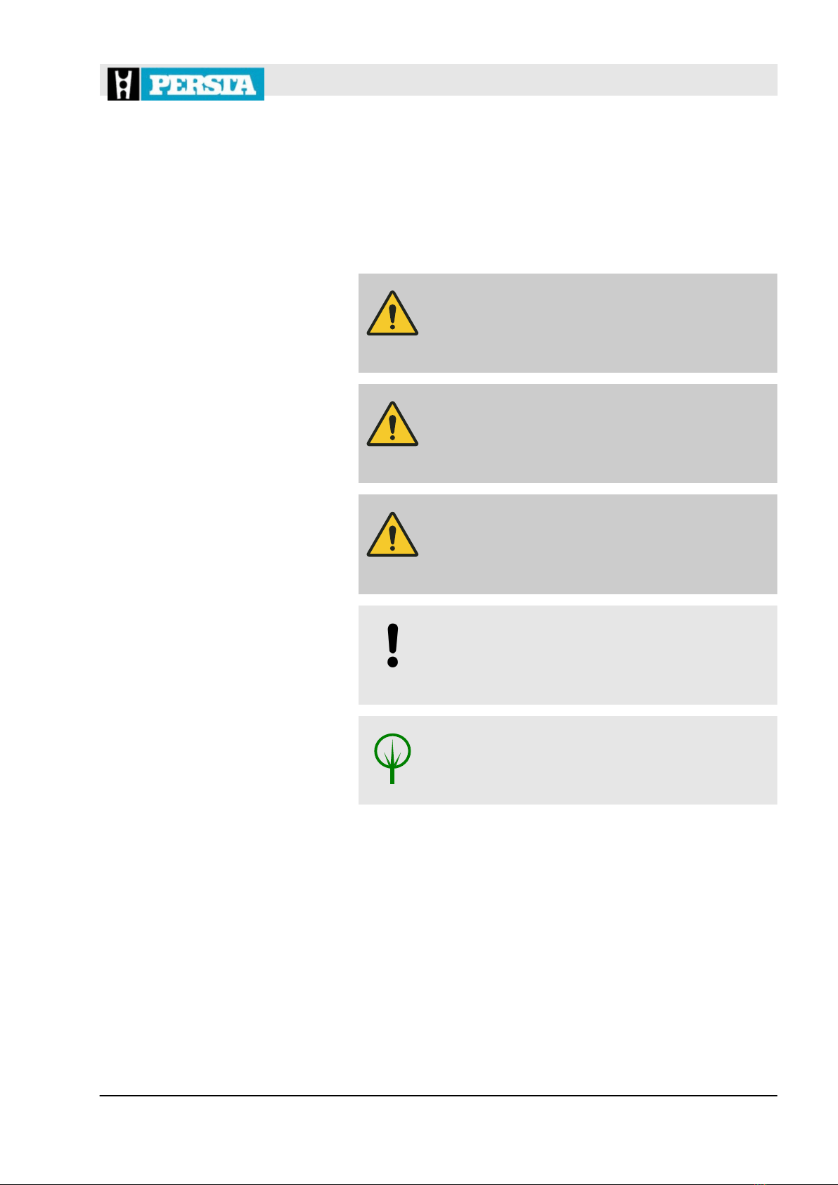
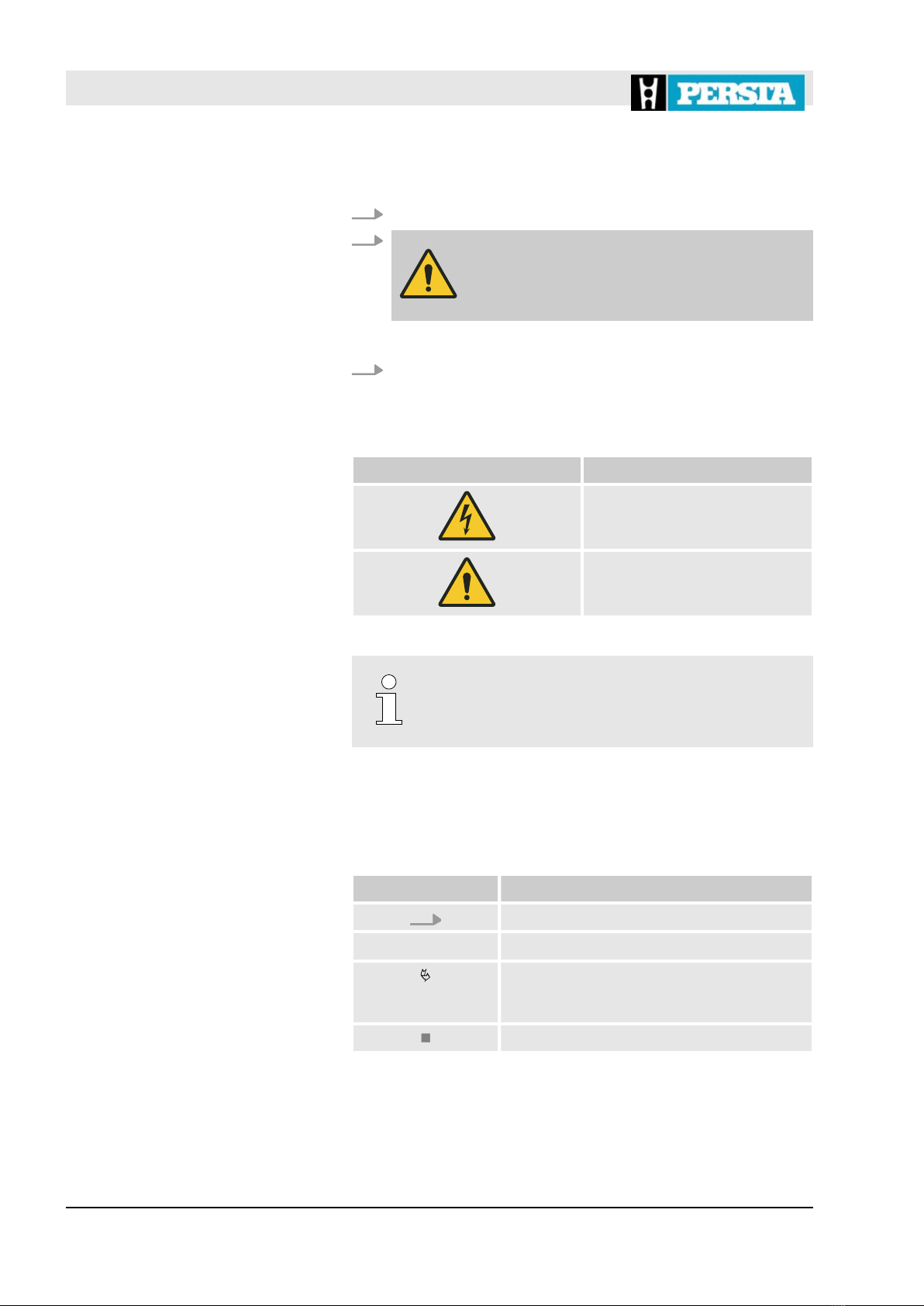
2.1 Symbols in this manual................................................. 9
2.2 Intended use............................................................... 11
2.3 Safety signs................................................................ 12
2.4 Safety devices............................................................ 14
2.5 Residual risks............................................................. 17
2.5.1 Basic dangers at the workplace............................... 17
2.5.2 Electric shock hazard............................................... 18
2.5.3 Danger due to hydraulics......................................... 18
2.5.4 Hazards associated with the pneumatic system...... 19
2.5.5 Mechanical hazards................................................. 19
2.5.6 Thermal dangers...................................................... 20
2.5.7 Dangers due to hazardous substances and oper-
ating materials......................................................... 20
2.6 Behaviour in the event of an emergency.................... 22
2.7 Personnel requirements.............................................. 22
2.8 Responsibility of the operating company.................... 24
2.9 Personal protective equipment................................... 25
2.10 Spare parts............................................................... 27
2.11 Environmental protection.......................................... 28
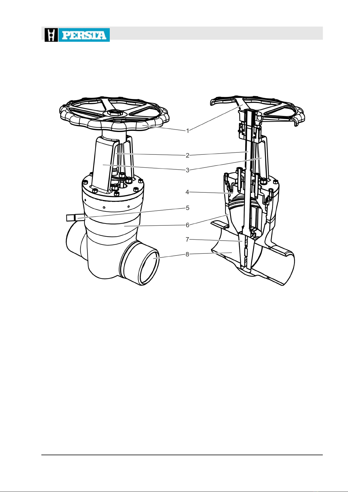
3 Functional description..................................................... 29
3.1 Mode of operation of the high pressure gate valve..... 29
3.2 Seal to the outside...................................................... 30
3.3 Versions of the high pressure gate valve ................... 31
3.3.1 Shut-off element....................................................... 31
3.3.2 Actuator variants...................................................... 33
3.3.3 Display elements..................................................... 36
3.3.4 Connections............................................................. 36
4 Transport and storage...................................................... 39
4.1 Safety instructions for transport and storage.............. 39
4.2 Transport of packages................................................ 40
4.3 Storage of the valve.................................................... 41
4.4 Storage of spare parts................................................ 41
5 Installation......................................................................... 43
5.1 Safety instructions for installation............................... 43
5.2 Before the installation................................................. 45
5.3 Installing the valve...................................................... 46
5.4 Attaching additional safety devices............................. 46
5.5 For electric actuators, connect the power supply....... 47
5.6 For a hydraulic actuator, connecting the hydraulic
system........................................................................ 47
Table of contents
20.05.2021 High Pressure Gate Valves DSK and DSP 5

5.7 For a pneumatic actuator, connecting the pneumatic
system........................................................................ 48
5.8 After the installation.................................................... 48
5.8.1 Pickling the valve..................................................... 49
5.8.2 Painting the valve.................................................... 49
5.8.3 Executing a system pressure test and leak test...... 50
5.8.4 Applying thermal insulation...................................... 50
6 Initial start-up.................................................................... 53
6.1 Safety instructions for commissioning........................ 53
6.2 Prior to commissioning............................................... 56
6.3 Executing the commissioning process........................ 57
7 Operation........................................................................... 59
7.1 Safety instructions for operation................................. 59
7.2 Operating the valve..................................................... 61
7.2.1 Valve with manual actuator (handwheel)................. 61
7.2.2 Valve with electric actuator...................................... 61
7.2.3 Valve with hydraulic or pneumatic actuator ............ 62
7.3 Operating the valve in an emergency......................... 63
7.3.1 Valve with manual actuator (handwheel)................. 63
7.3.2 Valve with electric actuator...................................... 64
7.3.3 Valve with hydraulic or pneumatic actuator............. 65
8 Maintenance...................................................................... 67
8.1 Safety instructions for maintenance............................ 67
8.2 Maintenance schedule................................................ 71
8.3 Maintenance tasks...................................................... 72
8.3.1 Visually checking the valve...................................... 72
8.3.2 Replacing the gland packing.................................... 72
8.3.3 Replacing the gasket of the pressure sealing
bonnet...................................................................... 77
8.3.4 Lubricating moving parts (stem thread)................... 81
8.4 After maintenance....................................................... 82
9 Faults and troubleshooting.............................................. 83
9.1 Safety notices for fault correction............................... 83
9.2 Fault table................................................................... 86
10 Dismantling, disposal....................................................... 89
10.1 Safety notice for dismantling and disposal............... 89
10.2 Dismantling............................................................... 92
10.3 Disposal.................................................................... 93
11 Index................................................................................... 95
Table of contents
20.05.2021High Pressure Gate Valves DSK and DSP6

1 Overview
Fig. 1: High pressure gate valve (shown here: DSK 10 series)
1 Actuator (in the example: handwheel)
2 Stem
3 Bonnet
4 Pressure sealing bonnet
5 Nozzle for over pressure safety device (optional)
6 Body
7 Shut-off element (in the example: flexible discs)
8 Flow passage
The valves called high pressure gate valves are installed in pipes.
The body (Fig. 1/6) of the valve is flanged or welded in the pipe-
work, depending on the version.
The shut-off element is moved up and down via the stem (Fig. 1/2).
When the shut-off element (Fig. 1/7) is moved down into the flow
passage, no medium can flow through the valve. When the valve is
open, the medium flows through the entire body.
See
Ä
Chapter 3 “Functional description” on page 29.
Overview – high pressure gate
valves
Brief description
Overview
20.05.2021 High Pressure Gate Valves DSK and DSP 7

The models DSK and DSP differ in the type of shut-off element:
nDSK: flexible disc gate valve
nDSP: parallel discs
See
Ä
Chapter 3.3.1 “Shut-off element” on page 31.
The stem is moved differently depending on the version:
nmanually via handwheel
nelectrically
nhydraulically
nPneumatically
See
Ä
Chapter 3.3.2 “Actuator variants” on page 33.
Depending on the version of the high pressure gate valve, it is suit-
able for use with water, steam, oil and other non-aggressive media.
The following tools are required for the tasks described in the oper-
ating instructions:
Forklift
Forklift with sufficient load-bearing capacity for transport of valves.
Hoist
Hoist with sufficient load-bearing capacity for transporting valves
and components.
Packing extractor
Tool for removing gland packing elements.
Pin puncher
Mandrel-like tool for punching out the segment rings.
Sling gear
Functional and approved gear for attaching valves and compo-
nents on the hoist.
Shut-off element
Actuator variants
Media
Tools
Overview
20.05.2021High Pressure Gate Valves DSK and DSP8

2 Safety
2.1 Symbols in this manual
Safety instructions are indicated by symbols in this manual. The
safety instructions are introduced by signal words that indicate the
scope of the hazard.
DANGER!
This combination of symbol and signal word indi-
cates a hazardous situation that, if not avoided, will
result in death or serious injury.
WARNING!
This combination of symbol and signal word indi-
cates a potentially hazardous situation that, if not
avoided, may result in death or serious injury.
CAUTION!
This combination of symbol and signal word indi-
cates a potentially hazardous situation that, if not
avoided, may result in minor or moderate injury.
NOTICE!
This combination of symbol and signal word indi-
cates a potentially hazardous situation that, if not
avoided, may result in damage to property.
ENVIRONMENT!
This combination of symbol and signal word indi-
cates potential hazards for the environment.
Safety instructions may refer to specific, individual instructions.
Such safety instructions are integrated into the specific instruction,
so that the flow of reading is not interrupted during performance of
the task. The signal words described above are used.
Safety instructions
Safety instructions in specific
instructions
Safety
Symbols in this manual
20.05.2021 High Pressure Gate Valves DSK and DSP 9

Example:
1. Loosen the bolt.
2.
CAUTION!
Risk of getting trapped by the cover!
Close the cover carefully.
3. Tighten the bolt.
The following symbols are used in the safety instructions to indi-
cate special hazards:
Warning signs Type of danger
Warning – high-voltage.
Warning – danger zone.
This symbol indicates useful tips and recommen-
dations as well as information on efficient and
trouble-free operation.
The following symbols are used throughout these instructions to
highlight specific instructions, results, lists, references and other
elements:
Symbol Explanation
Step-by-step instructions
ðResults of an action
References to sections of these operating
instructions and other applicable docu-
ments
Lists without a defined sequence
Special safety instructions
Tips and recommendations
Additional symbols
Safety
Symbols in this manual
20.05.2021High Pressure Gate Valves DSK and DSP10

2.2 Intended use
Valves of the specified series (
Ä
“Scope of the document”
on page 3) are designed for installation in pipes under the fol-
lowing conditions:
nOperation of the valve as an open/close valve.
nOperation of the valve with liquid or gaseous media, without
particular corrosive, chemical or abrasive impact.
nTemperature change speeds of approx. 3–6 K/min (3–6 °C/
min).
nMaximum number of 1000 load cycles between a depressur-
ised state and the maximum permissible pressure PS.
nAny number of load cycles at pressure fluctuations of up to
10 % of the maximum permissible pressure PS.
nGenerally used flow rates depending on the type of medium
and the application for which the valve is used.
nOperation of the valve without additional external influences,
such as pipe forces, vibrations, wind loads, earthquakes, cor-
rosive environments, fires, traffic loads, decomposition pres-
sures of unstable fluids.
nOnly operate the valve within the limits specified on the type
plate (
Ä
“Rating plate” on page 13).
nIf the valve is operated in the creep range, the valve is
designed for a maximum operating time of 100,000 h. The
valve must be replaced afterwards.
nNo temperature increases were considered. In case of use in
the hot vapour area, temperature increases must be consid-
ered according to the regulations of the operating company.
nThe test pressure for a recurring test must not exceed the
maximum permitted pressure PS multiplied by 1.3.
nThe valve may only be operated if internal pressure loading is
predominantly dormant. Additional loads (e.g. stationary
thermal stress, unsteady pressure and temperature loads in
case of alternating loads or pipe loads) were not considered.
When using the valve in potentially explosive areas, observe
instructions contained in the ignition hazard assessment GA004
and implement the measures it stipulates.
Intended use includes compliance with all the information con-
tained in this manual.
Any use that deviates from the intended use or any other form of
use constitutes misuse.
Safety
Intended use
20.05.2021 High Pressure Gate Valves DSK and DSP 11

WARNING!
Danger in the event of misuse!
Misuse of the valve can cause dangerous situa-
tions.
– Never use the valve in potentially explosive
areas without complying with the instructions
and measures contained in the ignition hazard
assessment GA004.
– Do not use the valve to regulate the mass flow.
– Do not use any objects to increase the force
applied when using the handwheel.
– Only operate the handwheel by hand.
– If the handwheel does not move smoothly, or if it
cannot be activated, contact the manufacturer.
– Connect the pipes so that they are free of ten-
sion.
– Pay attention to the correct installation position
of the valve.
– Do not use valves as an anchor point.
– Never run the electric actuators with excess
torque.
– Do not exceed the number of permitted load
cycles (
Ä
Chapter 2.2 “Intended use”
on page 11).
– When operating a valve with:
– an equalizing pipe
– a bore in the disc or
– a bore in the seat ring
as a safety device (
Ä
Chapter 2.4 “Safety
devices” on page 14), only operate the valve in
one direction (
Ä
“Flow direction arrow”
on page 13).
2.3 Safety signs
The following symbols and instruction signs are in the work area.
These symbols and instruction signs refer to the immediate vicinity
in which they are affixed.
Misuse
Safety
Safety signs
20.05.2021High Pressure Gate Valves DSK and DSP12

WARNING!
Danger if signs are illegible!
Over time, stickers and signs can become fouled
or can become illegible in some other manner, so
that dangers are not recognised and necessary
operating instructions cannot be complied with.
This results in a danger of injury.
– Keep all safety, warning, and operating instruc-
tions that are affixed to the device in legible con-
dition.
– Replace damaged signs or stickers immediately.
The rating plate is on the valve. Depending on the version, the fol-
lowing information is on the rating plate:
nConfirmation number
nArticle number
nYear of manufacture
nNominal diameter
nNominal pressure/design data
Depending on the version, the flow direction is marked with an
arrow on the valve.
Additional markings (e.g. max. temperature limits) are available on
customer request.
Rating plate
Flow direction arrow
Customer-specific markings
Safety
Safety signs
20.05.2021 High Pressure Gate Valves DSK and DSP 13

2.4 Safety devices
Fig. 2: Division into “chambers”
In the closed position, there are 3 “chambers” in the valve:
1st chamber: pressurized side (Fig. 2/1)
2nd chamber: non-pressurized side (Fig. 2/2)
3rd chamber: shut-off inner chamber (Fig. 2/3)
Have the operating company safeguarded the 3rd
chamber against overloading.
Safety
Safety devices
20.05.2021High Pressure Gate Valves DSK and DSP14

Depending on the application, the valve (Fig. 3/1) can be equipped
with an external over pressure safety device by the operating com-
pany. In this regard, the valve can delivered with a sealed nozzle
from the manufacturer (Fig. 3/2). The nozzle creates a connection
from the outside to the 3rd chamber (Fig. 2/3). External over pres-
sure safety devices can be attached to the nozzle (Fig. 3/2).
With a bypass, additional external valves (Fig. 4/1) can establish
connections between chambers (Fig. 3) within a valve that are sep-
arated from each other.
NOTICE!
Risk of damage to property due to closed
bypass valves!
The high pressure valve can be damaged if both
bypass valves are closed.
– Ensure that at least one of the two bypass
valves is open at all times.
Optional connection for external
safety devices
Fig. 3: Closed nozzle on the body
External safety device: bypass with
equalizing pipe
Fig. 4: Bypass with equalizing pipe
(shown here: DSK 25 50–600)
Safety
Safety devices
20.05.2021 High Pressure Gate Valves DSK and DSP 15

An equalizing pipe (Fig. 5/1) is used to create a connection
between the 3rd chamber (Fig. 2/3) and the pressurised side
(Fig. 2/1 of the valve.
WARNING!
Risk of injury from alternating flow direction!
There is a risk of serious injury if the specified flow
direction is not complied with when an equalizing
pipe is used to protect the valve.
– Only operate the valve in the permitted flow
direction (
Ä
“Flow direction arrow” on page 13).
A safety valve (Fig. 6/1) attached to the nozzle (Fig. 3/2) dissipates
critical pressures.
An optional bore in the disc prevents pressure in the body from
exceeding the operating pressure of the valve.
WARNING!
Risk of injury from alternating flow direction!
There is a risk of serious injury if the specified flow
direction is not complied with when a bore in the
disc is used to protect the valve.
– Only operate the valve in the permitted flow
direction (
Ä
“Flow direction arrow” on page 13).
Equalizing pipe
Fig. 5: Equalizing pipe
Safety valve
Fig. 6: Safety valve
Bore in the disc
Safety
Safety devices
20.05.2021High Pressure Gate Valves DSK and DSP16

An optional bore in the seat ring prevents pressure in the body
from exceeding the operating pressure of the valve.
WARNING!
Risk of injury from alternating flow direction!
There is a risk of serious injury if the specified flow
direction is not complied with when a bore in the
seat ring is used to protect the valve.
– Only operate the valve in the permitted flow
direction (
Ä
“Flow direction arrow” on page 13).
On an electric actuator, torque switches are installed in addition to
the limit switch. The torque switches protect the valve from exces-
sive torque.
2.5 Residual risks
The valve has been developed and manufactured to the state-of-
the-art and in accordance with generally accepted rules of safety.
Nevertheless residual risks remain that require careful handling.
The residual risks and the resulting behaviours and measures are
listed below.
2.5.1 Basic dangers at the workplace
DANGER!
Life-threatening danger due to failure to
comply with the rules of behaviour specified
for hazardous areas!
Depending on the version the valve can be used in
hazardous areas. There is life-threatening danger
if the rules of behaviour are not complied with
within these areas.
– Ensure that tasks on the valve can be executed
at the installation site.
Bore in the seat ring
Torque switch on an electric
actuator
Hazardous areas
Safety
Residual risks > Basic dangers at the workplace
20.05.2021 High Pressure Gate Valves DSK and DSP 17

CAUTION!
Danger of injury due to tripping up!
There is a danger of fall injuries in the area of use
of the valve.
– Install cable and connection lines in such a
manner that there are no trip hazards.
2.5.2 Electric shock hazard
DANGER!
Risk of fatal injury from electric shock!
There is a risk of fatal injury when touching live
components of the actuator. Switched-on electrical
components can execute uncontrolled movements
and can cause serious injuries.
– Prior to starting work, switch off the supply of
electricity and definitively disconnect it.
– Only have an electrician perform tasks on elec-
trical lines and components.
2.5.3 Danger due to hydraulics
WARNING!
Danger of injury due to hydraulic energy!
Hydraulically-powered components of the valve, as
well as the triggering of the overpressure valve can
cause severe injuries.
– Only have specialised personnel perform tasks
on the hydraulic system.
– Prior to starting the tasks on the hydraulic
system ensure that it is completely depressur-
ised. Completely depressurise pressure accu-
mulators.
– Operate the valve in a frost-free environment to
prevent the body from bursting.
– Wear personal protective equipment.
Trip hazard
Electric shock
Fluid under high pressure
Safety
Residual risks > Danger due to hydraulics
20.05.2021High Pressure Gate Valves DSK and DSP18

2.5.4 Hazards associated with the pneumatic system
WARNING!
Danger of injury due to pneumatic energy!
Pneumatically-powered components of the valve,
can cause severe injuries.
– Only have pneumatic specialists perform tasks
on the pneumatic equipment.
– Prior to starting the tasks on the pneumatic
equipment ensure that it is completely depres-
surised. Completely depressurise pressure
accumulators.
– Wear personal protective equipment.
2.5.5 Mechanical hazards
WARNING!
Danger of injury on moving parts!
Danger of injury exists on moving parts (stems/
anti-twist devices).
– When the valve is in operation do not grasp
moving parts.
– Wear personal protective equipment.
WARNING!
Danger of injury due to the heavy weight of the
valve!
The heavy weight of the valve, and of its compo-
nents, can result in severe injuries.
– Transport valves with a suitable hoist or forklift.
– Don not lift valves via the handwheel.
– Do not lift valves via the actuator.
– If possible, lift valves via the bonnet.
– Use approved and functional sling gear.
– Safeguard valves and components from falling
over.
Hazards associated with the pneu-
matic system
Danger of crushing on stems
Heavy weight of the valve
Safety
Residual risks > Mechanical hazards
20.05.2021 High Pressure Gate Valves DSK and DSP 19

2.5.6 Thermal dangers
WARNING!
Danger of injury due to high/low temperatures!
Depending on the insert of the valve or of the pipe,
injuries can occur due to the high or low tempera-
ture of the components.
– When working on components or activating final
control equipment, wear protective equipment:
Protective gloves, protective goggles.
– Prior to performing tasks on these components,
allow them to cool down/warm up to ambient
temperature.
– Have the protective insulation provided by the
operating company attached.
WARNING!
Danger of injury due to pipes shattering at
freezing temperatures!
As a result of pipes shattering at freezing tempera-
tures, severe injuries can be caused by fluid under
high pressure.
– Ensure that the valve is completely empty
before it is taken out of service.
– Never operate valves at temperatures close to,
or below the freezing point of the pumping
medium.
2.5.7 Dangers due to hazardous substances and operating materials
WARNING!
Danger of injury due to pumping medium under
pressure!
In operating status, as well as in decommissioned
status, depending on the version of the valve, inju-
ries can occur due to medium escaping under high
pressure.
– Do not unscrew threaded connections.
– If threaded connections are loose, inform the
operating company and have the pipe section in
question shut-off.
– If threaded connections are loose have the
cause for this clarified and eliminated. If neces-
sary have the manufacturer check the valve.
Thermal dangers
Danger of freezing
Pumping medium
Safety
Residual risks > Dangers due to hazardous substances and operating materials
20.05.2021High Pressure Gate Valves DSK and DSP20
This manual suits for next models
3
Table of contents
Other PERSTA Control Unit manuals
Popular Control Unit manuals by other brands

Armstrong
Armstrong OB-2000PT Integral Assembly instructions

Grundfos
Grundfos CIM 280-EU GIC Gen2 instructions

Telit Wireless Solutions
Telit Wireless Solutions GL865 V3 user guide

Riello
Riello MO550 manual

Honeywell
Honeywell JADE W7220 installation instructions

Ascon tecnologic
Ascon tecnologic PM74 user manual

Panasonic
Panasonic SF-C14EX-01 instruction manual

Solid State Logic
Solid State Logic SiX Channel 500 Series user guide

Viessmann
Viessmann 5222 Operation manual

Girard Systems
Girard Systems 98GC1102 Installation & programming guide

Thermomax
Thermomax SA132 Instruction leaflet

AirCom
AirCom DBM operating instructions