AS-TF222-156EN
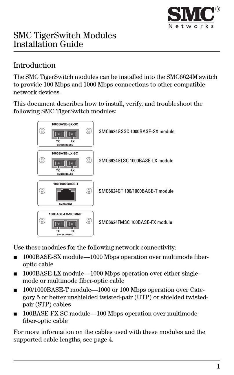
Page 1 of 2
Locked Unlocked
Instruction Manual
Compact Speed Control Valve with Pilot check
valve
ASP Series
Without residual
pressure release
function
With residual
pressure release
function
The intended use of this product is for a temporary stop of an actuator. When
a pilot signal is applied, the valve closes the flow from 2 to 1, and the actuator
comes to a stop. Once the pilot signal has been removed, the flow path from 2
to 1 opens. The manual override button opens all flow paths (2→1, 21 and
exhaust port).
1 Safety Instructions
These safety instructions are intended to prevent hazardous situations and/or
equipment damage. These instructions indicate the level of potential hazard
with the labels of “Caution,” “Warning” or “Danger.”
They are all important notes for safety and must be followed in addition to
International Standards (ISO/IEC)
*1)
, and other safety regulations.
*1)
ISO 4414: Pneumatic fluid power - General rules relating to systems.
ISO 4413: Hydraulic fluid power - General rules relating to systems.
IEC 60204-1: Safety of machinery - Electrical equipment of machines.
(Part 1: General requirements)
ISO 10218-1: Robots and robotic devices - Safety requirements for industrial
robots - Part 1: Robots.
•Refer to product catalogue, Operation Manual and Handling Precautions for
SMC Products for additional information.
•Keep this manual in a safe place for future reference.
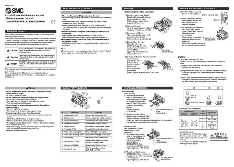
Warning
•Always ensure compliance with relevant safety laws and standards.
•All work must be carried out in a safe manner by a qualified person in
compliance with applicable national regulations.
2 Specifications
2.1 General specifications
Model ASP
Fluid Air
Proof pressure 1.05 MPa
Max. operating pressure 0.7 MPa
Min. operating pressure 0.1 MPa
Min. air quality
5 µm filtration or smaller
Ambient and fluid temperature
-5 to +60 C° (No freezing)
Pilot check valve operating
pressure
Note 5)
More than 50% of operating pressure
(0.1 MPa or more)
Applicable tubing material
Nylon, Soft nylon, Polyurethane
Min. operating frequency Every 30 days
Max. operating frequency 2 Hz
Impact Resistance
1000 m/s
half sine 6 ms
Vibration Resistance
0.35 mm 10 to 150 Hz
Table 1.
2 Specifications - Continued
Note 1) Use with air [6:4:4] or better as defined in ISO08573-1:2010. If used
with air not satisfying at least the air purity classes [6:4:4] defined in ISO8573-
1:2010 Compressed air – Part 1: Contaminants and purity classes, ASP may
not operate properly, disturbing safe operation of the system.
Note 2) Use caution about the maximum operating pressure when soft nylon
and polyurethane is used.
Note 3) No malfunction of the valve occurred when two axes (horizontal and
vertical) and two directions were tested and (pulse shape: sinusoidal), 3 times
(test sample mounted with bracket). (IEC 60068-2-27:2009)
Note 4) No malfunction occurred in a sweep cycle test from 10 to 150 Hz at a
vibration sweep 0.35mm. The test was performed in two axes (horizontal and
vertical) and two directions, 7 min per cycle (20 cycles). (IEC 60068-2-6:2007)
Note 5) For ASP-*-M5/U10, pilot check valve, pressure must be more than 50%
of operating pressure and 0.15 MPa or more.
2.2 Design / Selection
Warning
•This product cannot be used for accurate and precise intermediate
stops of the actuator.
Due to the compressibility of air as a fluid, the actuator will continue to move
until it reaches a position of pressure balance, even though the pilot check
valve closes with an intermediate stop signal.
•This product cannot be used to hold a stop position for an extended
period of time.
Pilot check valves and actuators are not guaranteed for zero air leakage.
Therefore, it is sometimes not possible to hold a stop position for an extended
period of time. In the event that holding for an extended time is necessary, a
mechanical means for holding should be devised.
•To exhaust air manually, press the black button on body.
If the valve connected to port 1 is not open, the pressure in the cylinder will
not be able to exhaust.
•Consider the release of residual pressure.
Actuators may move suddenly due to residual pressure, which can be
dangerous during maintenance procedures.
•When used in a balance control circuit, there are instances in which the
check valve cannot release, even though the pilot pressure is 50% of
the operating pressure. In these cases the pilot pressure should be the
same as the operating pressure.
•The check valve, by design is closed by the differential pressure
generated.
If the differential pressure between the inlet (port 1) and outlet (port 2) is less
than the minimum operating pressure, the check valve will not close
completely, causing a leakage.
•In the following cases, abnormal noise may occur due to poor exhaust
or oscillation.
・When there is residual pressure or back pressure on port 1 (IN) side.
・When the differential pressure between port 1 and port 2 side is smaller
than the minimum working pressure.
・When the effective cross-sectional area of the IN side piping / on-off valve
(ASP) of the product is smaller than the effective cross-sectional area of the
product.
・When the pressure loss on port 1 side during product (ASP) operation is
slower than the pressure loss on port 2 side.
・When the supply pressure of the PIL port is throttled.
・When port 1 (IN) side piping (tube) is bent or crushed.
•Do not allow the product to constantly rotate when using. Do not allow a
moment load to be applied when using the product.
•Please note that the valve may open if the pressure difference between the
inlet pressure and the outlet pressure becomes small due to internal leakage.
Warning
Special products (-X) might have specifications different from those shown in
this section. Contact SMC for specific drawings.
3 Installation
3.1 Installation
Warning
•Do not install the product unless the safety instructions have been read and
understood.
3 Installation - continued
3.2 Environment
Warning
•Do not use in an environment where corrosive gases, chemicals, salt water
or steam are present.
•Do not use in an explosive atmosphere.
•Do not expose to direct sunlight. Use a suitable protective cover.
•Do not install in a location subject to vibration or impact in excess of the
product’s specifications.
•Do not mount in a location exposed to radiant heat that would result in
temperatures in excess of the product’s specifications.
3.3 Piping
Caution
•Before connecting piping make sure to clean up chips, cutting oil, dust etc.
•When installing piping or fittings, ensure sealant material does not enter
inside the port. When using seal tape, leave 1 thread exposed on the end of
the pipe/fitting.
•Ensure to screw into correct threads: R screws into Rc threads, NPT screws
into NPT threads and G screws into G thread.
•Check piping directions before mounting.
Connect the inlet to the directional control valve and the outlet to the actuator.
•Do not apply excessive force or impact by a tool to the cover (pilot port),
fittings and other parts of the product. Do not apply an external force such as
moment, torsion, or tensile, to the fittings of the cover during and after
mounting the cover (pilot port).
•Depending on the piping orientation, products will either have a hexagonal
hole or flats to screw the product in.
To install and remove the product with hexagonal hole, use an appropriate
hex key and push it into the hexagon hole of the stud.
•Using the appropriate hex key, given in the table above, tighten the fitting to
the proper tightening torque.
3.4 Lubrication
Caution
•SMC products have been lubricated for life at manufacture, and do not
require lubrication in service.
•If a lubricant is used in the system, refer to catalogue for details.
4 Settings
4.1 Speed controller
•The speed controller’s controlled flow values are with the needle fully open
(2 to 1) and free flow with the needle fully closed (1 to 2).
•The products in this manual are retainer type so that the needle is not
removed completely. Over rotation will cause damage.
•Adjust the speed by opening the needle slowly from the fully closed state.
Loose needle valves may cause unexpected sudden actuator lurching.
4Settings – Continued
When a needle valve is turned clockwise, it is closed and actuator speed
decreases. When a needle valve is turned counterclockwise, it is open and
actuator speed increases.
•This product has a stopper for when the knob reaches the fully closed
position. Excess torque may break the stopper.
Table below shows the maximum allowable torque of the knob.
•Do not use tools such as pliers to rotate the knob. It can cause idle rotation
or damage the knob.
•After pushing the knob down to lock, confirm that it is locked. It should not be
possible to rotate the knob to the right or to the left. If the knob is pulled with
force, it may break. Do not pull the knob with excessive force.
4.2 Pressure release
•Use a tool to push the manual override button fully. See the table below for
the depth and force to push the tool. The higher the residual pressure, the
more force is needed to press the override button completely.
•Ensure that the manual override button is back to its original position after
pushing the button (at the end face of the product) before use. The check
valve doesn’t work properly unless the button is back to the original position.
Replace the product if the button is unable to return to the original position.
5 How to Order
Refer to drawings or catalogue for ‘How to Order’.
6 Outline Dimensions
Refer to drawings or catalogue for outline dimensions.
Caution
Caution indicates a hazard with a low level of risk which, if
not avoided, could result in minor or moderate injury.
Warning
Warning indicates a hazard with a medium level of risk
which, if not avoided, could result in death or serious injury.
Danger
Danger indicates a hazard with a high level of risk which, if
not avoided, will result in death or serious injury.
Connection Thread Hex Key (Nominal)
Metric [mm] Imperial [Inch]
M5, 10-32UNF 2.5 -
R1/8, G1/8 6 -
NPT1/8 - 7/32”
R1/4, G1/4 8 -
NPT1/4 - 5/16”
R3/8, G3/8 10 -
NPT3/8 - 3/8”
R1/2, G1/2 12 -
NPT1/2 - 3/8”
Maximum allowable torque [N·m]
Part number Operating force [N]
(reference value)
Operating depth
[mm]
ASP-*-M5/U10 5.3 to 8.2 3.5
ASP-*-*01 5.1 to 11.9 3.9
ASP-*-*02 6.7 to 19.5 3.8
ASP-*-*03 10.6 to 34.4 4.7
ASP-*-*04 17.1 to 54.4 5.8
Stopper
Contact face of
stopper
