Pfaff creative 4874 User manual

4874
SERVICE MANUAL

TABLE OF CONTENTS
1
A. General directions and recommendations
B. Recommendations
C.1-2. Mechanical sewing disorders
D.1-3. Test program - test of LCD display
E.1-2. Test program - tension settings - fine tuning
F.1-2. Error code
G.1-3. Gauge for the after - sales service
1. Removing back cover
2. Removing front cover
3.a-e. Removing LCD UNIT and connections for Main & LCDPCB
4.a-b. Angular position of balance weights and position of eccentrics
5.a-b. Height and alignment of cloth presser bar
6.a-b. Height and orientation of needle bar in relation to the needle plate holes
7. Height - clearance - angular position of lower looper
8. Clearance of needle guards
9.a-b. Timing of lower looper
10. Angular position of upper looper
11. Clearance and timing of upper looper to lower looper
12.a-d. Chain looper : angular position - clearance - orbital timing - clearance of
chain needles guards
13. Chain looper thread take up rotary cam
14. Height of feed dog
15.a-b. Moving cutter and vertical feed timing
16.a-b. Horizontal feed timing against chainstitch needle
17. Adjustment for differential feed unit operated with stepping motor
18. Position of fixed cutter and cutting width dial setting
19. Position of loopers threads take up lever
20. Position of the stitch width finger
21. Lateral and front covers safety device
22.a-b. Adjustment of setting position for en-sensor and slit-plate
23. Adjustment for stitch length unit operated with step motor
24. Timing adjustment for Top Cover Triangle Thread Guide and Top Cover
Hook
25. Adjustment of threads take up lever for Top cover and Deco cover
26. Installing of Deco unit
27.a-b. Adjustment for Deco unit
28. Cover hem stitch being pulled

TABLE OF CONTENTS 2
29.a-b. Irregular loop formation on the chain needles (cover hems)
30. Cover hem stitch formation (Narrow & Wide)
31. Triple cover hem stitch formation
32.a-c. Top cover stitch formation (Prog.21~23)
33.a-g. Deco cover stitch formation (Prog.24~30)

GENERAL DIRECTIONS AND RECOMMENDATIONS A
Safety
For safety reasons, the sewing machine must be disconnected from the mains:
- Whenever the machine is left unattended
- Whenever preparing the machine for sewing
- Whenever servicing
- Whenever replacing mechanical or electrical parts or accessories
Needles
Usually needles of the system 130/705 H may be used. However, in certain cases stitch
quality may be improved by using type ELX 705 needles.
Choose needle size Nm 80 for sheer materials and Nm 90 for normal or thick materials.
Threads
Choose a good quality polyester thread or blended thread.
Lubrication
Besides the 2 oiling points marked in red, the machine is equipped with self-lubrication
bearings and parts. Lubricate the machine as follows: when using it for the first time - if it
has not been used for some time - when it has been intensively during 7 to 8 hours.

RECOMMENDATIONS B
1. Never connect the machine to a different voltage than tha t marked on the specification
plate.
2. For safety reasons, never perform any repairs on the powe r supply circuit without first
removing the mains lead from the machine.
3. Before replacing the LCD display PCB unit, check by means of the test program.
4. Never plug in or run the machine unless all the connections are correctly set.
5. After replacing the main control PCB unit, it is necessar y to recheck the speeds. Use a
small screwdriver with insulated blade to avoid short-circuits.
6. When changing the light bulb, it is neccessary to disconnect the mains lead.

MECHANICAL SEWING DISORDERS C1
First of all, please refer to the paragraph entitled "maintenance" in the instruction manual,
especially when machine does not turn freely by turning the flywheel by hand. If necessary,
check and adjust tightness of motor belt.
Given below are the most frequent disorders. In most cases, they can be remedied by
checking the adjustments in the following order. However, before checking the adjustments,
make sure that the threading is correct and that all the thread passages are okay.
1. Skipped overlock stitches
Check and adjust if necessary:
- Needle bent or with a dull point - replace needle
- Needle not set correctly - refer to "changing the needle" in the instruction manual
- Burrs on upper or lower looper - polish
- Burrs on stitch tongue - polish
- Excessive tension on the needle thread
- Height and orientation of needle bar
- Clearance between point of lower loopers and needle
- Clearance between upper and lower loopers
- Timing of upper and lower loopers against needle
- Feed timing
2. Skipped chainstitches - Cover hems
Check and adjust if necessary:
- Needle and chain looper thread tensions not balanced
- Needle bent or with a dull point - replace needle
- Needle not set correctly - refer to "changing the needle" in the instruction manual
- Burr on chain looper - replace or polish
- Dull blade edge on moving cutter - replace
- Chain looper needle clearance
- Chain needle guard clearance
- Angular position of chain looper
- Orbital timing of chain looper
- Chain thread take up lever timing
- Height and orientation of needle bar
- Needle plate spring plate bent
-
Clearance and position between back of chain looper and need le L0
Note: For more information, see pages 28-31.
MECHANICAL SEWING DISORDERS C2
3. Thread breakage
Before checking the adjustment, make sure of the good quality of the thread and the needle,
the correctness of threading and the smoothness of all the thread passages. Quite often, an
injury to thread passage is the cause of thread breakage. If all these points are in order, check
the following:
- Dull point of needle or bent needle - replace.
- Dull or burred point of looper - replace.
- Scratch or injury on stitch tongue of needle plate - replace.
- Too strong thread tension.
- Unsmooth or injured edge of needle hole on needle plate (thread breakage of chain stitches)
- replace.
4. Irregular stitches
- Inadequate setting of thread tensions - re-adjust.
- Unsmooth thread passage - polish.
- Height of feed dog.
- Position of looper thread take up levers and thread guides.
- Dull blade edge of moving cutter - replace.
- Injury on needle plate face or presser foot sole - replace.
- Incorrect alignment of pulled-up thread antenna with spool pins - reset it at correct position
to align to spool pins.
5. Breakage of needle
Check and adjust if necessary
- Dull point of needle or bent needle - replace.
- Incorrect placement of needle - refer to "changing the needle" in the instruction manual.
- Clearance of needle guard and (chain needle).
- Incorrect alignment of needle holes of presser foot and needle plate.
- Clearance from needle to lower looper.
- Clearance between the upper and lower loopers.
- Feed timing.
- Horizontal feed timing against chain-stitch needle.
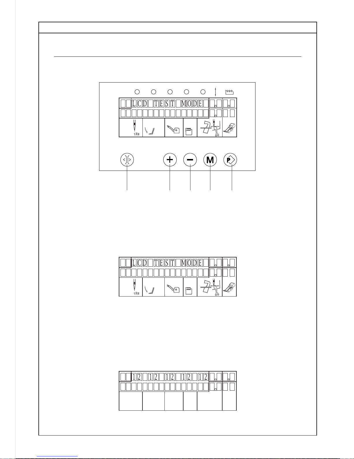
TEST PROGRAM - TEST OF LCD DISPLAY D1
PROG.
1 2 3 45
Access to the test program
1. Switch off the machine.
2. While pressing key "2" and "3" simultaneously, switch on the machine.
3. The matrix pattern turns to "LCD test mode".
4. Press "1", the step motors will rotate to their minimum position and the number "12" will
appear on the display.
Tension value can be checked and adjusted as a manner shown in the page E1.

TEST PROGRAM - TEST OF LCD DISPLAY D2
5. Press "1" again, the step motors will rotate to their maximum position and the number "48"
will appear on the display.
Tension value can be checked and adjusted as a manner shown in the page E1.
6. Press "1" again, the display becomes
7. Press "1" again, the display becomes
8. Press "1" again, the display becomes
9. Press "1" again, the display becomes
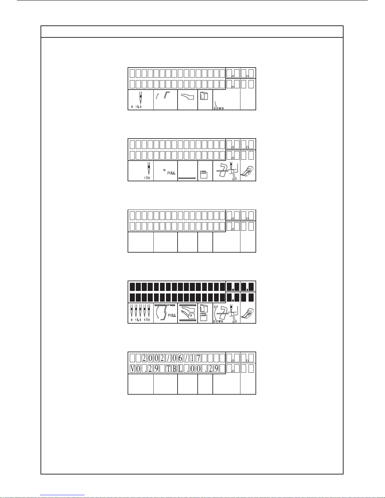
TEST PROGRAM - TEST OF LCD DISPLAY D3
10. Press "1" again, the display becomes
11. Press "1" again, the display becomes
12.Press "1" again, nothing is displayed
13. Press "1" again, all symbols are displayed
14. Press "1" again, Program version number is displayed
Note: It is also possible to proceed with above tests in reverse sequence by pressing key "2"
instead of key "1".
Other manuals for creative 4874
1
Table of contents
Other Pfaff Sewing Machine manuals

Pfaff
Pfaff 487 User manual

Pfaff
Pfaff CREATIVE 2170 PREPARATIONS User manual

Pfaff
Pfaff 242 User manual

Pfaff
Pfaff 3566-2/02 User manual

Pfaff
Pfaff hobbymatic 935 User manual

Pfaff
Pfaff Smart 200c User manual

Pfaff
Pfaff 1245 User manual

Pfaff
Pfaff 1243-712/02 Guide

Pfaff
Pfaff CREATIVE 2.0 - User manual

Pfaff
Pfaff 337 Guide

Pfaff
Pfaff ClassicStyle 1525 User manual

Pfaff
Pfaff Series 3701 Owner's manual

Pfaff
Pfaff 918 User manual

Pfaff
Pfaff tipmatic 1119 User manual

Pfaff
Pfaff Creative 2134 User manual

Pfaff
Pfaff 481 User manual

Pfaff
Pfaff Creative 2140 User manual

Pfaff
Pfaff coverlock 4772 User manual

Pfaff
Pfaff 3734 -12 User manual

Pfaff
Pfaff GrandQuilter 18.8 User manual


