Pfaff PowerLine 2231 Manual

296-12-19 216/002
Aufstellanleitung engl. 02.13
2231
2235
2542
2545
2546
SET-UP INSTRUCTIONS

The reprinting, copying or translation of PFAFF Service Manuals - whether in whole
or in part - is only permitted with our prior consent and with reference to the source.
PFAFF Industriesysteme
und Maschinen AG
Hans-Geiger-Str. 12 - IG Nord
D-67661 Kaiserslautern

Index
Contents ..................................................................................Page
1General Notes ...................................................................................................................... 4
1.01 Explanation of the symbols.................................................................................................... 4
2Scope of delivery ................................................................................................................. 5
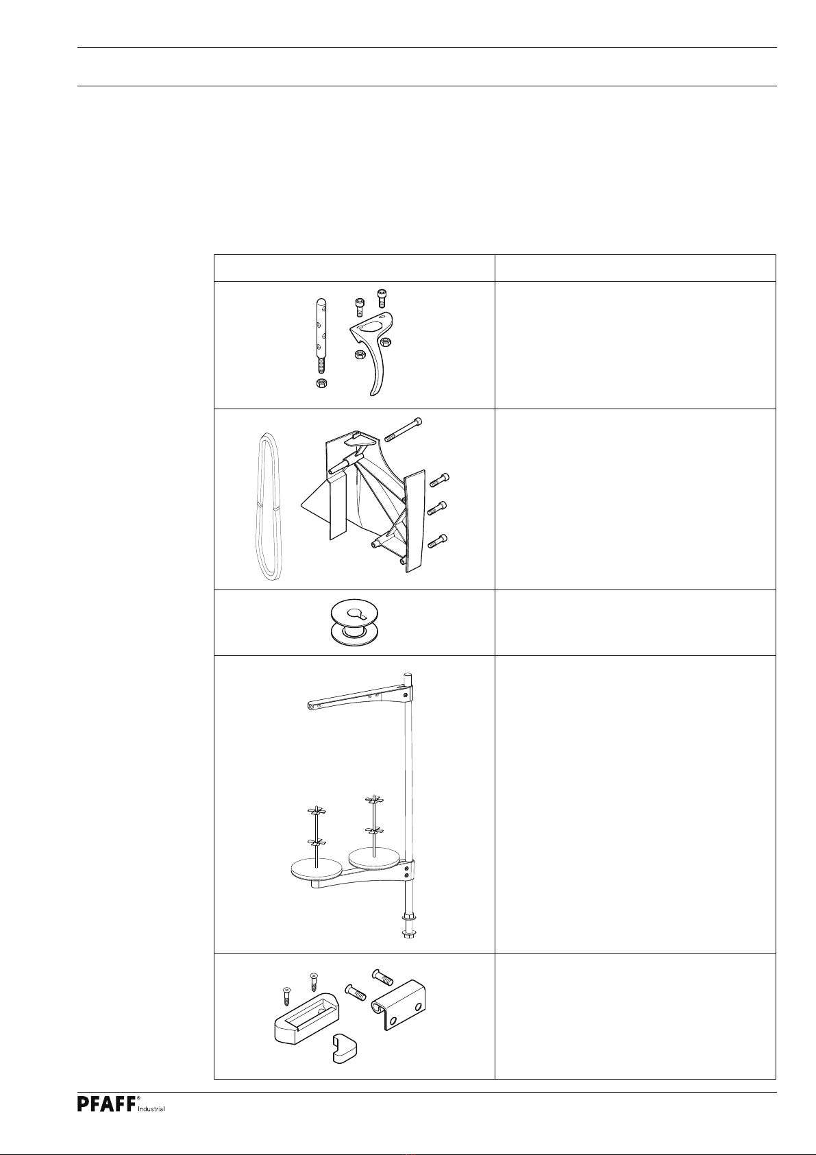
2.01 Sewing machine accessories ................................................................................................5
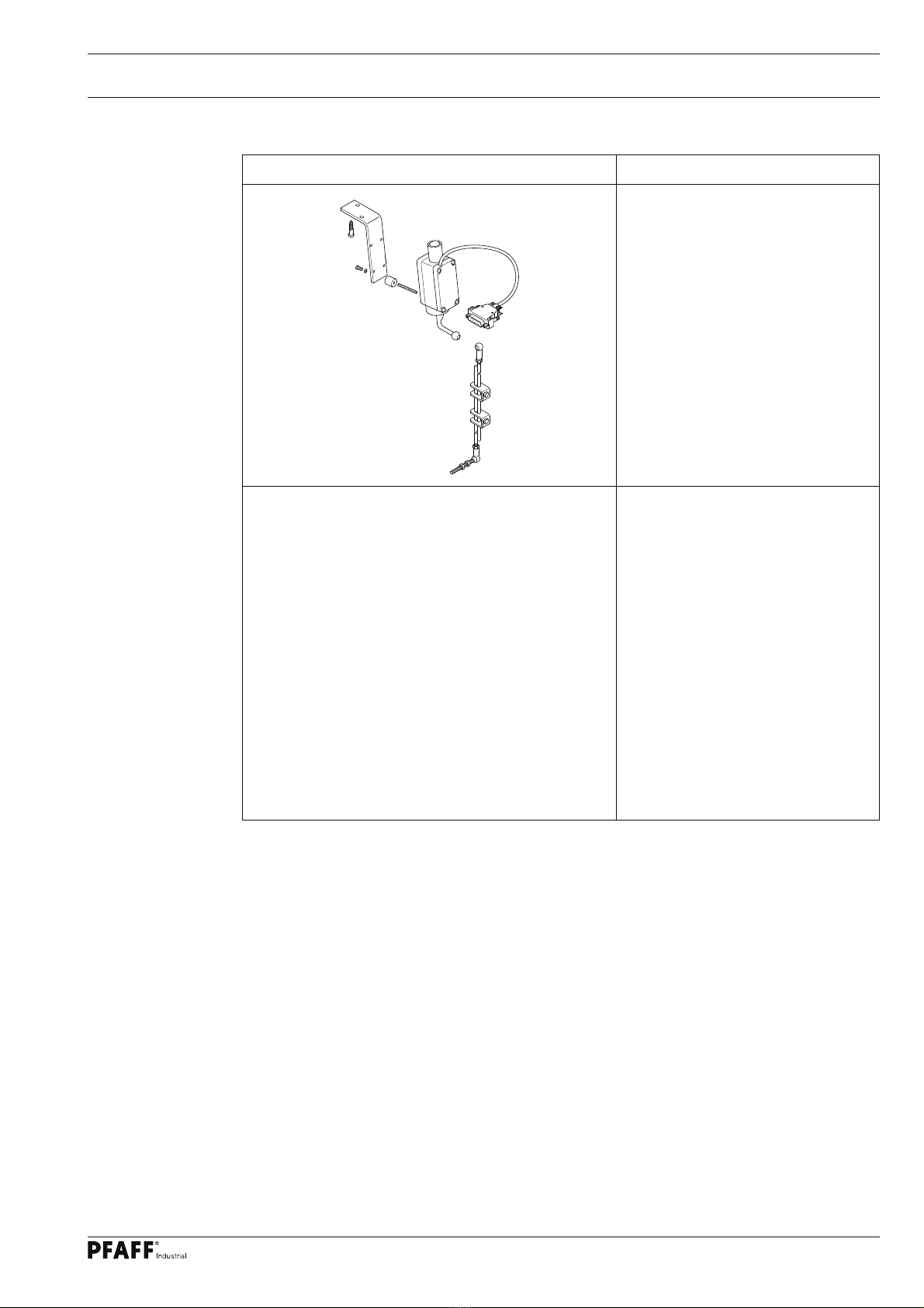
2.02 Accessories for the sewing machine drive with PicoDrive P45 PD2-L .................................. 7
2.03 Accessories for the sewing machine drive with EcoDrive P74 ED-L...................................... 8
3Stand and table top ........................................................................................................... 10
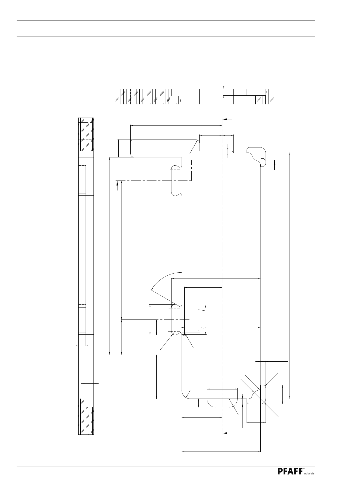
3.01 Table top cutout ................................................................................................................... 10
3.02 Assembly drawing for the table .......................................................................................... 13
3.03 Assembling the stand and table top .................................................................................... 16
3.05 Adjusting the table-top height.............................................................................................. 17
4Assembling the sewing machine drive ............................................................................ 18
4.01 Assembling the motor ......................................................................................................... 18
4.02 Assembling the motor, speedcontrolunit and controlbox .................................................... 19
5LED-Lamp (optional).......................................................................................................... 21
5.01 Assembling the LED lamp ................................................................................................... 21
5.02 Fitting the transformer to the LED lamp .............................................................................. 22
6Installation .......................................................................................................................... 23
6.01 Setting the sewing machine into the stand ......................................................................... 23
6.02 Fitting the V-belt and assembling the bottom belt guard...................................................... 24
6.03 Assembling the thread guide and take-up lever guard......................................................... 25
6.04 Assembling the top V-belt guard and sewing head support................................................. 26
6.05 Mounting the control panel.................................................................................................. 27
6.06 Connecting the plug-in connections and earth cables ......................................................... 28
6.07 Block diagram ...................................................................................................................... 29
6.08 Mounting / connecting the maintenance unit ...............................................................................34
7Commissioning .................................................................................................................. 35
7.01 Switching the machine on/off ..............................................................................................35
7.02 Machine drive home position...............................................................................................36

4
1 General Notes
The machine may only be set-up and commissioned by qualified personnel!
All notes in Chapter 1Safety of the Instruction Manual must be observed!
There must be suitable electrical connections at set-up site, see Chapter 3
Specifications of the Instruction Manual. A firm, level surface and adequate
lighting must also be available at the set-up site.
If the machine was delivered without a table, both the stand and the table top
intended for use must be constructed for a weight of at least 100 kilos.
1.01 Explanation of the symbols
In these Set-Up Instructions, symbols emphasize operations to be carried out or
important information. The symbols used have the following meaning:
Note, information
Service, repair, adjustment, maintenance
(work to be carried out by qualified staff only
Safety symbols
Danger!
Points to be observed.
Danger of injury for operating and specialist personnel!
General Notes

5
2 Scope of delivery
The scope of delivery of the machine depends on the order.
Before setting up the machine, check whether all the required parts have been included.
The following description only applies to one special sewing machine, for which all individual
components have been delivered by the PFAFF Industriesysteme und Maschinen AG.
2.01 Sewing machine accessories
Sewing machine accessories Description / No. of pieces
Thread guide and take-up lever guard
with screws and nuts (1x)
V-belt and
belt guard with screws (1x)
Bobbin (5x)
Reel stand complete (1x)
Rear rubber pads with screws
Front rubber pads
Hinge with screws
Scope of delivery

6
Sewing machine accessories Description / No. of pieces
Sewing head support (1x),
Tilt lock (1x)
(only on the PFAFF 2542, 2545 and 2546)
Oil pan with screws and washers
Industrial
Oilcan (1x),
Sachet with 80 ml oil,
Dusting brush (1x)
Sewing head protective cover (1x)
Allan key 3mm (1x),
Screwdriver large (1x),
Screwdriver small (1x)
Control panel bracket
(with motor AB 321 + PF 321 only)
Set-up instructions,
instruction manual for the machine
Earth cable 2231 + 2235 (2x), 2542, 2545
and 2546 (3x) , screw and washers
Scope of delivery

7
Control package PicoDrive P45 PD2-L Description
Motor mounting with motor and
fastening screws
Control box with fastening
screws
ABCD
F1
+
-
TE
PM
Control panel bracket with control
panel and fastening screws
Speed control unit with holder
and fastening screws, and
connecting rod to the pedal
Scope of delivery
2.02 Accessories for the sewing machine drive with PicoDrive P45 PD2-L

8
Control package EcoDrive P74 ED-L Description
Motor mounting with motor and
fastening screws
Control box with switch,
fastening screws and cable
Adapter cable for synchronizer
ABCD
F1
+
-
TE
PM
Control panel bracket with control
panel and fastening screws
Scope of delivery
2.03 Accessories for the sewing machine drive with EcoDrive P74 ED-L

9
Control package EcoDrive P74 ED-L Description
Speed control unit with holder
and fastening screws, and
connecting rod to the pedall
Scope of delivery

10
3 Stand and table top
3.01 Table top cutout
3.01.01 On machines with 350 mm clearance width
Stand and table top
906-4001-151
Vers. 08.04.08
115
80
106
60
240,5
92 364
517,5
30
40
(2x)
99
(2x)
R 2 2
46
60°
(4x)
R 2 2
22
R 9
(4x)
5
206
+0,4
233,5
+0,4 (2x)
80
- 0,4 (2x)
R 1 0 (4x)
208
+0,4 (2x)
644
R 2 3
(2x)
R 9
(4x)
14
+0,4 (2x)
14
+0,4 (2x)
R8 (4x)
R 1 5 (2x)
50
+0,4 (2x)
50
+0,4 (2x)
66
(2x)
77,3
(2x)
R 9
(4x)
-0,5
AA
B
B
- 0,5
- 0,5 - 0,5
20
18,7- 0,5
0
A-A
17,5
-0,5 (2x)
B-B

11
115
80
106
60
240,5
92
872,5
30
40 (3x)
99 (3x)
401
719
R22
46
60° (6x)
R22
22
R9 (4x)
5
206 0
+0,4
233,5 0
+0,4 (3x)
80 - 0,4
0(3x)
R10 (6x)
208 0
+0,4 (3x)
999
R23 (2x)
R9 (4x)
14 0
+0,40 (2x)
14 0
+0,4 (2x)
R8 (4x)
R15 (2x)
50 0
+0,4 (2x)
50 0
+0,4 (2x)
66 (3x)
77,3 (3x)
R9(6x)
A
A
B
B
20
18,7 - 0,5
0
A-A
17,5 - 0,5
0(2x)
B-B
40
3.01.02 On machines with 700 mm clearance width
906-4001-161
Vers. 24.02.11
Stand and table top

12
Stand and table top
3.01.03 On machines with 1000 mm clearance width
115
80
106
60
240,5
1172,5
30
40 (4x)
99 (4x)
701
1019
35092
R22
46
60° (8x)
R22
22
R9 (4x)
5
206 0
+ 0,4
233,5 0
+ 0,4
(4x)
80 - 0,4
0
(4x)
R10 (8x)
208 0
+ 0,4
(4x)
1299
R 23 (2x)
R9 (4x)
14 0
+ 0,40
(2x)
14 0
+ 0,4
(2x)
R8 (4x)
R15 (2x)
50 0
+ 0,4
(2x)
50 0
+ 0,4
(2x)
66 (4x)
77,3 (4x)
R9(8x)
A
A
B
B
20
18,7 - 0,5
0
A-A
17,5 - 0,5
0
B-B
50
906-4001-163
Vers. 21.01.13

13
Stand and table top
8087
70
31
47,5
121,5
322,5
562,5
595,5
90
512
35
285
283
190
70 ±0,5
35 131
44
128 ±0,3
135
136
165
128 ±0,3
156
20,8
250
Ø14
0/1
370 80
260
47
15
3.02 Assembly drawing for the table
3.02.01 On machines with 350 mm clearance width
Speedcontrolunit
P45 / P74
View:
Underside table top
Stand position
906-3750-010/895
Controlbox
P45 / P74
= Drillholes for fastening the motor
(Screwed inserts M8 x 30 )
= Hole for the sewing head support
= Öl pan
= Holes for main switch (P45 PD + P74 ED)
= Braeket for drawer
Controlbox
AB 321 + PF 321
Speedcontrolunit
AB 321 + PF 321

14
3.02.02 ON machines with 700 mm clearance width
8087
70
31
90
862
35
285
283
190
70 ±0,5
35 131
44
128 ±0,3
135
136
165
128 ±0,3
156
Ø14
0/1
NM
106
115
Controlbox P45 / P74
= Drillholes for fastening the motor
(Screwed inserts M8 x 30 )
= Hole for the sewing head support
= Holes for main switch (P45 PD + P74 ED)
= Braeket for drawer
Stand and table top
Stand position
906-3750-000/895
Speedcontrolunit
P45 / P74
View:
Underside table top

15
3.02.03 On machines with 1000 mm clearance width
8087
70
31
90
1162
35
285
283
190
70 ±0,5
35 131
44
128 ±0,3
135
136
165
128 ±0,3
156
Ø14
0/1
NM
106
115 535
30
30 30 ±0,2 30 ±0,2
265 ±0,2
Stand position
= Drillholes for fastening the motor
(Screwed inserts M8 x 30 )
= Hole for the sewing head support
= Holes for main switch (P45 PD + P74 ED)
= Braeket for drawer
= Drillholes for fastening the support angle
(Screwed inserts M8 x 30 )
Support angle
91-502 559-71/895
Stand and table top
Controlbox P45 / P74
Speedcontrolunit
P45 / P74
View:
Underside table top

16
Stand and table top
4,2x13 (4x)
3.03 Assembling the stand and table top
●Assemble the stand and table top as shown in the following illustration.
●The assembly instructions in Section 3.02 must be followed.
Depending on the design, stand and table top must be configured for the
following minimum weight:
Fig. 3- 03
6x40 (4x)
3x20 (6x)
M10x20 (4x)
4x30 (4x)
4,2x13 (6x)
4,2x13 (8x)
M8x16 (4x)
Clearance width 700 mm
Clearance width 1000 mm
Clearance width 350 mm
kg
100
kg
150
kg
170
= Given the considerable
weight of the machine, do
not operate with out support
91-502 559-71/895!

17
●Loosen screw 1.
●Adjust the table tap to the required working height by increasing or reducing the height
of the stand and then level the table-top horizontally.
To avoid the stand tilting, adjust it evenly on both sides.
●To guarantee that the stand is standing securely, it must be positioned securely on the
ground with all four legs.
●The height can be adjusted with screw 2.
3.05 Adjusting the table-top height
Stand and table top
Fig. 3 - 04
1
2
1

18
4 Assembling the sewing machine drive
4.01 Assembling the motor
4.01.01 P45 PD2-L and P74 ED-L
Fig. 4 - 01
1
23
●Assemble motor mounting 1, motor 2, belt guard support 3and belt pulley 4as shown in
Fig. 4-01.
4
Sewing machine drive
4.01.02 AB 321 and PF 321
●Mount the motor bracket, motor, belt guad bracket and pulley in accordance with the in-
structions in the instruction manual for the drive.

19
Sewing machine drive
Fig. 4 - 02
4.02 Assembling the motor, speedcontrolunit and controlbox
4.02.01 P45 PD2-L and P74 ED-L
1
M8x30 (3x)
6x30 (2x)
M8x30 (3x)
6x30 (2x)
6x30 (2x)
2
5
6
7
7
●Fasten the motor mounting 1with motor to the screwed inserts 2of the table top with
three hexagon bolts M8x 30.
●Fit the control box 3to the table top with four screws 6x30.
●Attach the mains switch 4to the table top with two screws 6x30.
●Screw the mains cable of the control box 3to the table top with a mains lead cleat.
●Assemble the speed control unit 4and attach it to the table top with two screws 6x30.
●Mount the pedal on the stand’s cross-bar, aligning the middle of the pedal with the cen-
tre of the needle.
●Fit connection rod 5to speed control unit 4and to the pedal.
●The slant of the pedal can be adjusted after loosening screw 6(slant angle approx. 10°).
3
6x30 (4x)
4

20
Sewing machine drive
Fig. 4 - 03
●Fasten the motor mounting 1with motor to the screwed inserts 2of the table top with
three hexagon bolts M8x 30.
●Fit the control box 3to the table top with four screws 6x30.
●Screw the mains cable of the control box 3to the table top with a mains lead cleat.
●Assemble the speed control unit 4and attach it to the table top with two screws 6x30.
●Mount the pedal on the stand’s cross-bar, aligning the middle of the pedal with the cen-
tre of the needle.
●Fit connection rod 5to speed control unit 4and to the pedal.
●The slant of the pedal can be adjusted after loosening screw 6(slant angle approx. 10°).
1
M8x30 (3x)
6x30 (2x)
6x30 (4x)
2
4
5
6
6
3
4.02.02 AB 321 and PF 321
This manual suits for next models
4
Table of contents
Other Pfaff Sewing Machine manuals

Pfaff
Pfaff 8303-040 User manual

Pfaff
Pfaff POWERLINE 2571 ME PLUS User manual

Pfaff
Pfaff COVERLOCK 3.0 - User manual

Pfaff
Pfaff 469 User manual

Pfaff
Pfaff 360 User manual

Pfaff
Pfaff ClassicStyle 1525 User manual

Pfaff
Pfaff 1114 User manual

Pfaff
Pfaff 3119 User manual

Pfaff
Pfaff 131 User manual

Pfaff
Pfaff 441-O User manual
Popular Sewing Machine manuals by other brands

Brother
Brother Innov-i-s 80 Manuel d'instructions

Brother
Brother Innov-is 500D Manuel d'instructions

Singer
Singer 191K1 Illustrated parts list

Brother
Brother 888-g80 Quick reference guide

Duerkopp Adler
Duerkopp Adler 530-211 Specifications

Rockwell international
Rockwell international Rimoldi 527 Instruction handbook